


利用LaVision公司成熟可靠的喷雾局域粒径测量系统PartileMaster-Shadowgraphy 和喷雾全局粒径分布测试系统SprayMasterD32. 对汽车发动机尿素-水溶液喷射的喷雾几何参量和粒径分布进行了实验研究。可以用于汽车选择催化还原脱氮(SCR DeNOx)系统分析:两相流动和喷雾/壁面相互作用建模
方案详情

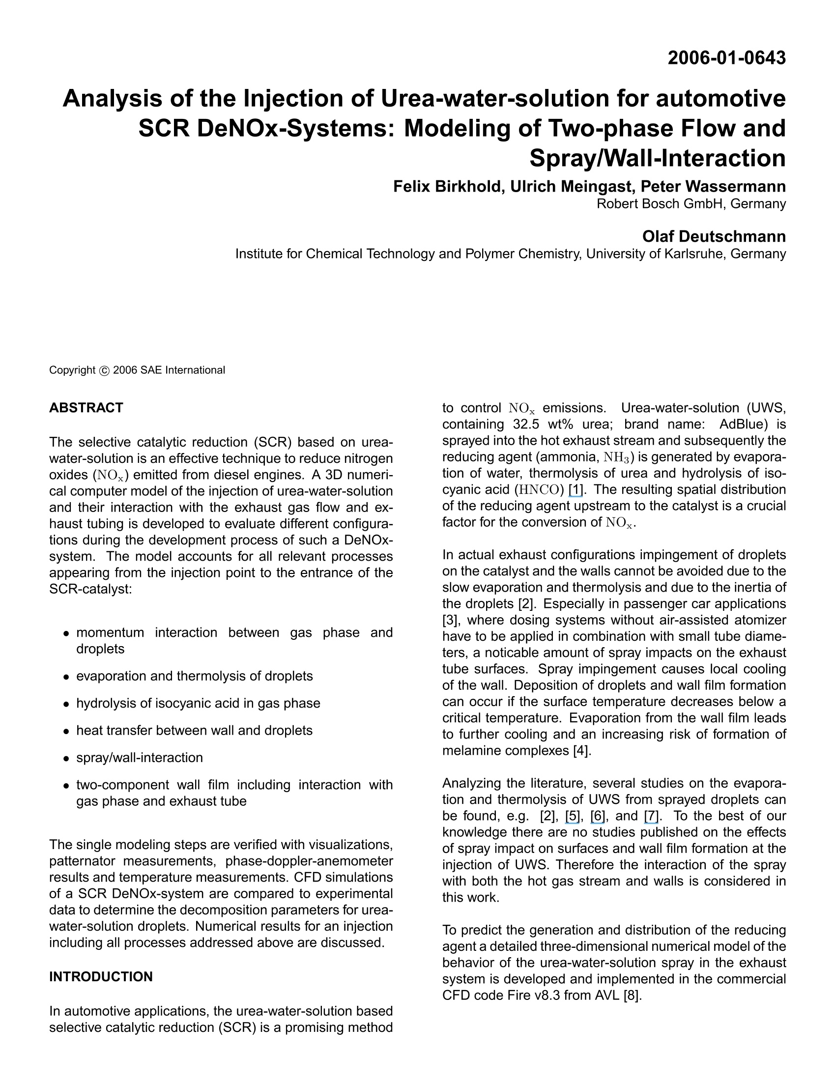
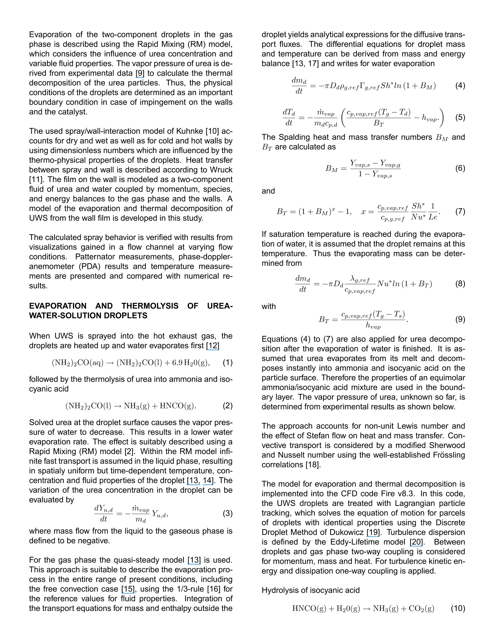
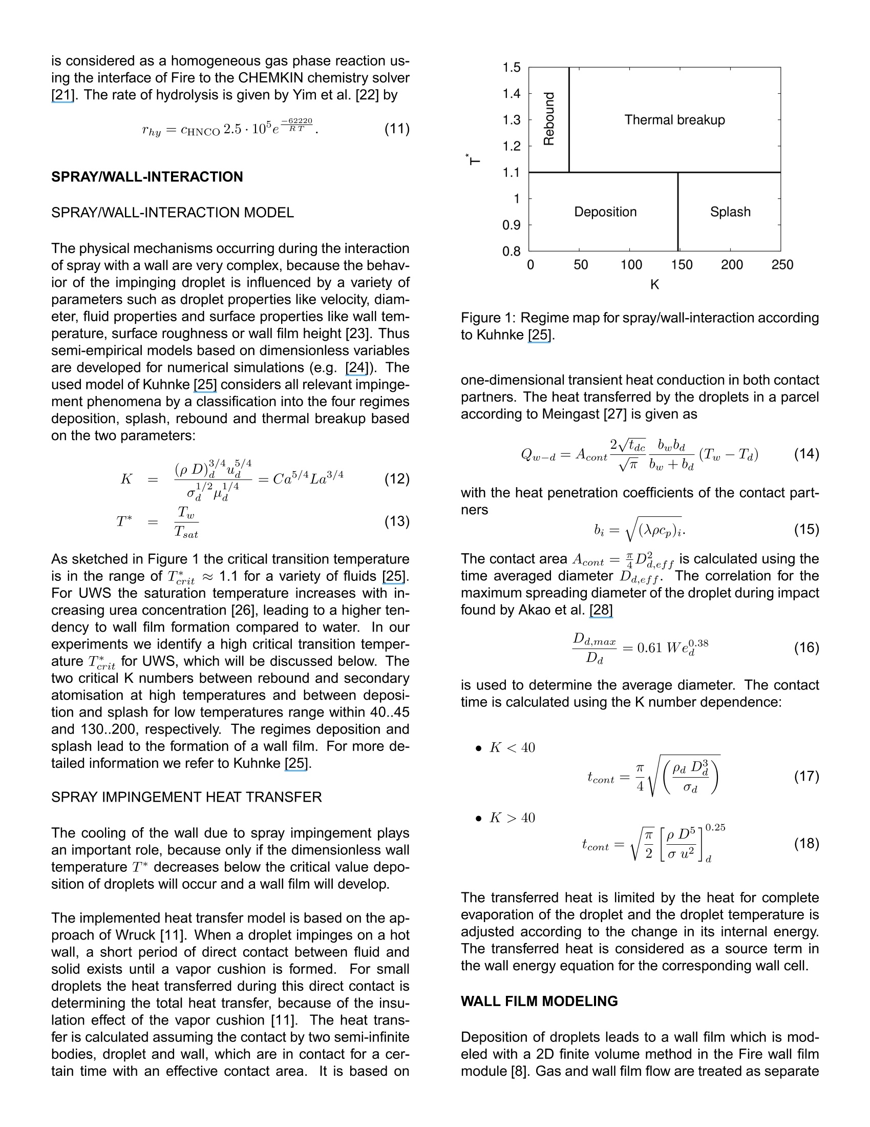
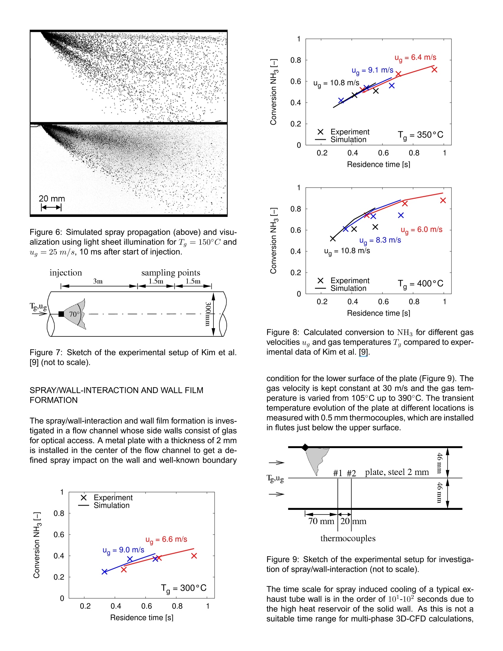
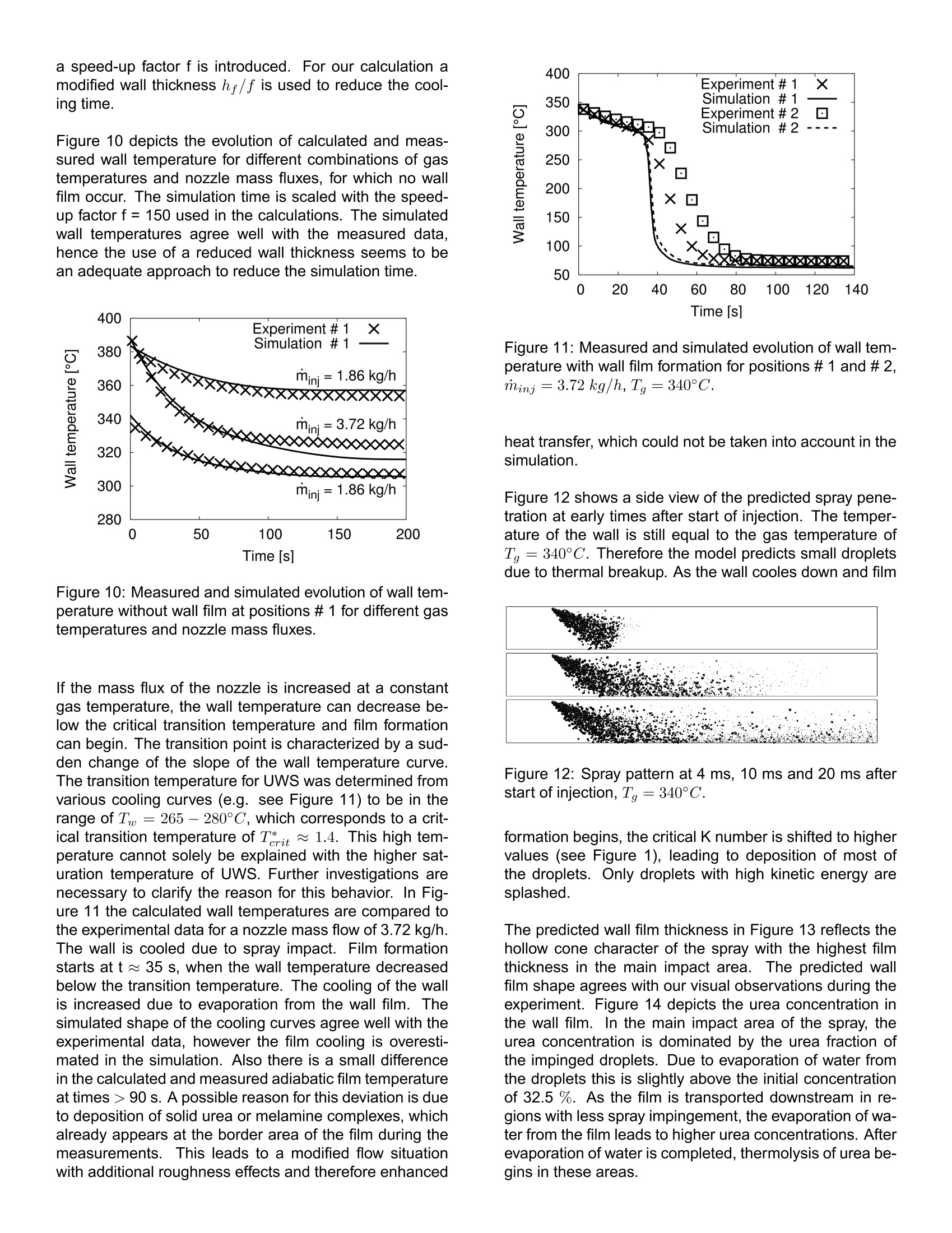
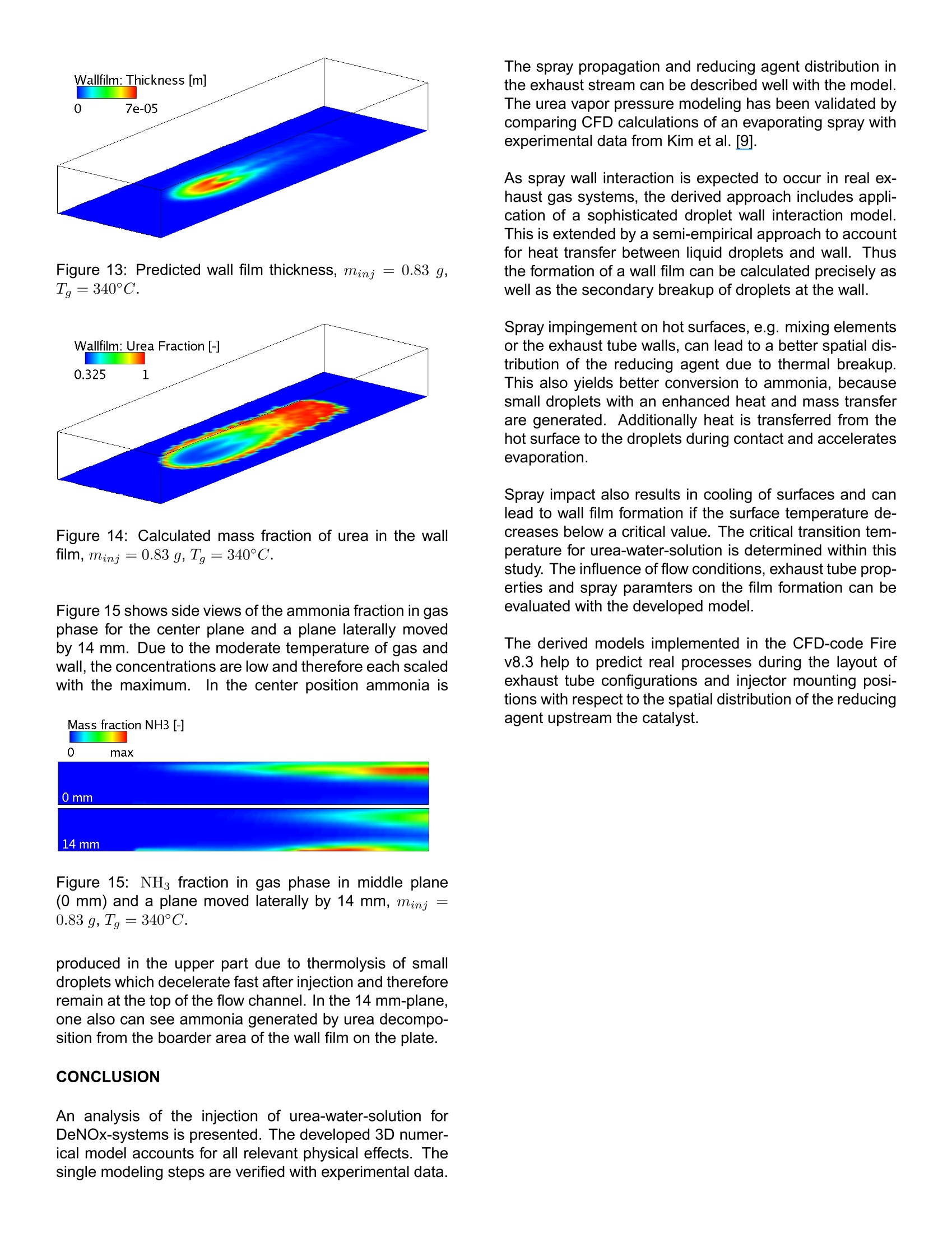
ResearchGateSee discussions,stats,and author profiles for this publication at: https://www.researchgate.net/publication/242294695 2006-01-0643View publication stats Analysis of the Injection of Urea-water-solutionfor automotive SCR DeNOx-Systems: Modelingof Two-phase Flow and... Article in SAE Technical Papers· January 2006 DOI: 10.4271/2006-01-0643 CITATIONS54 READS 540 4authors,including: Felix BirkholdRobert Bosch GmbH Olaf Deutschmann Karlsruhe Institute of Technology 4 PUBLICATIONS 173 CITATIONS 222 PUBLICATIONS 4,834CITATIONS SEE PROFILE SEE PROFILE All content following this page was uploaded by Olaf Deutschmann on 21 May 2014. ( The user has requested enhancement of the downloaded file. All in-t e xt references unde rlined in blue are a dde d to the original document and are linked to publications on ResearchGate, letting you access and read them immediately. ) Analysis of the Injection of Urea-water-solution for automotiveSCR DeNOx-Systems: Modeling of Two-phase Flow and Spray/Wall-Interaction Felix Birkhold, Ulrich Meingast, Peter WassermannRobert Bosch GmbH, Germany Olaf Deutschmann Institute for Chemical Technology and Polymer Chemistry, University of Karlsruhe, Germany ABSTRACT The selective catalytic reduction (SCR) based on urea-water-solution is an effective technique to reduce nitrogenoxides (NOx) emitted from diesel engines. A 3D numeri-cal computer model of the injection of urea-water-solutionand their interaction with the exhaust gas flow and ex-haust tubing is developed to evaluate different configura-tions during the development process of such a DeNOx-system. The model accounts for all relevant processesappearing from the injection point to the entrance of theSCR-catalyst: ●momentuminteractionbetweennigasphase aanddroplets · evaporation and thermolysis of droplets ·hydrolysis of isocyanic acid in gas phase ● heat transfer between wall and droplets · spray/wall-interaction two-component wall film including interaction withgas phase and exhaust tube The single modeling steps are verified with visualizations,patternator measurements, phase-doppler-anemometerresults and temperature measurements. CFD simulationsof a SCR DeNOx-system are compared to experimentaldata to determine the decomposition parameters for urea-water-solution droplets. Numerical results for an injectionincluding all processes addressed above are discussed. INTRODUCTION In automotiveapplications, the urea-water-solution basedselective catalytic reduction (SCR) is a promising method to control NOx emissions. Urea-water-solution (UWS,containing 32.5 wt% urea; brand name: AdBlue) issprayed into the hot exhaust stream and subsequently thereducing agent (ammonia, NH3) is generated by evapora-tion of water, thermolysis of urea and hydrolysis of iso-cyanic acid (HNCO) [1]. The resulting spatial distributionof the reducing agent upstream to the catalyst is a crucialfactor for the conversion of NO.. In actual exhaust configurations impingement of dropletson the catalyst and the walls cannot be avoided due to theslow evaporation and thermolysis and due to the inertia ofthe droplets [2]. Especially in passenger car applications[3], where dosing systems without air-assisted atomizerhave to be applied in combination with small tube diame-ters, a noticable amount of spray impacts on the exhausttube surfaces. Spray impingement causes local coolingof the wall. Deposition of droplets and wall film formationcan occur if the surface temperature decreases below acritical temperature. Evaporation from the wall film leadsto further cooling and an increasing risk of formation ofmelamine complexes [4]. Analyzing the literature, several studies on the evapora-tion and thermolysis of UWS from sprayed droplets canbe found, e.g.[2], [5],[6], and Z]. To the best of ourknowledge there are no studies published on the effectsof spray impact on surfaces and wall film formation at theinjection of UWS. Therefore the interaction of the spraywith both the hot gas stream and walls is considered inthis work. To predict the generation and distribution of the reducingagent a detailed three-dimensional numerical model of thebehavior of the urea-water-solution spray in the exhaustsystem is developed and implemented in the commercialCFD code Fire v8.3 from AVL [8]. Evaporation of the two-component droplets in the gasphase is described using the Rapid Mixing (RM) model,which considers the influence of urea concentration andvariable fluid properties. The vapor pressure ofurea is de-rived from experimental data [9] to calculate the thermaldecomposition of the urea particles. Thus, the physicalconditions of the droplets are determined as an importantboundary condition in case of impingement on the wallsand the catalyst. The used spray/wall-interaction model of Kuhnke [10] ac-counts for dry and wet as well as for cold and hot walls byusing dimensionless numbers which are influenced by thethermo-physical properties of the droplets. Heat transferbetween spray and wall is described according to Wruck[11]. The film on the wall is modeled as a two-componentfluid of urea and water coupled by momentum,species,and energy balances to the gas phase and the walls. Amodel of the evaporation and thermal decomposition ofUWS from the wall film is developed in this study. The calculated spray behavior is verified with results fromvisualizations gained in a flow channel at varying flowconditions. FPatternator measurements, phase-doppler-anemometer (PDA) results and temperature measure-ments are presented and compared with numerical re-sults. EVAPORATION AND THERMOLYSISOF UREA-WATER-SOLUTION DROPLETS When UWS is sprayed into the hot exhaust gas, thedroplets are heated up and water evaporates first [12] followed by the thermolysis of urea into ammonia and iso-cyanic acid Solved urea at the droplet surface causes the vapor pres-sure of water to decrease. This results in a lower waterevaporation rate. The effect is suitably described using aRapid Mixing(RM) model [2]. Within the RM model infi-nite fast transport is assumed in the liquid phase, resultingin spatialy uniform but time-dependent temperature, con-centration and fluid properties of the droplet [13, 14]. Thevariation of the urea concentration in the droplet can beevaluated by where mass flow from the liquid to the gaseous phase isdefined to be negative. For the gas phase the quasi-steady model [13] is used.This approach is suitable to describe the evaporation pro-cess in the entire range of present conditions, includingthe free convection case [15], using the 1/3-rule [16] forthe reference values for fluid properties. Integration ofthe transport equations for mass and enthalpy outside the droplet yields analytical expressions for the diffusive trans-port fluxes. The differential equations for droplet massand temperature can be derived from mass and energybalance [13, 17] and writes for water evaporation The Spalding heat and mass transfer numbers BM andBr are calculated as and If saturation temperature is reached during the evapora-tion of water, it is assumed that the droplet remains at thistemperature. Thus the evaporating mass can be deter-mined from with Equations (4) to (7) are also applied for urea decompo-sition after the evaporation of water is finished. It is as-sumed that urea evaporates from its melt and decom-poses instantly into ammonia and isocyanic acid on theparticle surface. Therefore the properties of an equimolarammonia/isocyanic acid mixture are used in the bound-ary layer. The vapor pressure of urea, unknown so far, isdetermined from experimental results as shown below. The approach accounts for non-unit Lewis number andthe effect of Stefan flow on heat and mass transfer. Con-vective transport is considered by a modified Sherwoodand Nusselt number using the well-established Frosslingcorrelations [18]. The model for evaporation and thermal decomposition isimplemented into the CFD code Fire v8.3. In this code,the UWS droplets are treated with Lagrangian particletracking, which solves the equation of motion for parcelsof droplets with identical properties using the DiscreteDroplet Method of Dukowicz [19]. Turbulence dispersionis defined by the Eddy-Lifetime model [20]. Betweendroplets and gas phase two-way coupling is consideredfor momentum, mass and heat. For turbulence kinetic en-ergy and dissipation one-way coupling is applied. Hydrolysis of isocyanic acid is considered as a homogeneous gas phase reaction us-ing the interface of Fire to the CHEMKIN chemistry solver[21]. The rate of hydrolysis is given by Yim et al. [22] by SPRAY/WALL-INTERACTION SPRAY/WALL-INTERACTION MODEL The physical mechanisms occurring during the interactionof spray with a wall are very complex, because the behav-ior of the impinging droplet is influenced by a variety ofparameters such as droplet properties like velocity, diam-eter, fluid properties and surface properties like wall tem-perature, surface roughness or wall film height [23]. Thussemi-empirical models based on dimensionless variablesare developed for numerical simulations (e.g. [24]). Theused model of Kuhnke [25] considers all relevant impinge-ment phenomena by a classification into the four regimesdeposition, splash, rebound and thermal breakup basedon the two parameters: As sketched in Figure 1 the critical transition temperatureis in the range of Terit ~ 1.1 for a variety of fluids [25].For UWS the saturation temperature increases with in-creasing urea concentration [26], leading to a higher ten-dency to wall film formation compared to water. In ourexperiments we identify a high critical transition temper-ature T* it for UWS, which will be discussed below. Thetwo critical K numbers between rebound and secondaryatomisation at high temperatures and between deposi-tion and splash for low temperatures range within 40..45and 130..200, respectively. The regimes deposition andsplash lead to the formation of a wall film. For more de-tailed information we refer to Kuhnke [25]. SPRAY IMPINGEMENT HEAT TRANSFER The cooling of the wall due to spray impingement playsan important role, because only if the dimensionless walltemperature T*decreases below the critical value depo-sition of droplets will occur and a wall film will develop. The implemented heat transfer model is based on the ap-proach of Wruck [11]. When a droplet impinges on a hotwall, a short period of direct contact between fluid andsolid exists until a vapor cushion is formed. For smalldroplets the heat transferred during this direct contact isdetermining the total heat transfer, because of the insu-lation effect of the vapor cushion [11]. The heat trans-fer is calculated assuming the contact by two semi-infinitebodies, droplet and wall, which are in contact for a cer-tain time with an effective contact area..It is based on Figure 1: Regime map for spray/wall-interaction accordingto Kuhnke[25]. one-dimensional transient heat conduction in both contactpartners. The heat transferred by the droplets in a parcelaccording to Meingast [27] is given as with the heat penetration coefficients of the contact part-ners The contact area Acont =一Da,eff is calculated using thei ave ed diameter Dieff. The correlatio r themaximum spreading diameter of the droplet during impactfound by Akao et al. [28] is used to determine the average diameter. The contacttime is calculated using the K number dependence: ·K<40 ●K>40 The transferred heat is limited by the heat for completeevaporation of the droplet and the droplet temperature isadjusted according to the change in its internal energy.The transferred heat is considered as a source term inthe wall energy equation for the corresponding wall cell. WALL FILM MODELING Deposition of droplets leads to a wall film which is mod-eled with a 2D finite volume method in the Fire wall filmmodule [8]. Gas and wall film flow are treated as separate single phases, coupled by semi-empirical boundary con-ditions. The film is transported due to shear forces, gravityand pressure gradients. CONTINUITY EQUATION The continuity equation transformed into conservation offilm thickness hy writes where u; and s, are the velocity components and the wall-parallel cartesian coordinates, respectively, and Sm is themass source, e.g. deposition of droplets. Assuming aspatially constant wall film thickness in a cell, equation(19) can be solved explicitly, if velocity components andthe source term are known. Sub-cycling is^rr1Fi applied to fulfillthe CFL condition uf▲t/Ax <1. Film velocity profiles aresolved analytically for laminar and turbulent flow, wherethe transition from laminar to turbulent film flow is charac-terized by a film Reynolds number and transition is assumed at Ref =2.7. Waviness of the film is modeled as a surface roughness,leading to modified logarithmic wall law for turbulent flows The value C+is constant for technically smooth surfacesbut varies according to Sattelmayer [29] with the rough-ness Reynolds number The equivalent sand grain roughness is determined with the correction function w proposed by Rosskamp[30]. Thus the logarithmic wall law is coupled with the wallshear equations, which can only be solved iteratively. Thisapproach works well for wall films of water or fuels [8],[31].Elsasser [32] identifies the relevant fluid properties for thedevelopment of a wall film as · the kinematic viscosity v and · the surface tension o. Our own measurements of the dynamic surface tensionof UWS show only a slight increase compared to watersurface tension (0.075 N/m vs. 0.072 N/m at 30°C), soits influence can be neglected in a first approximation, atleast for low urea concentrations. The viscosity increaseswith increasing urea concentration [26] and leads to anincrease of the film thickness and shear stress and a ten-dency to a laminar film profile [32].For high urea concen-trations the above approach may only be a rough estima-tion of the film dynamics. To account for the urea-water-solution a species transportequation for the urea fraction in the wall film is introduced where the right-hand side accounts for sources from de-posited droplets and urea thermolysis. Diffusive effectsare neglected in this study, because they contribute typi-cally less than 0.1 % to the mass flux between adjacentcells. Equation (24) is solved in the same way as the filmcontinuity equation (19) with an explicit Euler scheme withup-winding of flux terms. ENERGY EQUATION AND MASS TRANSFER The enthalpy balance equation of the wall film writes and is solved using a semi-implicit procedure for improvednumerical stability. The terms on the right hand side ac-count for heat transfer from the wall and the gas phase,cooling due to evaporation and thermolysis, and sourcesfrom impinged droplets. Evaporation and thermolysis from wall film is based onFick's law of diffusion where Y, is the interfacial vapor concentration and I thediffusion coefficient. For laminar or rather low Reynoldsnumber flows the discretised concentration gradient is ap-proximated with a second order interpolation. For mod-erate or high Reynolds number flows equation (26) un-derestimates the evaporation rates. For such conditionsthe evaporation model introduced by Sill [33], which as-sumes an analogy between momentum and mass trans-fer, is more accurate. The evaporation rate writes where ug is the gas velocity parallel to the wall. Stm isthe dimensionless Stanton number for mass transfer andcorrelates with the interfacial shear force. To account forStefan flow a correction according to Ackermann [34] isapplied. During the calculation the maximum of the twocomputed evaporation rates is taken. The saturation temperature of UWS can be reached dur-ing the evaporation of water due to the decrease of va-por pressure resulting from increasing urea concentration. Then the film enthalpy equation (25) is transformed to re-calculate the evaporating mass flux rap to get a wall filmtemperature just below the saturation point. Wall film en-ergy equation and the evaporation routines are coupledinthis study through a time step adaptation to avoid numeri-cal instabilities and to solve the steep gradients of heatingand evaporation of the wall film. WALL MODELLING Knowledge about the thermal behavior of the wall isimportant for an accurate calculation of the spray/wall-interaction and the wall film formation. Therefore the 2Dtransient energy equation for the wall enthalpy is introduced and solved semi-implicitly for every wall cell: with The index i denotes amb, f and g. The temperature dropin the wall is neglected, because the wall heat resis-tance is much lower than the resistance of convection(Aw/hw << Qamb-w and of-w). The maximal temper-ature difference between inner and outer surface of thewall is typically less than 2°C in exhaust systems. Either Qf-w or Qg-w are used in equation (29), depend-ing of whether there exists a wall film in the adjacentfluid cell. The heat transfer coefficients between film andwall, af-w, are calculated assuming conduction with lin-ear temperature profiles in film and wall If the wall temperature is above the saturation temperatureof UWS, vapor bubbles are generated at the liquid-solidinterface influencing the surface heat flux. The heat fluxdepending on the excess temperature ATe= Tw - Tsatis calculated following the Nukiyama boiling curve accord-ing to Incropera and De Witt [35]. In the free convectionboiling region (0°℃ 90 s. A possible reason for this deviation is dueto deposition of solid urea or melamine complexes, whichalready appears at the border area of the film during themeasurements.This leads to a modified flow situationwith additional roughness effects and therefore enhanced Figure 11: Measured and simulated evolution of wall tem-perature with wall film formation for positions #1 and #2,Tinj=3.72 kg/h,Tg=340°C. heat transfer, which could not be taken into account in the1simulation. Figure 12 shows a side view of the predicted spray pene-tration at early times after start of injection. The temper-ature of the wall is still equal to the gas temperature ofTg =340°C. Therefore the model predicts small dropletsdue to thermal breakup. As the wall cooles down and film Figure 12: Spray pattern at 4 ms, 10 ms and 20 ms afterstart of injection, Tg=340°C. formation begins, the critical K number is shifted to highervalues (see Figure 1), leading to deposition of most ofthe droplets. Only droplets with high kinetic energy aresplashed. The predicted wall film thickness in Figure 13 reflects thehollow cone character of the spray with the highest filmthickness in the main impact area.The predicted wallfilm shape agrees with our visual observations during theexperiment. Figure 14 depicts the urea concentration inthe wall film. In the main impact area of the spray, theurea concentration is dominated by the urea fraction ofthe impinged droplets. Due to evaporation of water fromthe droplets this is slightly above the initial concentrationof 32.5 %. As the film is transported downstream in re-gions with less spray impingement,the evaporation of wa-ter from the film leads to higher urea concentrations. Afterevaporation of water is completed, thermolysis of urea be-gins in these areas. Figure 13: Predicted wall film thickness, Minj;=0.83 g,T=340°C. Figure 14: Calculated mass fraction of urea in the wallfilm, minj=0.83 g, Tg=340°C. Figure 15 shows side views of the ammonia fraction in gasphase for the center plane and a plane laterally movedby 14 mm. Due to the moderate temperature of gas andwall, the concentrations are low and therefore each scaledwith the maximum.In the center position ammonia is Mass fraction NH3- Figure 15: NH fraction in gas phase in middle plane(0 mm) and a plane moved laterally by 14 mm, minj =0.83 g,Tg=340°C. produced in the upper part due to thermolysis of smalldroplets which decelerate fast after injection and thereforeremain at the top of the flow channel. In the 14 mm-plane,one also can see ammonia generated by urea decompo-sition from the boarder area of the wall film on the plate. CONCLUSION An analysis of the injection of urea-water-solution forDeNOx-systems is presented. The developed 3D numer-ical model accounts for all relevant physical effects. Thesingle modeling steps are verified with experimental data. The spray propagation and reducing agent distribution inthe exhaust stream can be described well with the model.The urea vapor pressure modeling has been validated bycomparing CFD calculations of an evaporating spray withexperimental data from Kim et al.[9]. As spray wall interaction is expected to occur in real ex-haust gas systems, the derived approach includes appli-cation of a sophisticated droplet wall interaction model.This is extended by a semi-empirical approach to accountfor heat transfer between liquid droplets and wall. Thusthe formation of a wall film can be calculated precisely aswell as the secondary breakup of droplets at the wall. Spray impingement on hot surfaces, e.g. mixing elementsor the exhaust tube walls, can lead to a better spatial dis-tribution of the reducing agent due to thermal breakup.This also yields better conversion to ammonia, becausesmall droplets with an enhanced heat and mass transferare generated. Additionally heat is transferred from thehot surface to the droplets during contact and acceleratesevaporation. Spray impact also results in cooling of surfaces and canlead to wall film formation if the surface temperature de-creases below a critical value. The critical transition tem-perature for urea-water-solution is determined within thisstudy. The influence of flow conditions, exhaust tube prop-erties and spray paramters on the film formation can beevaluated with the developed model. The derived models implemented in the CFD-code Firev8.3 help to predict real processes during the layout ofexhaust tube configurations and injector mounting posi-tions with respect to the spatial distribution of the reducingagent upstream the catalyst. Modeling, 1D Kinetic Analysis and 3D System Simu- [7] M. Chen and S. Williams. Modelling and Optimiza-tion of SCR-Exhaust Aftertreatment Systems. SAE,2005-01-0969,2005. ( [8] FIRE 8.3. AVL LIST GmbH, A-8020 G r az, Austria, www.avl.com,2004. ) ( [9] J.Y. Kim, S.H. Ryu, and J.S. Ha. N umerical predic- tion on t he c haracteristics o f s pray-induced m i xing and the rm al decomposition of urea solution i n SCR system. I n P roc. 2 004 Fall T echnical Conferenceof the ASME Internal Combustion Engine Division,Long Beach, C alifornia USA,2004. ) ( [10] D. Kuhnke. S p ray/Wall-Interaction Modelling by D i -mensionless Data Analysis. Shaker Verlag, 2004. ISBN 3-8322-3539-6. ) ( [11] N. W. Wruck. Transientes Sieden von Tropfen beimWandaufprall. PhD thesis, RWTH Aachen, 1 998. ) ( [12 ] M. K oebel, M. E lsener, and M. K leemann. Urea- SCR: a p romising t echnique to reduce NOx emis- sions fr om automoti v e diesel engines. Catalysis To- iday.,59:335-345,2000. ) ( [13 ] G.M. F aeth. Evaporation and combustion of sprays. Pro g . E ner gy Co mb ust . Sc i ., 9:1- 76 , 1 9 83. ) ( [14] W . A. S irignano. F uel droplet vaporization and spray co mbus t ion t he o ry . P r og . E n erg y Combu s t. Sci., 9: 291-322,1983. ) ( [15 ] M. B urger, R. Schmehl, I P. Prommersberger, O. S chaef er, R. Koch, and S. Wittig. Droplet evap- oration modeling b y the distillation curve m odel: a c - counting for kerosine fuel and elevated pressures. Int. J. Heat Mass Transfer,46:4403-4412,2003. ) ( [16] E.M. Sparrow and J .L. Gregg. Th e variable fluid- property problem in free convection. Trans. ASME80,1958. ) ( [17] B. A bramzon and W.A. Sirig n a no. D roplet vaporiza- tion model for spray combustion c a lculations. Int. J.Heat Mass Transfer, 32:1605-1618 , 1989. ) ( [18] N. F rossling. Uber d ie V erdunstung i fallender Tropfen. Gerlands B eitrag zur Geophysik, 52:170-216,1938. ) ( [19] J.K . Dukowicz . A particle-fluid numerical model f or liqu i d sprays. Journal of Computat io nal P hysics, 35: 229-253,1980. ) ( [20] A .D. Gos m a n a nd E. lo anni des.Aspects of c ompu ter simulation of liquid-fueled combusters. In AIAA-81- 323.AIAA1981. ) ( [21 ] R.J. Kee, F.M. Ruple y, E. Meeks, a nd J.A. M iller. Chemkin II: A fortran chemical k inetics package forthe analysis of gas-phase chemical a nd plasma ki-netics. Sandia National Laboratories, Livermore, CA 94551-0969,1996. ) ( [22] D.S. Yim, S.J. Kim, J.H. Baik, I . Nam, Y.S. Mok, J.W.Lee, B.K. Cho , and S.H. Oh. Decomposition of Ureainto NH3 for the SCR Process. I nd.Eng.Chem.Res.,43(1):4856-4863,2004. ) ( [23] Chr. Mundo, M. Sommerfeld, and C. Tropea. Droplet-wall collisions: Experimental studies of the deforma-tion and breakup process. I n t. J. of Multiphase Flow,21(2):151-173,1995. ) ( [24] C. Bai and A.D. Gosman. Development of methodol- ogy for spray impingement simulation. SAE, 950283, 1995. ) ( [25] D. Kuhnke. Spray/Wall-Interaction Modelling by Di- mensionless Data Analysis. P h D thesis, Universitat Darmstadt, 2004. ) ( [26] L. Jaeger, J. Nyvlt, S. Horacek, and J. G o ttfried.Viskositaten von Harnstoffwasserlosungen.Collec- tion Czech. Chem.Commun.,30:2117-2121,1965. ) ( [27] U. Meingast. Spray/Wand-Wechselwirkung bei derdieselmotorischen D irekteinspritzung. P h D th e sis,RWTH Aachen,2003. ) ( [28] J. Akao, K. Araki, S . Mori, and A. Moriyama. Defor- mation b ehaviors o f a l i quid d rople t i mpinging o n t o hot metal surface. T rans. lron and Steel Institue of Jap an, 20:73 7 -743, 198 0. ) ( [29] T. Sattelmayer. Zum Einflus s der a u sgeb i l deten turbulenten Luft-Flussigkeitsfilm-Stromu n gauf den Filmzerfal l und die Tropfenbildung am Austritt v onSpalten geringer Hohe. PhD thesis, Universitat Karl- sruhe (TH), 1985. ) ( [30] H . Rosskamp. Simulation v on d r allbehafteten Zweiphasenstrmungen mit schubspannugsgetriebe- nen Wandfilmen. Ph D thesis, Universitat Karlsruhe (TH), 1998. ) ( [31] J . Himmelsbach . Zweiphasenstromung mit schub-spannungsgetriebenen, we l ligen Fl u ssigkeitsfilmenin turbulenter Heissgasstromung-MesstechnischeErfassung und numerische Beschreibung. P hD the-sis, Universitat Karlsruhe (TH), 1992. ) ( [32] A. Elsasser. Kraftstoffaufbereitun g i n Verbren-nungskraftmaschinen: G rundlagen d er Stromungschubspannungsgetriebener Wandfilmen. PhD the-sis, Universita t Karlsruhe (TH), 1998. ) ( [33] K. H. Sill. Warme- u n d Stoffubertragung in tu r bu-lenten Stromungsgrenzschichten langs verdunsten-der welliger Flussigkeitsfilme. PhD thesis, UniversitatKarlsruhe (TH), 1982. ) ( [34] G. Ackermann. Warmeubergang u nd m oleku- lare Stoffubertragung im g leic h e n Fel d bei gro sse n Temperatur- u nd Partialdruckdifferenzen. VDI- Forschungshefte, ( Nr.382):1-16, 1937. ) ( [35] F. P. Incropera and D. P. De Witt. Fundamentals o f Heat and Mass Transfer. Wiley and S ons, 5 th edition, 2002. ISBN 0-471-38650-2. ) ( [36]VDI-Warmeatlas. VDI-Gesellschaft, eighth edition,Springer, 1997. ) ( [37] Davis 6 .2.4. LaVision GmbH, D -37081 Gottingen,Germany, www.lavision.de, 2 002. ) The selective catalytic reduction (SCR) based on ureawater-solution is an effective technique to reduce nitrogenoxides (NOx) emitted from diesel engines. A 3D numericalcomputer model of the injection of urea-water-solutionand their interaction with the exhaust gas flow and exhausttubing is developed to evaluate different configurationsduring the development process of such a DeNOxsystem.The model accounts for all relevant processesappearing from the injection point to the entrance of theSCR-catalyst:• momentum interaction between gas phase anddroplets• evaporation and thermolysis of droplets• hydrolysis of isocyanic acid in gas phase• heat transfer between wall and droplets• spray/wall-interaction• two-component wall film including interaction withgas phase and exhaust tubeThe single modeling steps are verified with visualizations,patternator measurements, phase-doppler-anemometerresults and temperature measurements. CFD simulationsof a SCR DeNOx-system are compared to experimentaldata to determine the decomposition parameters for ureawater-solution droplets. Numerical results for an injectionincluding all processes addressed above are discussed.
确定
还剩10页未读,是否继续阅读?

产品配置单


北京欧兰科技发展有限公司为您提供《尿素-水溶液喷射中两相流动和喷雾/壁面相互作用建模检测方案(尾气检测)》,该方案主要用于其他中其他检测,参考标准--,《尿素-水溶液喷射中两相流动和喷雾/壁面相互作用建模检测方案(尾气检测)》用到的仪器有汽车发动机多参量测试系统、Imager sCMOS PIV相机、德国LaVision PIV/PLIF粒子成像测速场仪、PLIF平面激光诱导荧光火焰燃烧检测系统、LaVision SprayMaster 喷雾成像测量系统


相关方案
更多
该厂商其他方案
更多