


方案详情
文
Air-aqueous sodium halide solution interfaces are examined using vibrational sum frequency generation(SFG)
spectroscopy. Raman and ATR-FTIR (attenuated total reflection Fourier transform infrared) spectroscopies
are also used to compare the effects of halide anions on the water structure of the bulk solution to that of the
interface. The interfacial water structures for the sodium fluoride and chloride aqueous solutions are found to
be similar to the air-water interface, whereas sodium bromide and iodide aqueous solutions cause significant
distortion of the hydrogen-bonding network. Analysis of the spectra indicates higher concentrations of bromide
and iodide anions in the interfacial region with an increase in interfacial depth.
方案详情

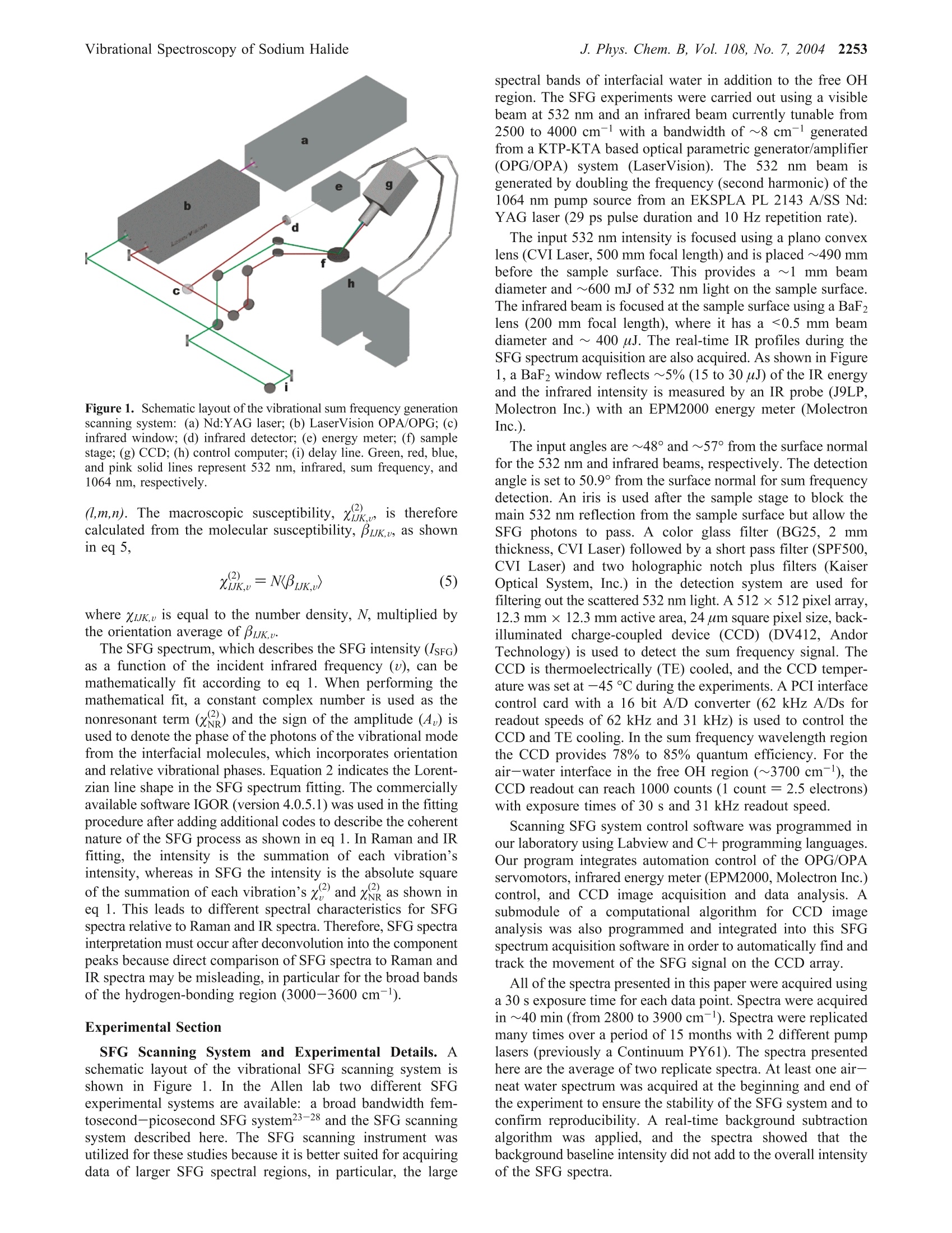
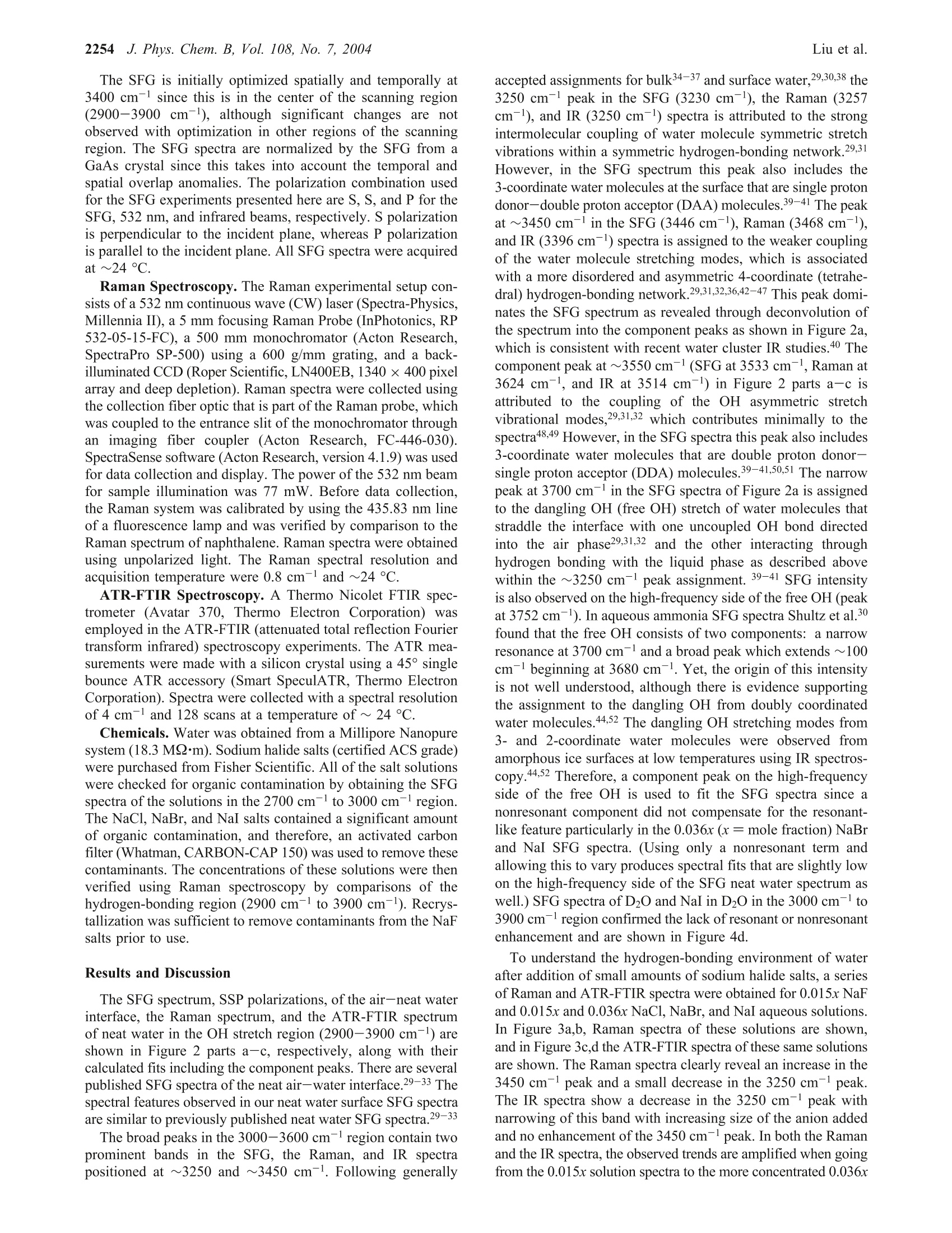
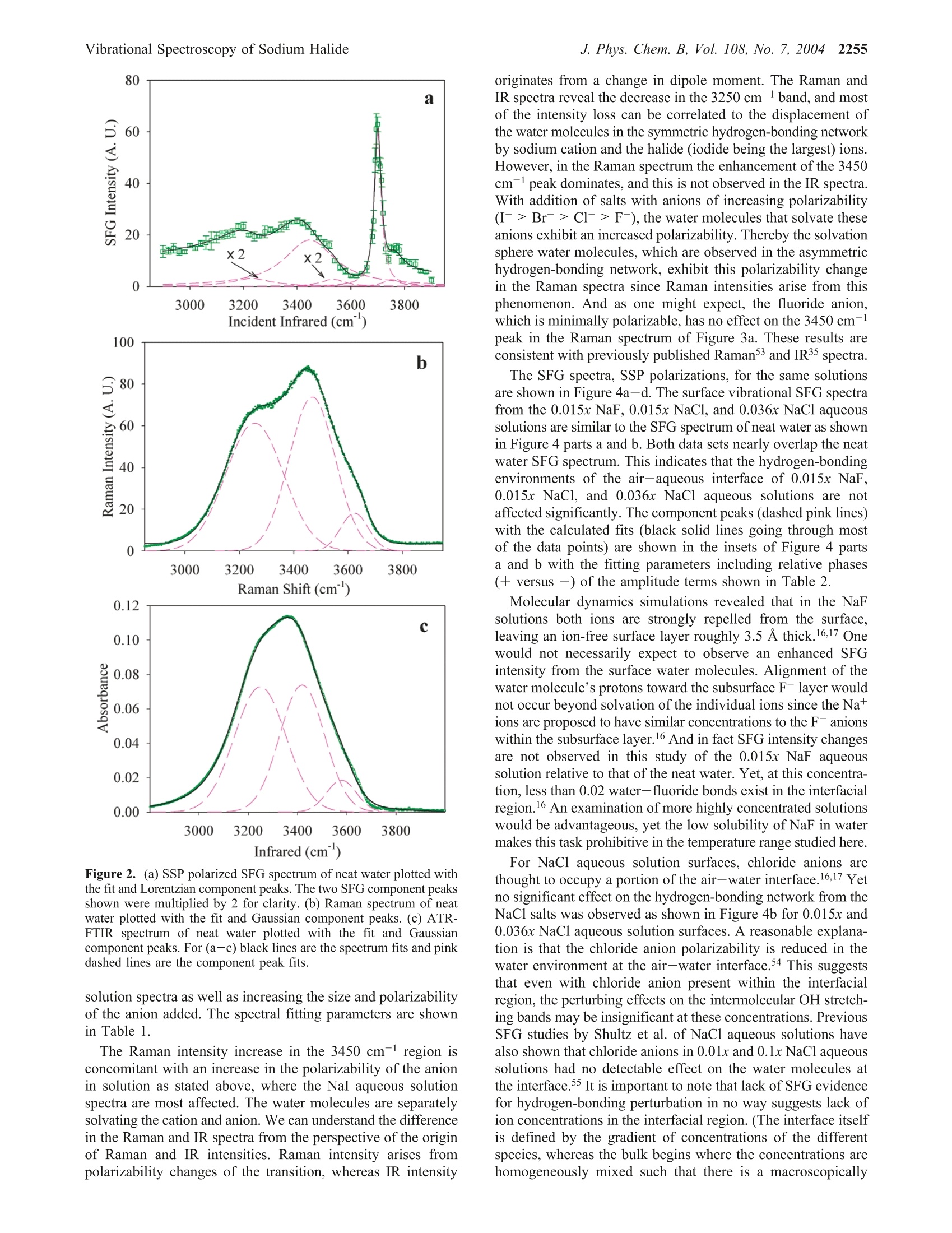
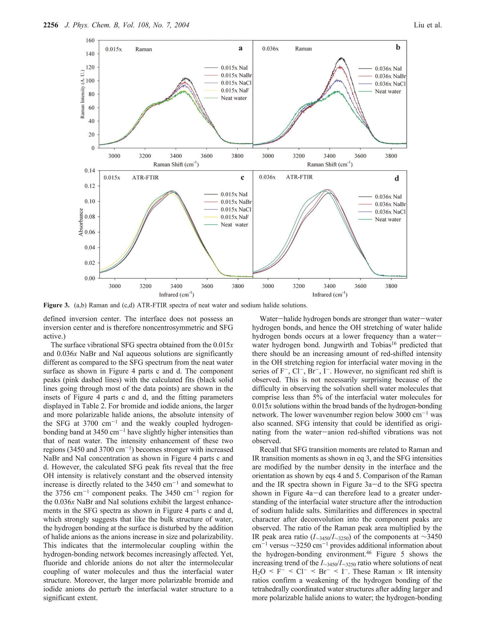
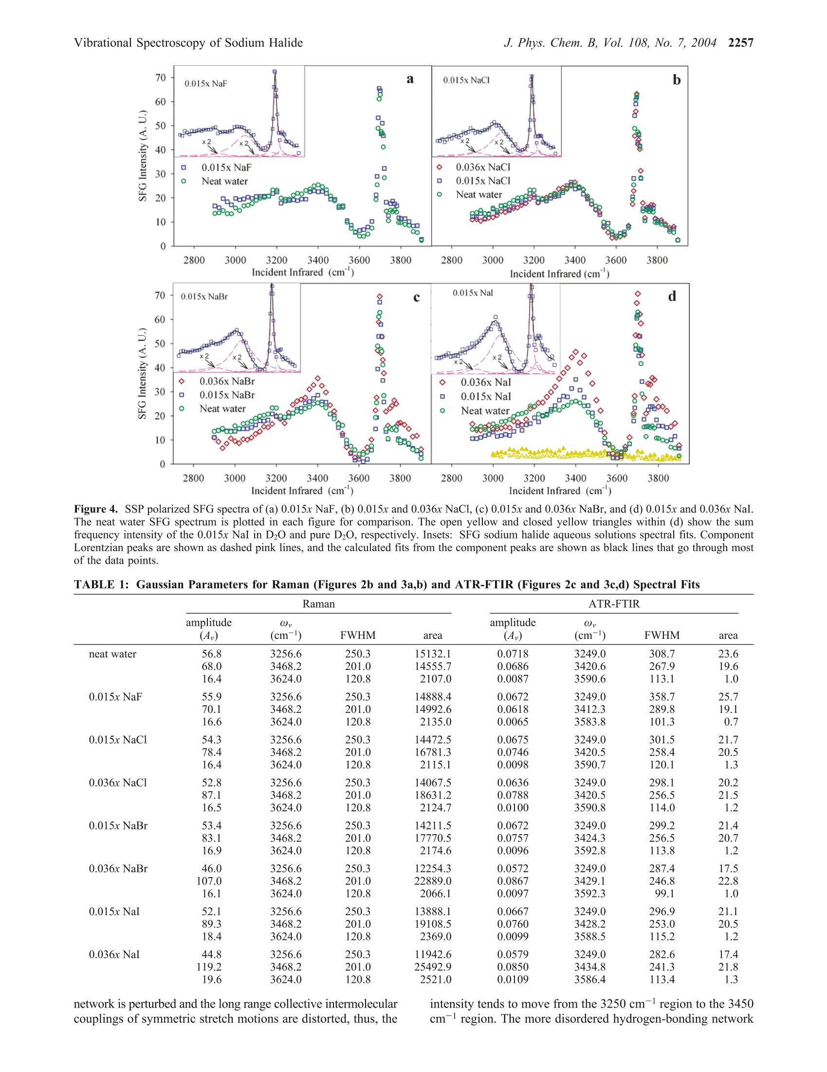
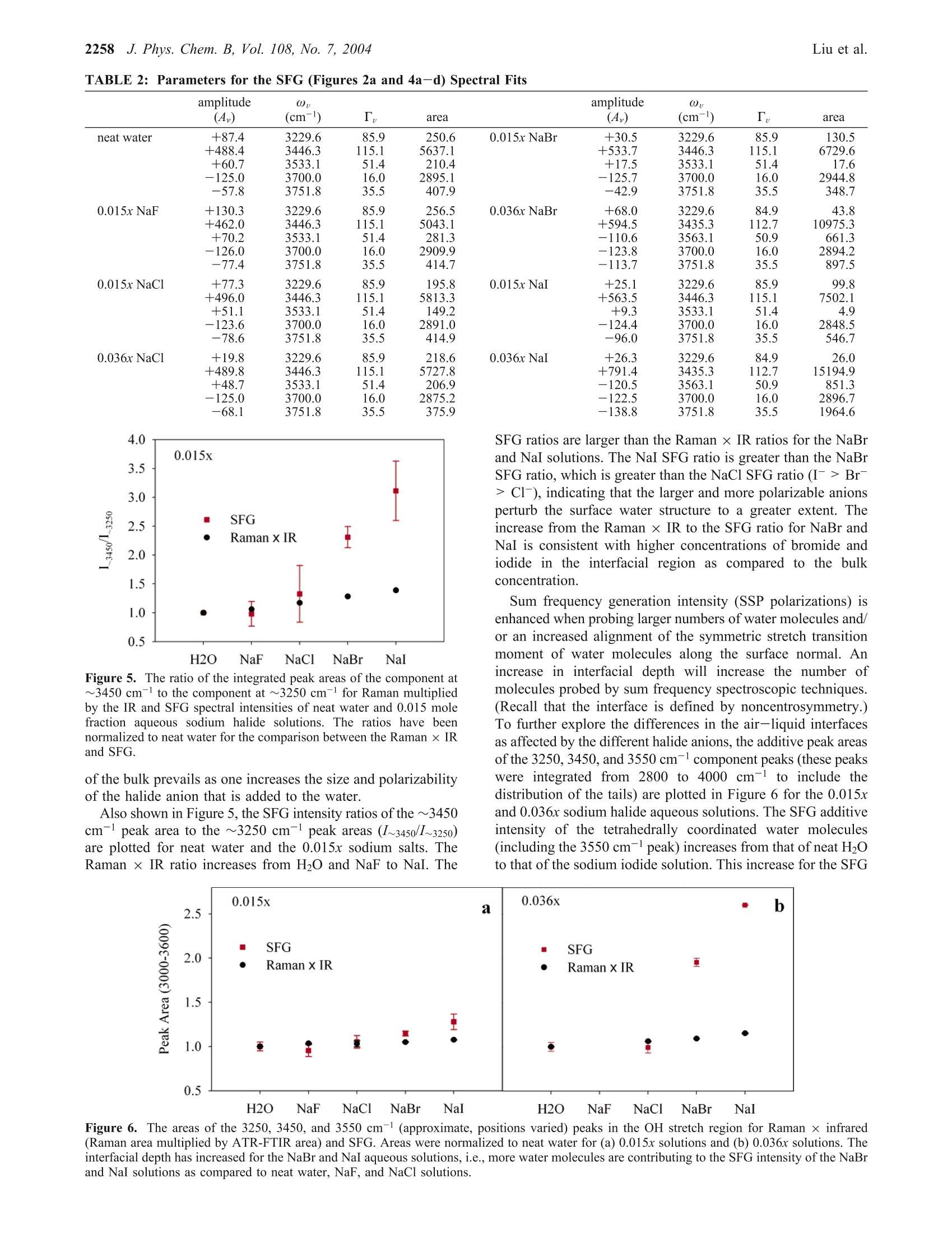
J. Phys. Chem. B 2004,108,2252-22602252 J. Phys. Chem. B, Vol. 108, No. 7, 2004Vibrational Spectroscopy of Sodium Halide2253 10.1021/jp036169r CCC: $27.50 C 2004 American Chemical SocietyPublished on Web 01/24/2004 Vibrational Spectroscopy of Aqueous Sodium Halide Solutions and Air-Liquid Interfaces:Observation of Increased Interfacial Depth Dingfang Liu, Gang Ma, Lori M. Levering, and Heather C. Allen* Department of Chemistry, The Ohio State University, 100 West 18th Avenue, Columbus, Ohio 43210Received: March 27, 2003; In Final Form: December 9, 2003 Air-aqueous sodium halide solution interfaces are examined using vibrational sum frequency generationspectroscopy. Raman and ATR-FTIR (attenuated total reflection Fourier transform infrared) spectroscopiesare also used to compare the effects of halide anions on the water structure of the bulk solution to that of theinterface. The interfacial water structures for the sodium fluoride and chloride aqueous solutions are found tobe similar to the air-water interface, whereas sodium bromide and iodide aqueous solutions cause significantdistortion of the hydrogen-bonding network. Analysis of the spectra indicates higher concentrations of bromideand iodide anions in the interfacial region with an increase in interfacial depth. Introduction The frequent and sudden decrease of ozone concentration inthe lower troposphere of the Arctic at polar sunrise has beenobserved for over a decade.1-3 Catalytic reactions involvingreactive halogen atoms are considered to be the major contribut-ing factor to the Arctic tropospheric ozone depletion.4-6 Theoxidation of halide anions in sea salt aerosol, snow, and thefrozen ocean surface7-10 has been shown to yield active halogencompounds such as BrO.11,12 These oxidation processes occurnot only in the bulk liquid but also at air-liquid interfaces, andthe latter may play a crucial role in the uptake and reaction ofgases with droplets in the troposphere.'Reactions between gases(e.g., O3) and halide anions are enhanced at the interfacecompared to the bulk solution.13 Aerosol chamber experiments,molecular dynamics (MD), and kinetic modeling studies foundthat measurements of the gaseous molecular chlorine productsare explainable only if reactions at the air-water interface aredominant. Although the existence of halide ions in the interfacial regionhas been postulated from recent studies,5,l3 direct experimentalmeasurement of this phenomenon has remained elusive due tothe difficulties inherent in measuring the structure and composi-tion of air-liquid interfaces. In terms of the Gibbs adsorptionequation, interpretation of the traditional theory suggests thatthere are no atomic ions at the air-solution interface.14-16 Onthe contrary, recent molecular dynamics simulations by Jung-wirth and Tobias16,17 reveal that although the small, nonpolar-izable fluoride anion is excluded from the air-water interface.the larger more polarizable halide anions are present in theinterfacial region. Bromide and iodide anions are shown to havehigher concentrations in the interfacial region than in thebulk.16,17 This theoretical picture of ions at the air-liquidinterface can be tested by interface-selective spectroscopictechniques. In this study, vibrational sum frequency generation(SFG) spectroscopy, an interface-selective spectroscopy, is usedto investigate the interfacial water structure of several aqueoussodium halide air-solution interfaces. The theory of SFG has been described previously.18-22However, a brief overview of SFG theory is presented here since ( * Auth i o o r r to whom c o rrespondence s h ould b e addressed. E -m ail:allen@chemistry.ohio-state.edu. ) it is the focus of this work. SFG is a second-order nonlinearprocess that occurs in noncentrosymmetric environments suchas interfaces under the electric dipole approximation. The SFGintensity, IsFG, as shown in eq 1, is proportional to the absolute square of the macroscopic second-order nonlinear susceptibility, x, which consists of resonantterms (x) and a nonresonant term (x). When the frequencyof an incident infrared beam, wI, is resonant with a vibrationalmode of an interfacial molecule, u, the resonant susceptibilityterm , dominates x(2) and a SFG intensity enhancement isobserved.x is shown in eq 2, where A, is the amplitude of the transition moment, v is thefrequency of the transition moment,and T, describes the line-width of the transition. The amplitude, Au, is nonzero when theRaman and the infrared transitions are spectroscopically allowed.The macroscopic nonlinear susceptibility x(2 is related to themolecular susceptibility, Bimm, The molecular susceptibility canbe described by eq 3, where represents the Raman transition moment, represents the IR transition moment for the molecule,and Imn represents the molecular coordination system. An Eulerangle transformation relates the molecular coordinate system(l,m,n) to the laboratory coordinate system (I,J,K). The trans-formation is shown in eq 4 where piJk:mn is the Euler angle transformation between thelaboratory coordinates (L,J,K) and the molecule coordinates Figure 1. Schematic layout of the vibrational sum frequency generationscanning system: (a) Nd:YAG laser; (b) LaserVision OPA/OPG; (c)infrared window; (d) infrared detector; (e) energy meter; (f) samplestage; (g) CCD; (h) control computer; (i) delay line. Green,red, blue,and pink solid lines represent 532 nm, infrared, sum frequency, and1064 nm, respectively. (l,m,n). The macroscopic susceptibility, xuk., is thereforecalculated from the molecular susceptibility, BuK,u, as shownin eq 5, where Xuk,u is equal to the number density, N, multiplied bythe orientation average of BuK,u The SFG spectrum, which describes the SFG intensity (IsrG)as a function of the incident infrared frequency (u), can bemathematically fit according to eq 1. When performing themathematical fit, a constant complex number is used as thenonresonant term (x) and the sign of the amplitude (A ) isused to denote the phase of the photons of the vibrational modefrom the interfacial molecules, which incorporates orientationand relative vibrational phases. Equation 2 indicates the Lorent-zian line shape in the SFG spectrum fitting. The commerciallyavailable software IGOR (version 4.0.5.1) was used in the fittingprocedure after adding additional codes to describe the coherentnature of the SFG process as shown in eq 1. In Raman and IRfitting, the intensity is the summation of each vibration’sintensity, whereas in SFG the intensity is the absolute squareof the summation of each vibration’sx, and xie as shown ineq 1. This leads to different spectral characteristics for SFGspectra relative to Raman and IR spectra. Therefore, SFG spectrainterpretation must occur after deconvolution into the componentpeaks because direct comparison of SFG spectra to Raman andIR spectra may be misleading, in particular for the broad bandsof the hydrogen-bonding region (3000-3600 cm-). Experimental Section SFG Scanning System and Experimental Details. Aschematic layout of the vibrational SFG scanning system isshown in Figure 1. In the Allen lab two different SFGexperimental systems are available: a broad bandwidth fem-tosecond-picosecond SFG system23-28 and the SFG scanningsystem described here. The SFG scanning instrument wasutilized for these studies because it is better suited for acquiringdata of larger SFG spectral regions, in particular, the large spectral bands of interfacial water in addition to the free OHregion. The SFG experiments were carried out using a visiblebeam at 532 nm and an infrared beam currently tunable from2500 to 4000 cm- with a bandwidth of~8 cm- generatedfrom a KTP-KTA based optical parametric generator/amplifier(OPG/OPA) system (LaserVision). The 532 nm beam isgenerated by doubling the frequency (second harmonic) of the1064 nm pump source from an EKSPLA PL 2143 A/SS Nd:YAG laser (29 ps pulse duration and 10 Hz repetition rate). The input 532 nm intensity is focused using a plano convexlens (CVI Laser, 500 mm focal length) and is placed ~490 mmbefore the sample surface. This provides a~1 mm beamdiameter and ~600 mJ of 532 nm light on the sample surface.The infrared beam is focused at the sample surface using a BaF2lens (200 mm focal length), where it has a <0.5 mm beamdiameter and ~400 pJ. The real-time IR profiles during theSFG spectrum acquisition are also acquired. As shown in Figure1, a BaF2 window reflects ~5% (15 to 30 uJ) of the IR energyand the infrared intensity is measured by an IR probe (J9LP,Molectron Inc.) with an EPM2000 energy meter (MolectronInc.). The input angles are ~48°and~57° from the surface normalfor the 532 nm and infrared beams, respectively. The detectionangle is set to 50.9° from the surface normal for sum frequencydetection. An iris is used after the sample stage to block themain 532 nm reflection from the sample surface but allow theSFG photons to pass. A color glass filter (BG25, 2 mmthickness, CVI Laser) followed by a short pass filter (SPF500,CVI Laser) and two holographic notch plus filters (KaiserOptical System, Inc.) in the detection system are used forfiltering out the scattered 532 nm light. A 512 × 512 pixel array,12.3 mmx12.3 mm active area, 24 um square pixel size,back-illuminated charge-coupled device (CCD) (DV412, AndorTechnology) is used to detect the sum frequency signal. TheCCD is thermoelectrically (TE) cooled, and the CCD temper-ature was set at -45 C during the experiments. A PCI interfacecontrol card with a 16 bit A/D converter (62 kHz A/Ds forreadout speeds of 62 kHz and 31 kHz) is used to control theCCD and TE cooling. In the sum frequency wavelength regionthe CCD provides 78% to 85% quantum efficiency. For theair-water interface in the free OH region (~3700cm-), theCCD readout can reach 1000 counts (1 count =2.5 electrons)with exposure times of 30 s and 31 kHz readout speed. Scanning SFG system control software was programmed inour laboratory using Labview and C+programming languages.Our program integrates automation control of the OPG/OPAservomotors, infrared energy meter (EPM2000, Molectron Inc.)control, and CCD image acquisition and data analysis. Asubmodule of a computational algorithm for CCD imageanalysis was also programmed and integrated into this SFGspectrum acquisition software in order to automatically find andtrack the movement of the SFG signal on the CCD array. All of the spectra presented in this paper were acquired usinga 30 s exposure time for each data point. Spectra were acquiredin ~40 min (from 2800 to 3900 cm-). Spectra were replicatedmany times over a period of 15 months with 2 different pumplasers (previously a Continuum PY61). The spectra presentedhere are the average of two replicate spectra. At least one air-neat water spectrum was acquired at the beginning and end ofthe experiment to ensure the stability of the SFG system and toconfirm reproducibility. A real-time background subtractionalgorithm was applied, and the spectra showed that thebackground baseline intensity did not add to the overall intensityof the SFG spectra. The SFG is initially optimized spatially and temporally at3400 cm- since this is in the center of the scanning region(2900-3900 cm-), although significant changes are notobserved with optimization in other regions of the scanningregion. The SFG spectra are normalized by the SFG from aGaAs crystal since this takes into account the temporal andspatial overlap anomalies. The polarization combination usedfor the SFG experiments presented here are S, S, and P for theSFG, 532 nm, and infrared beams, respectively.S polarizationis perpendicular to the incident plane, whereas P polarizationis parallel to the incident plane. All SFG spectra were acquiredat ~24°C. Raman Spectroscopy. The Raman experimental setup con-sists of a 532 nm continuous wave (CW) laser (Spectra-Physics,Millennia II), a 5 mm focusing Raman Probe (InPhotonics, RP532-05-15-FC), a 500 mm monochromator (Acton Research,SpectraPro SP-500) using a 600 g/mm grating, and a back-illuminated CCD (Roper Scientific,LN400EB, 1340×400 pixelarray and deep depletion). Raman spectra were collected usingthe collection fiber optic that is part of the Raman probe, whichwas coupled to the entrance slit of the monochromator throughan imaging fiber coupler (Acton Research, FC-446-030).SpectraSense software (Acton Research, version 4.1.9) was usedfor data collection and display. The power of the 532 nm beamfor sample illumination was 77 mW. Before data collection,the Raman system was calibrated by using the 435.83 nm lineof a fluorescence lamp and was verified by comparison to theRaman spectrum of naphthalene. Raman spectra were obtainedusing unpolarized light. The Raman spectral resolution andacquisition temperature were 0.8 cm-l and ~24℃. ATR-FTIR Spectroscopy. A Thermo Nicolet FTIR spec-trometer (Avatar 370, Thermo Electron Corporation)) wasemployed in the ATR-FTIR (attenuated total reflection Fouriertransform infrared) spectroscopy experiments. The ATR mea-surements were made with a silicon crystal using a 45° singlebounce ATR accessory (Smart SpeculATR, Thermo ElectronCorporation). Spectra were collected with a spectral resolutionof 4 cm-1 and 128 scans at a temperature of~ 24 °C. Chemicals. Water was obtained from a Millipore Nanopuresystem (18.3 MQ·m). Sodium halide salts (certified ACS grade)were purchased from Fisher Scientific. All of the salt solutionswere checked for organic contamination by obtaining the SFGspectra of the solutions in the 2700 cm- to 3000 cm-region.The NaCl, NaBr, and NaI salts contained a significant amountof organic contamination, and therefore, an activated carbonfilter (Whatman, CARBON-CAP 150) was used to remove thesecontaminants. The concentrations of these solutions were thenverified using Raman spectroscopy by comparisons of thehydrogen-bonding region (2900 cm-to 3900 cm-).Recrys-tallization was sufficient to remove contaminants from the NaFsalts prior to use. Results and Discussion The SFG spectrum, SSP polarizations, of the air-neat waterinterface, the Raman spectrum, and the ATR-FTIR spectrumof neat water in the OH stretch region (2900-3900 cm-l) areshown in Figure 2 parts a-c, respectively, along with theircalculated fits including the component peaks. There are severalpublished SFG spectra of the neat air-water interface.29-33 Thespectral features observed in our neat water surface SFG spectraare similar to previously published neat water SFG spectra.29-33 The broad peaks in the 3000-3600 cm-l region contain twoprominent bands in the SFG, the Raman, and IR spectrapositioned at ~3250 and ~3450 cm-1. Following generally accepted assignments for bulk34-37 and surface water, 29,30,38 the 3250 cm-peak in the SFG (3230 cm-), the Raman (3257cm-), and IR (3250 cm-) spectra is attributed to the strongintermolecular coupling of water molecule symmetric stretchvibrations within a symmetric hydrogen-bonding network.29,31However, in the SFG spectrum this peak also includes the3-coordinate water molecules at the surface that are single protondonor-double proton acceptor (DAA) molecules.39-41 The peakat ~3450 cm-l in the SFG (3446 cm-), Raman (3468 cm-),and IR (3396 cm-l) spectra is assigned to the weaker couplingof the water molecule stretching modes, which is associatedwith a more disordered and asymmetric 4-coordinate (tetrahe-dral) hydrogen-bonding network.29,31,32,36,42-47 This peak domi-nates the SFG spectrum as revealed through deconvolution ofthe spectrum into the component peaks as shown in Figure 2a,which is consistent with recent water cluster IR studies.40 Thecomponent peak at~3550 cm-(SFG at 3533 cm-l, Raman at3624 cm-l, and IR at 3514 cm-) in Figure 2 parts a-c isattributed to the coupling of the OH asymmetric stretchvibrational modes,29,31,32 which contributes minimally to thespectra48,49 However, in the SFG spectra this peak also includes3-coordinate water molecules that are double proton donor-single proton acceptor (DDA) molecules.39-41,50,51 The narrowpeak at 3700 cm- in the SFG spectra of Figure 2a is assignedto the dangling OH (free OH) stretch of water molecules thatstraddle the interface with one uncoupled OH bond directedinto the air phase29,31,32 and the other interacting throughhydrogen bonding with the liquid phase as described abovewithin the ~3250 cm-l peak assignment. 39-41 SFG intensityis also observed on the high-frequency side of the free OH (peakat 3752 cm). In aqueous ammonia SFG spectra Shultz et al.30found that the free OH consists of two components: a narrowresonance at 3700 cm- and a broad peak which extends ~100cm- beginning at 3680 cm-l. Yet, the origin of this intensityis not well understood, although there is evidence supportingthe assignment to the dangling OH from doubly coordinatedwater molecules.44,52 The dangling OH stretching modes from3- and 2-coordinate water molecules were observed fromamorphous ice surfaces at low temperatures using IR spectros-copy.44,52 Therefore, a component peak on the high-frequencyside of the free OH is used to fit the SFG spectra since anonresonant component did not compensate for the resonant-like feature particularly in the 0.036x (x= mole fraction) NaBrand NaI SFG spectra. (Using only a nonresonant term andallowing this to vary produces spectral fits that are slightly lowon the high-frequency side of the SFG neat water spectrum aswell.) SFG spectra of D2O and NaI in D2O in the 3000 cm- to3900 cm-region confirmed the lack of resonant or nonresonantenhancement and are shown in Figure 4d. To understand the hydrogen-bonding environment of waterafter addition of small amounts of sodium halide salts, a seriesof Raman and ATR-FTIR spectra were obtained for 0.015x NaFand 0.015x and 0.036x NaCl, NaBr, and NaI aqueous solutions.In Figure 3a,b, Raman spectra of these solutions are shown,and in Figure 3c,d the ATR-FTIR spectra of these same solutionsare shown. The Raman spectra clearly reveal an increase in the3450 cm-l peak and a small decrease in the 3250 cm-l peak.The IR spectra show a decrease in the 3250 cm- peak withnarrowing of this band with increasing size of the anion addedand no enhancement of the 3450 cm-l peak. In both the Ramanand the IR spectra, the observed trends are amplified when goingfrom the 0.015x solution spectra to the more concentrated 0.036x 80 Infrared (cm) Figure 2. (a) SSP polarized SFG spectrum of neat water plotted withthe fit and Lorentzian component peaks. The two SFG component peaksshown were multiplied by 2 for clarity. (b) Raman spectrum of neatwater plotted with the fit and Gaussian component peaks. (c) ATR-FTIR spectrum of neat water plotted with the fit and Gaussiancomponent peaks. For (a-c) black lines are the spectrum fits and pinkdashed lines are the component peak fits. solution spectra as well as increasing the size and polarizabilityof the anion added. The spectral fitting parameters are shownin Table 1. The Raman intensity increase in the 3450 cm- region isconcomitant with an increase in the polarizability of the anionin solution as stated above, where the NaI aqueous solutionspectra are most affected. The water molecules are separatelysolvating the cation and anion. We can understand the differencein the Raman and IR spectra from the perspective of the originof Raman and IR intensities. Raman intensity arises frompolarizability changes of the transition, whereas IR intensity originates from a change in dipole moment. The Raman andIR spectra reveal the decrease in the 3250 cmband, and mostof the intensity loss can be correlated to the displacement ofthe water molecules in the symmetric hydrogen-bonding networkby sodium cation and the halide (iodide being the largest) ions.However, in the Raman spectrum the enhancement of the 3450cm-l peak dominates, and this is not observed in the IR spectra.With addition of salts with anions of increasing polarizability(I->Br->Cl->F-), the water molecules that solvate theseanions exhibit an increased polarizability. Thereby the solvationsphere water molecules, which are observed in the asymmetrichydrogen-bonding network, exhibit this polarizability changein the Raman spectra since Raman intensities arise from thisphenomenon. And as one might expect, the fluoride anion,which is minimally polarizable, has no effect on the 3450 cmpeak in the Raman spectrum of Figure 3a. These results areconsistent with previously published Raman3 and IR35 spectra. The SFG spectra, SSP polarizations, for the same solutionsare shown in Figure 4a-d. The surface vibrational SFG spectrafrom the 0.015x NaF, 0.015x NaCl, and 0.036x NaCl aqueoussolutions are similar to the SFG spectrum of neat water as shownin Figure 4 parts a and b. Both data sets nearly overlap the neatwater SFG spectrum. This indicates that the hydrogen-bondingenvironments of the air-aqueous interface of 0.015x NaF,0.015x NaCl, and 0.036x NaCl aqueous solutions are notaffected significantly. The component peaks (dashed pink lines)with the calculated fits (black solid lines going through mostof the data points) are shown in the insets of Figure 4 partsa and b with the fitting parameters including relative phases(+ versus -) of the amplitude terms shown in Table 2. Molecular dynamics simulations revealed that in the NaFsolutions both ions are strongly repelled from the surface,leaving an ion-free surface layer roughly 3.5 A thick.16,17 Onewould not necessarily expect to observe an enhanced SFGintensity from the surface water molecules. Alignment of thewater molecule’s protons toward the subsurface F-layer wouldnot occur beyond solvation of the individual ions since the Na+ions are proposed to have similar concentrations to the Fanionswithin the subsurface layer.16 And in fact SFG intensity changesare not observed in this study of the 0.015x NaF aqueoussolution relative to that of the neat water. Yet, at this concentra-tion, less than 0.02 water-fluoride bonds exist in the interfacialregion.6 An examination of more highly concentrated solutionswould be advantageous, yet the low solubility of NaF in watermakes this task prohibitive in the temperature range studied here. For NaCl aqueous solution surfaces, chloride anions arethought to occupy a portion of the air-water interface.16,17 Yetno significant effect on the hydrogen-bonding network from theNaCl salts was observed as shown in Figure 4b for 0.015x and0.036x NaCl aqueous solution surfaces. A reasonable explana-tion is that the chloride anion polarizability is reduced in thewater environment at the air-water interface.54 This suggeststhat even with chloride anion present within the interfacialregion, the perturbing effects on the intermolecular OH stretch-ing bands may be insignificant at these concentrations. PreviousSFG studies by Shultz et al. of NaCl aqueous solutions havealso shown that chloride anions in 0.01x and 0.1x NaCl aqueoussolutions had no detectable effect on the water molecules atthe interface. It is important to note that lack of SFG evidencefor hydrogen-bonding perturbation in no way suggests lack ofion concentrations in the interfacial region. (The interface itselfis defined by the gradient of concentrations of the differentspecies, whereas the bulk begins where the concentrations arehomogeneously mixed such that there is a macroscopically 160D0.015xRamanb a 0.036x Raman140120 0.015x NaI 0.036x NaI0.015x NaBrl 0.036x NaBrl1000.015x NaCl 0.036x NaCl800.015x NaF Neat waterNeat water60402003000 3200 3400 3600 3800 3000 3200 3400 3600 3800Raman Shift (cm") Raman Shift (cm)0.140.015x ATR-FTIR C 0.036x ATR-FTIR0.12—0.015x Nal 一 0.036x Nal0.10 0.015x NaBr 0.036x NaBr0.015x NaCl (0.036x NaCl0.08 0.015x NaF Neat waterNeat water:00.060.040.020.003000 3200 3400 3600 3800 3000 3200 3400 3600 3800 Infrared(cm"') Infrared(cm’) Figure 3. (a,b) Raman and (c,d) ATR-FTIR spectra of neat water and sodium halide solutions. defined inversion center. The interface does not possess aninversion center and is therefore noncentrosymmetric and SFGactive.) The surface vibrational SFG spectra obtained from the 0.015xand 0.036x NaBr and NaI aqueous solutions are significantlydifferent as compared to the SFG spectrum from the neat watersurface as shown in Figure 4 parts c and d. The componentpeaks (pink dashed lines) with the calculated fits (black solidlines going through most of the data points) are shown in theinsets of Figure 4 parts c and d, and the fitting parametersdisplayed in Table 2. For bromide and iodide anions, the largerand more polarizable halide anions, the absolute intensity ofthe SFG at 3700 cm-1 and the weakly coupled hydrogen-bonding band at 3450 cm-have slightly higher intensities thanthat of neat water. The intensity enhancement of these tworegions (3450 and 3700 cm-l) becomes stronger with increasedNaBr and NaI concentration as shown in Figure 4 parts c andd. However, the calculated SFG peak fits reveal that the freeOH intensity is relatively constant and the observed intensityincrease is directly related to the 3450 cm-and somewhat tothe 3756 cm- component peaks. The 3450 cm- region forthe 0.036x NaBr and NaI solutions exhibit the largest enhance-ments in the SFG spectra as shown in Figure 4 parts c and d,which strongly suggests that like the bulk structure of water,the hydrogen bonding at the surface is disturbed by the additionof halide anions as the anions increase in size and polarizability.This indicates that the intermolecular coupling within thehydrogen-bonding network becomes increasingly affected. Yet,fluoride and chloride anions do not alter the intermolecularcoupling of water molecules and thus the interfacial waterstructure. Moreover, the larger more polarizable bromide andiodide anions do perturb the interfacial water structure to asignificant extent. Water-halide hydrogen bonds are stronger than water-waterhydrogen bonds, and hence the OH stretching of water halidehydrogen bonds occurs at a lower frequency than a water-water hydrogen bond. Jungwirth and Tobias predicted thatthere should be an increasing amount of red-shifted intensityin the OH stretching region for interfacial water moving in theseries of F-,Cl-,Br-, I. However, no significant red shift isobserved. This is not necessarily surprising because of thedifficulty in observing the solvation shell water molecules thatcomprise less than 5% of the interfacial water molecules for0.015x solutions within the broad bands of the hydrogen-bondingnetwork. The lower wavenumber region below 3000 cm- wasalso scanned. SFG intensity that could be identified as origi-nating from the water-anion red-shifted vibrations was notobserved. Recall that SFG transition moments are related to Raman andIR transition moments as shown in eq 3, and the SFG intensitiesare modified by the number density in the interface and theorientation as shown by eqs 4 and 5. Comparison of the Ramanand the IR spectra shown in Figure 3a-d to the SFG spectrashown in Figure 4a-d can therefore lead to a greater under-standing of the interfacial water structure after the introductionof sodium halide salts. Similarities and differences in spectralcharacter after deconvolution into the component peaks areobserved. The ratio of the Raman peak area multiplied by theIR peak area ratio (I~3450/I~3250) of the components at ~3450cm-versus ~3250 cm-provides additional information aboutthe hydrogen-bonding environment.46 Figure 5 shows theincreasing trend of the I~3450/I~3250 ratio where solutions of neatH2O
确定

还剩7页未读,是否继续阅读?

产品配置单

北京欧兰科技发展有限公司为您提供《卤化钠水溶液,空气/液体界面中振动光谱,和频光谱,SFG检测方案(其它光谱仪)》,该方案主要用于其他中振动光谱,和频光谱,SFG检测,参考标准--,《卤化钠水溶液,空气/液体界面中振动光谱,和频光谱,SFG检测方案(其它光谱仪)》用到的仪器有Ekspla SFG 表面和频光谱分析系统、PL3140 皮秒Nd:YLF激光器、Ekspla CARS 相干反斯托克斯拉曼显微光谱仪
推荐专场


相关方案
更多
该厂商其他方案
更多