


Grease is commonly used to lubricate various machine components such as rolling element
bearings, open gears etc. Better understanding of the flow properties of grease will contribute to
understanding the lubrication mechanism in bearings and flow in lubrication systems. In an earlier paper
Micro Particle Image Velocimetry (μPIV) techniques were used to study the flow in a rectangular channel.
The present paper is an extension of this work where restrictions were applied in such a channel, which
creates a much more complex velocity field. The grease is seeded with fluorescent particles, which are
illuminated by a double-pulsed laser. The test geometries that are used in this study are a channel with one
flat restriction and one with two flow restrictions in a similar channel. The stationary grease mass-flow and
the two dimensional velocity fields have been monitored for different pressure drops. For the channel with
one flat restriction, the flow was measured to be symmetric at the inlet and outlet, and the distance for the
flow to fully develop is comparable with the height of the channel; Slow motion was followed near the step
corner at the inlet. For the channel with two flow restrictions, the vector profiles show that the maximum
velocity appears at the restrictions; In-between the two restrictions, a part of the grease is not moving. This
particularly applies to cases with low-pressure drop and where high consistency grease was used.
方案详情

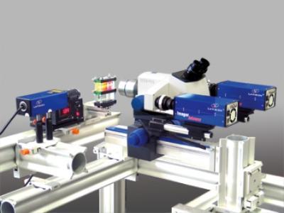
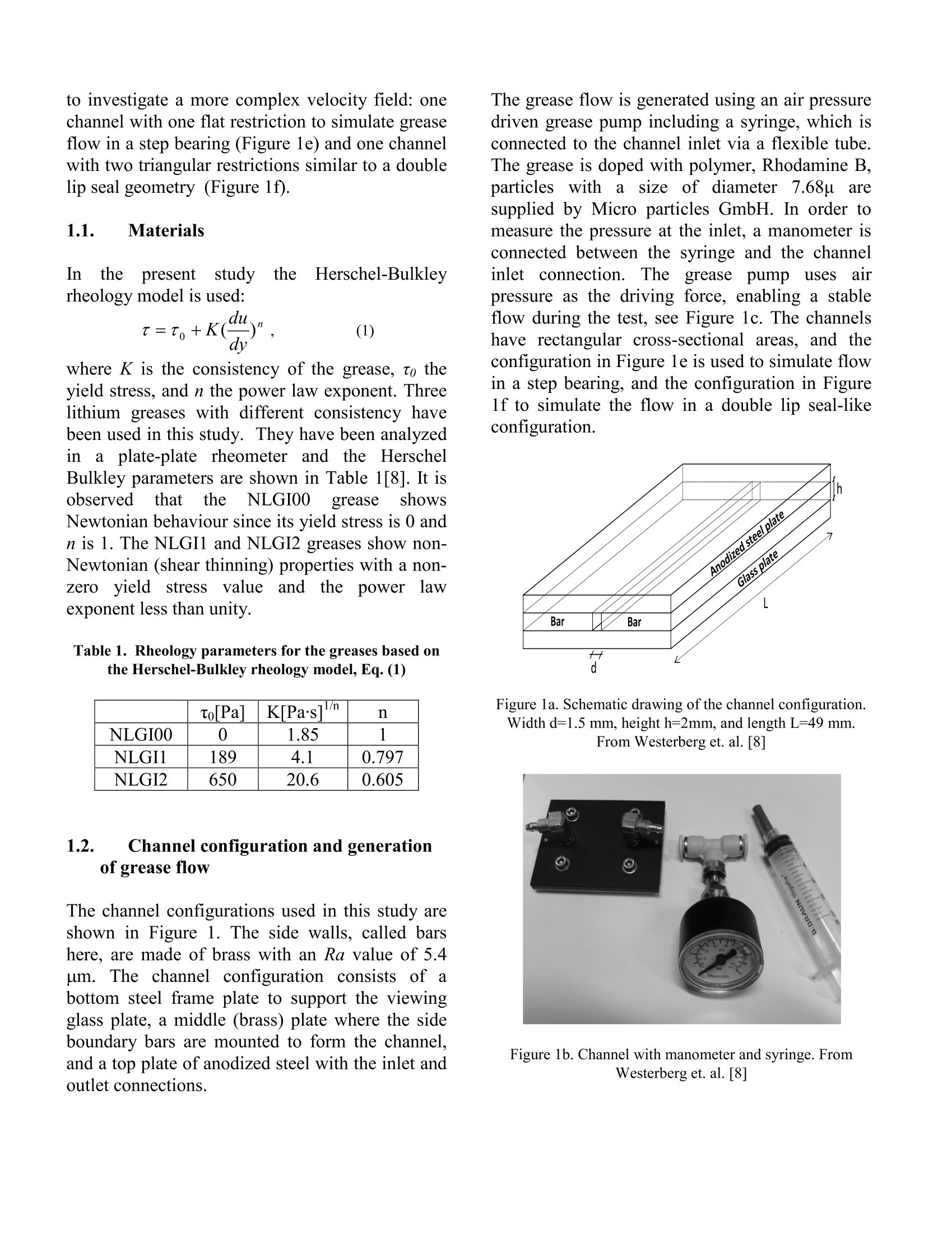
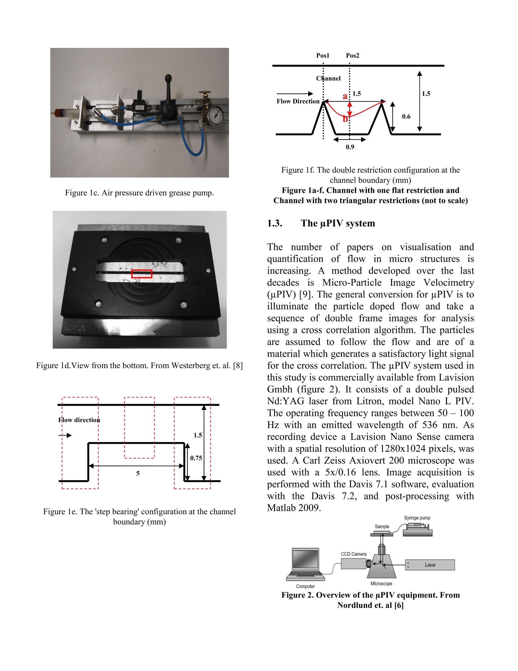
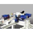
Measurements of Grease Flow in Channels with Restrictions usinguPIV J.LI,E. HOGLUND, LARS G. WESTERBERG,T.M. GREEN,T.S.LUNDSTROM,P.M. LUGT,P. BAART 1 Division of Machine Elements, Lulea University of Technology, SE-971 87 Lulea, Sweden 2 Division of Fluid Mechanics, Lulea University of Technology, SE-971 87 Lulea, Sweden 3 SKF Engineering & Research Center, Nieuwegein, The Netherlands Corresponding authors’emailadress: Erik.Hoglund@ltu.se Abstract: Grease is commonly used to lubricate various machine components such as rolling elementbearings, open gears etc. Better understanding of the flow properties of grease will contribute tounderstanding the lubrication mechanism in bearings and flow in lubrication systems. In an earlier paperMicro Particle Image Velocimetry (uPIV) techniques were used to study the flow in a rectangular channel.The present paper is an extension of this work where restrictions were applied in such a channel, whichcreates a much more complex velocity field. The grease is seeded with fluorescent particles, which areilluminated by a double-pulsed laser. The test geometries that are used in this study are a channel with oneflat restriction and one with two flow restrictions in a similar channel. The stationary grease mass-flow andthe two dimensional velocity fields have been monitored for different pressure drops. For the channel withone flat restriction, the flow was measured to be symmetric at the inlet and outlet, and the distance for theflow to fully develop is comparable with the height of the channel; Slow motion was followed near the stepcorner at the inlet. For the channel with two flow restrictions, the vector profiles show that the maximumvelocity appears at the restrictions; In-between the two restrictions, a part of the grease is not moving. Thisparticularly applies to cases with low-pressure drop and where high consistency grease was used. Key words: grease flow; uPIV; seal; step bearing; rheology 1. INTRODUCTION Compared to lubricating oil, grease hasslsomeadvantages, e.g. easy to use since it does not easilyleak out, it acts as a seal, shows low friction andmay have anticorrosion properties [1]. For thisreason.l, greases are commonly applied forlubricating rolling element bearings. Unlike oil,grease consists of a multi-phase system (oil,additives and thickener) giving it a consistency,which is defined from the grease matrix resistingpositional change [2] until the yield stressisreached. Grease lubricated rolling element bearings oftenrun under starved elastohydrodynamic (EHD)lubrication conditions [3]. In general, the study ofgrease is very important to understand greaselubricationin rollingbearings (duringthechurning phase), lubrication systems and bearingseals, but also to sliding bearings. Radulescu et. al.[4,5] have investigated the flow in a Rayleigh stepbearinggeometrymainly with simulationmethods. Micro Particle Image Velocimetry method (uPIV)has been proven a good method to study flows [6-8]. The objective of this study is to betterunderstand grease flow in a channel with differenttypes of restrictions. Two new channels were used to investigate a more complex velocity field: onechannel with one flat restriction to simulate greaseflow in a step bearing (Figure 1e) and one channelwith two triangular restrictions similar to a doublelip seal geometry (Figure 1f). 1.1. Materials Inn thepresentstudy theHerschel-Bulkleyrheology model is used: where K is the consistency of the grease, to theyield stress, and n the power law exponent. Threelithium greases with different consistency havebeen used in this study. They have been analyzedinaplate-plate rheometer and the HerschelBulkley parameters are shown in Table 1[8]. It isobserved that theNLGIO0 greaseshowsNewtonian behaviour since its yield stress is 0 andn is 1. The NLGI1 and NLGI2 greases show non-Newtonian (shear thinning) properties with a non-zero)yield stress value and thepower lawexponent less than unity. Table 1. Rheology parameters for the greases based onthe Herschel-Bulkley rheology model,Eq. (1) to Pa| KPas1/n n NLGIoo o 1.85 NLGI1 189 4.1 0.797 NLGI2 650 20.6 0.605 1.2. Channel configuration and generationof grease flow The channel configurations used in this study areshown in Figure 1. The side walls, called barshere, are made of brass with an Ra value of 5.4um.The channel configuration consists of abottom steel frame plate to support the viewingglass plate, a middle (brass) plate where the sideboundary bars are mounted to form the channel,and a top plate of anodized steel with the inlet andoutlet connections. The grease flow is generated using an air pressuredriven grease pump including a syringe, which isconnected to the channel inlet via a flexible tube.The grease is doped with polymer, Rhodamine B,particleswithalsize of diameter 7.68p aaresupplied by Micro particles GmbH. In order tomeasure the pressure at the inlet, a manometer isconnected between the syringe and the channelinletconnection..The grease pump)uses airpressure as the driving force, enabling a stableflow during the test, see Figure 1c. The channelshave rectangular cross-sectional areas, and theconfiguration in Figure 1e is used to simulate flowin a step bearing, and the configuration in Figure1f to simulate the flow in a double lip seal-likeconfiguration. Figure 1a. Schematic drawing of the channel configuration.Width d=1.5 mm, height h=2mm, and length L=49 mm.From Westerberg et. al.[8] Figure 1b. Channel with manometer and syringe. FromWesterberg et. al.[8] Figure 1c. Air pressure driven grease pump. Figure 1d.View from the bottom. From Westerberg et. al. [8] Figure 1e. The 'step bearing'configuration at the channelboundary (mm) Posl Pos2 Figure 1f. The double restriction configuration at thechannel boundary (mm) Figure 1a-f. Channel with one flat restriction andChannel with two triangular restrictions (not to scale) 1.3. The uPIV system The number of papersonvisualisationi andquantification of flow in microstructuresisincreasing. A method developed over the lastdecadesisMicro-Particle Image Velocimetry(uPIV) [9]. The general conversion for uPIV is toilluminate the particle doped flow and take asequence of double frame images for analysisusing a cross correlation algorithm. The particlesare assumed to follow the flow and are of amaterial which generates a satisfactory light signalfor the cross correlation. The uPIV system used inthis study is commercially available from LavisionGmbh (figure 2). It consists of a double pulsedNd:YAG laser from Litron, model Nano L PIV.The operating frequency ranges between 50 - 100Hz with an emitted wavelength of 536 nm. Asrecording device a Lavision Nano Sense camerawith a spatial resolution of 1280x1024 pixels, wasused. A Carl Zeiss Axiovert 200 microscope wasused with a 5x/0.16 lens. Image acquisition isperformed with the Davis 7.1 software, evaluationwith the Davis7.2, and post-processing withMatlab 2009. Figure 2. Overview of the pPIV equipment.FromNordlund et. al[6] The results are presented mainly in terms of vectorfield plots and velocity profiles. Some morefigures are used in order to describe the resultsmore clearly. Three pressures between 0.3-2.5 barhave been applied to thegreases. Thesearereferred to low, medium and high pressurerespectively. This was done in order to see howthe flow rate changes with pressure. The flowrates were derived by integrating the velocity fromthe top of the restriction to the top of the channelat position 1 (Figure 1f). 2.1. Channel with one flat restriction For the channel with one flat restriction, threepositions are selected for measurements: inlet.steady flow on the step and outlet, which is shownin Figure le. Figure 3 shows some examples ofmeasured velocity fields for the NLGI1andNLGI2 grease. As expected, the velocity increasesas grease flows into the narrow channel, andexhibits a constant (plug flow) profile across thestep (Figure 3b), and then decreases at the exit ofthe restriction. The velocity profiles at differentpositions in the inlet and outlet zones wereanalyzed in more detail and are shown in Figure 4.In this figure, the different plotted velocities arethose measured at different positions, where thecolours of the line-plots correspond to those of thelines in figure 3. At the inlet, the grease velocitydistribution changes gradually from a wide plugflow to a more parabolic flow, inverted at theoutlet. This indicates that the yield stress isreached in a large part of the restriction. Thedistance for the flow to develop from a widesteady plug flow to a fully developed narrowparabolic channel flow (and the other way around)was defined as the transition zone and has beencalculated for both inlet and outlet zones, and theresults are similar: 1.26 mm as shown in Figure 3aand c. The transition zone is between 1.2-1.5 mmfor all three greases for pressure drops. c) Figure3. Averaged velocity field for high pressure: a)NLGI2 at inlet b) NLGI1 steady flow at the step c)NLGI2 outlet O:5 b) Figure 4. Velocity profile at different position denoted bydifferent colors respectively: a) inlet Figure 3a; b) outlet Figure 3c Itis observed that there are slowly movingparticles near the step bottom corner at the inlet,the area shown in Figure 5, which is defined as thestagnant core by Radeluscu et al. [4,5]. Toinvestigate this phenomenon, a zoomed area withparticles is studied. Only qualitativemeasurements are done since the velocity of theparticles at the corner is very slow compared tothe main plug flow in the channel, making itdifficult to calculate the low velocities near thecorner. From the observations of all tests it isconcluded that the particles followed the mainflow along the border of the stagnant corner areaand passed through the step without moving intothe stagnant corner as the blue arrows indicate.Within this stagnant corner area, it is observed thatthe NLGIOo grease at high velocity, exhibitsminimal circulation, as the red arrows indicate. Tests on the NLGI1 grease with an extra high flowrate also shows this circulating flow but withseveral small vortices. The appearance of vorticescan be coupled to the shear stress, which makesthe grease flow for values higher than the yieldstress. Therefore, it is likely that this circulatingflow within the stagnant corner area will onlyoccur with high enough stresses, i.e. at higher flowrates. No vortices could be detected at the outlet. Figure 5. Close up view of the inlet corner of the flat step,NLGI00 Grease. 2.2. Double restrictions channel Considering the channel configuration withdouble restrictions, the maximum flow velocity islocated above the two restrictions. As expected, ahigh-pressure drop resulted in a high velVCo1c0ity(Figures 6a and b). From Figure 6b it can beobserved that grease flows closer to the boundarybetween the two restrictions due to the highvelocity. For the NLGI00 grease, a flow can beobserved down to the bottom between the tworestrictions (Figure 6c). Mean velocity field Figure 6. The averaged vector field for a) NLGI2 greaseat low pressure; b) as in a) but with high pressure; c)NLGI00 grease at high pressure Figure 7 shows the velocity profiles for threegreases at position 1 and position 2 (Figure 1f).More tests for NLGI1(0.3-2.5bar) and NLGI2(0.5-4bar) have been done in order to investigate theflow depth (discussed later). When comparingvelocity profiles for the three greases over the firstrestriction (position 1 in Figure 1f), it can be seenthat NLGI00 grease has a more Newtonian flowprofile compared to the NLGI1- and NLGI2grease, i.e. the velocity profile of the NLGI00grease has a parabolic-shape. At low flow rate(low pressure drop), the velocity profiles of theNLGI1- and NLGI2 grease exhibit nearly a plugflow over the first restriction, which1isS 1inaccordance with the work of Westerberg et al. [8]; as the flow rate increases, the velocity profilesbecome1moreeparabolic, corresponding toNewtonian behaviour. The velocity profiles at the middle of the tworestrictions (position2 in Figure 1f) indicate thatthere are regions (marked in figure 6a) with nomotion of the grease. Ass the NLGI numberdecreases or the flow rate increases, grease flow isdetectable further down in the space between thetwo restrictions. In order to investigate this, theterm flow depth is introduced. As shown in Figure1f, the red curve presents the border between themoving grease and the seemingly stationarygrease, and the flow depth is defined by thedistance between the straight line of the two tipsof the two restrictions and the red curve at position2 (the red arrow line a-b). To calculate the flowdepth, the velocity profiles in Figure 7 were used.The point a in Figure 1f is defined as the bottompoint of the velocity profile at position 1. Todetermine point b in Figure 1f, a velocity of 9x10m/s was chosen for all three greases, below whichthe grease flow velocity was assumed negligible.The irregular velocity profiles at lower flow rateshave not been included due to the noise in thevelocity signal. The relationship between flowdepth and flow rate is shown in Figure 8. For theNLGI00 grease, the flow depth is linear with flowrate as would be expected for Newtonian fluids[10]. The flow depths of NLGI00 are higher thanthat of NLGI1 and NLGI2 in all the tests andreaches to the bottom at flow rate 5.2 m /s (thedistance from the tip of the restrictions to thebottom is 0.6mm, Figure1f); more tests are neededto investigate flow depth at low flow rate ofNLGI00 grease. For NLGI1 and NLGI2 grease,the flow depth and the flow ratehavealogarithmic relationship; there is no penetrationdepth even though there is a flow rate whenextrapolating the logarithmic line to theXcoordinate. This could be explained by therheological behaviour of the grease, i.e. the yieldstress of the grease. Internal binding forces givegrease a solid character [2], until the externalstressesare beyond the yield stress, then thegrease starts to flow. At low flow rates the flowdepth is zero since the shear stress between the moving grease and the grease trapped in the area between the two restrictions is lower than theyield stress. Only when the flow rate is highenough, the grease between the two restrictionswill start to move, which results in a flow depth.As a result, high consistency grease needs a highflow rate to induce flow down into the areabetween the two restrictions. If a contaminant particle is located in thestationary grease between the two restrictions at arelatively low velocity, the particle will start toflow and pass through the second restriction whenthe flow velocity increases, i.e. the flow depthincreases.Thereforeiincreasingggreaseflowvelocities endangers contaminant particles thatpreviously have settled in corners or in-betweenrestrictions, to flow again. From Figure 3c, when the grease flows throughthe restriction, it becomes fully developed aftersome distance (1.26mm). Thus, it is expected inthe double restrictions channel that, when thedistance between the two restrictions increases.the grease flow will further develop and the flowdepth will increase. a) 05 Velocity [m/s] c) Figure 7. Velocity profiles captured from Pos 1 (solidlines) and Pos 2 (dashed lines) as described in figure 1f:a) NLGI00; b) NLGI1; c) NLGI2. q is the integrated flowacross the channel for each position. Figure 8. Flow depth vs. integrated flow rate across thechannel for NLGI00, NLGI1 and NLGI2. 3.l. CONCLUSIONS 1. The grease flow is symmetric in the inlet andoutlet zones for all three grease. The transitionzones are about 1.2-1.5 mm, comparable to theheight of the channel before the step, which is 1.5mm. 2. In the corner area before the restriction, no flowis observed which is defined as the stagnant cornerarea, for NLGI2 greases while for NLGI00 andNLGI1 grease, at high velocity, a small circulationflow has been discovered. 3. NLGI00 grease exhibits a parabolic velocityprofile, (Newtonian fluid behavior) while the flowprofile of higher NLGI number greases has a plugflow shape. As the velocity increases, these flowprofiles change to more parabolic shapes. 4. The flow depth, i.e. the penetration of flow in-between the two restrictions, is linear with flowrate for the NLGI00 grease and follows a powerlaw with flow rate for NLGI1 and NLGI2 greases:the higher the velocity, the deeper the flow depth. 5. The grease flow will develop deeper in-betweenthe two restrictions if the distance between them islarger. 4..ACKNOWLEDGEMENTS The authors would like to thank the SwedishScience Council (VR) for its financial support ofthe work presented in this paper. We also acknowledge Mr. Tore Serrander, fordesigning and constructing the air pressure drivengrease pump. 5.i. REFERENCES 1. Lugt, P.M., A Review on Grease Lubrication inRolling Bearings. Tribology Transactions 52 (4),2009, 470-480. 2. Mortier, R.M., Orszulik, S.T., Chapter 11,Chemistry & Technology of Lubricants, firstedition, VCH Publishers, Inc., New York, 1994,255-268 3. Cann, P.M.E., Thin-film grease lubrication.Proceedings of the Institution of MechanicalEngineers Part J-Journal of Engineering Tribology213 (J5), 1999,405-416. 4. Radulescu, A.V., Vasiliu, F.Simplified calculusmethod for a grease-lubricated Rayleigh stepbearing, Lubrication Science 11 (3), 1999, 271-284. 5. Radulescu, A.V., Bonneau, D., Hajjam, M., Atheoretical study of two-dimensional grease flowinregions withdiscontinuities. LubricationScience 15 (2), 2003, 163-171. ( 6. N ordlund, M. F ernberg, S.P. and Lundstrom, T.S., “Particle Deposition Mechanisms duringProcessing of Advanced Composite M a terials”,Composites: Part A, 38 (10), 2007, 2182-2193 ) ( 7.Nordlund. M. and L undstrom. T.S.. Investigation of Transien t Flow Behaviour in Dual-Scale PorousS M edia with M icro P a rticleImage V elocimetry, Polymer CompositesPublished on-line (2010), DOI 10.1002/pc ) ( 8. Westerberg, L.G., Lundstrom, T.S., Hoglund E.,Lugt, P .M., Investigation of g rease flow in arectangular channel i ncluding w all s l ip ef fectsusing micro Particle Image Velocimetry, T ribology Transactions, Accepted (2010) ) ( 9. Wereley, S.T. and M einhart, C.D., "RecentAdvances in M icro-Particle Image Velocimetry", Annual Review of F luid Mechanics. 2010.42:557-576 ) ( 10.Barnes, H.A., Chapter 6, A HANDBOOK OF ELEMENTARYRHEOLOGY, first e dition.Institut e o f Non-Newtonian F luid1 Mechanics. University of Wales, 2000, 25-30 )
确定
还剩6页未读,是否继续阅读?

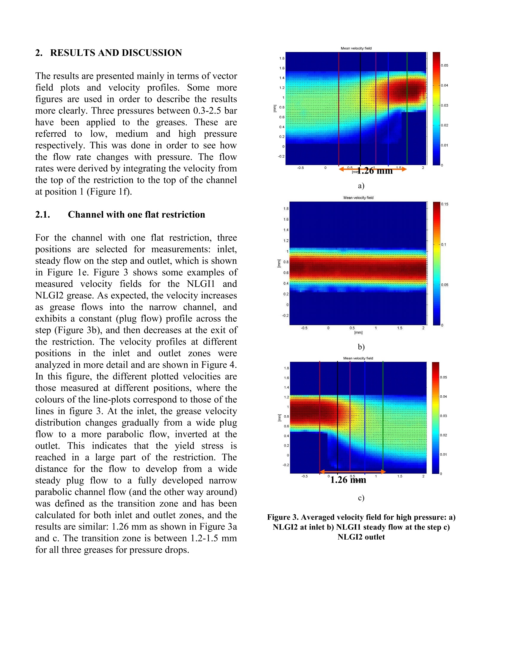
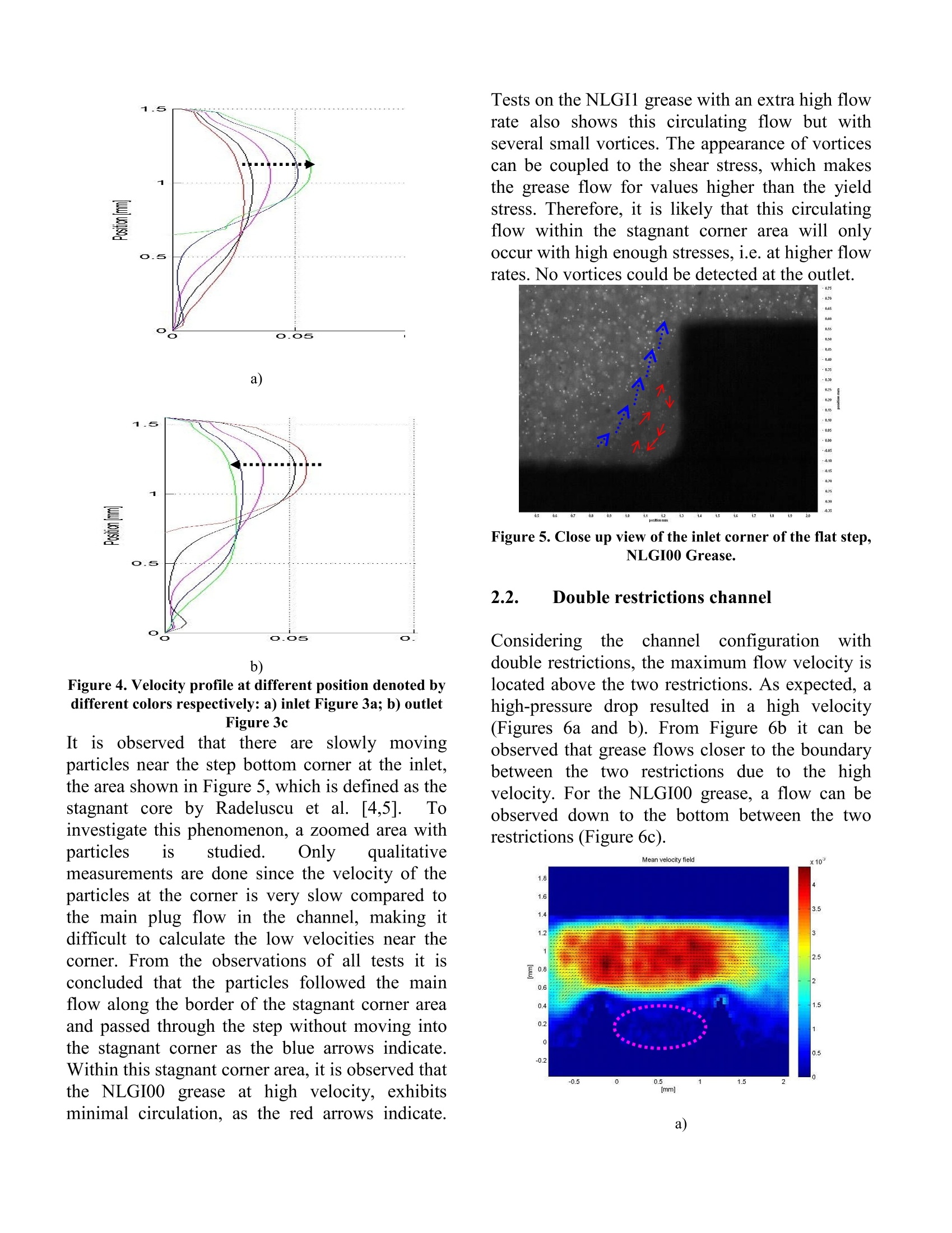
产品配置单
北京欧兰科技发展有限公司为您提供《润滑油中微尺度流场,速度场检测方案(粒子图像测速)》,该方案主要用于润滑油中微尺度流场,速度场检测,参考标准--,《润滑油中微尺度流场,速度场检测方案(粒子图像测速)》用到的仪器有显微粒子成像测速系统(Micro PIV)
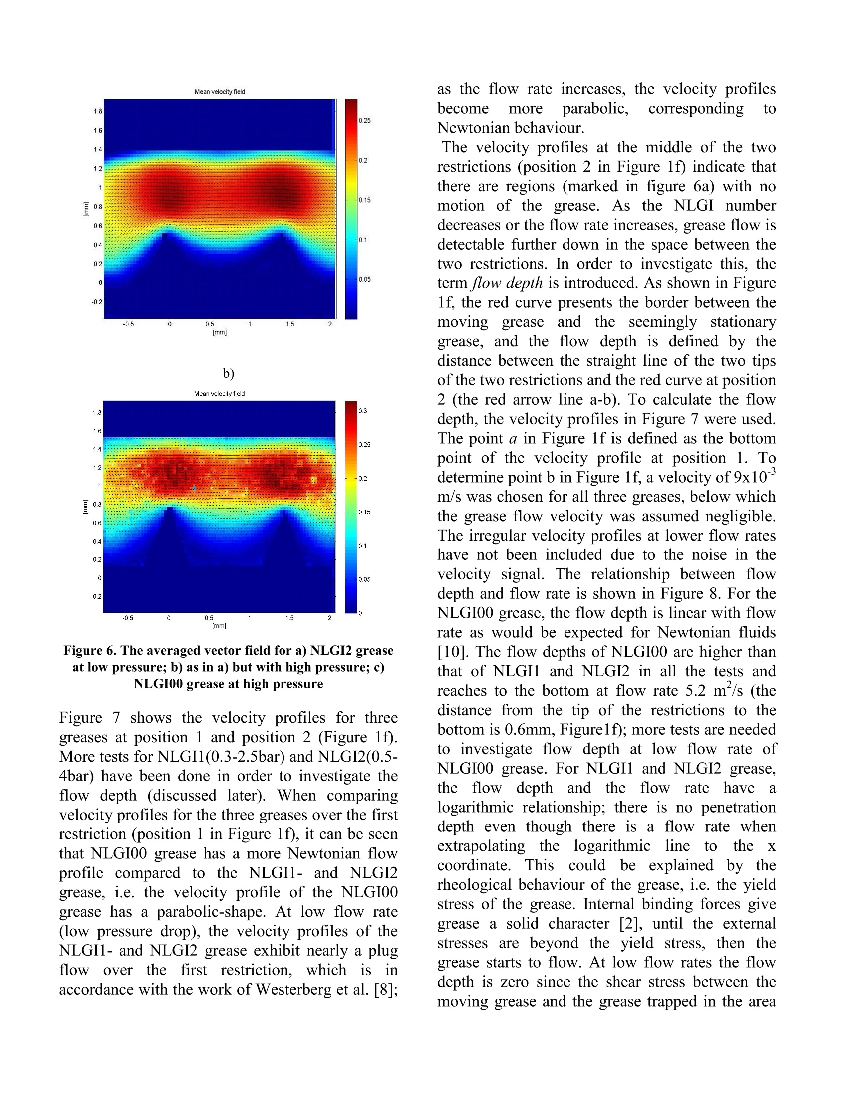
推荐专场


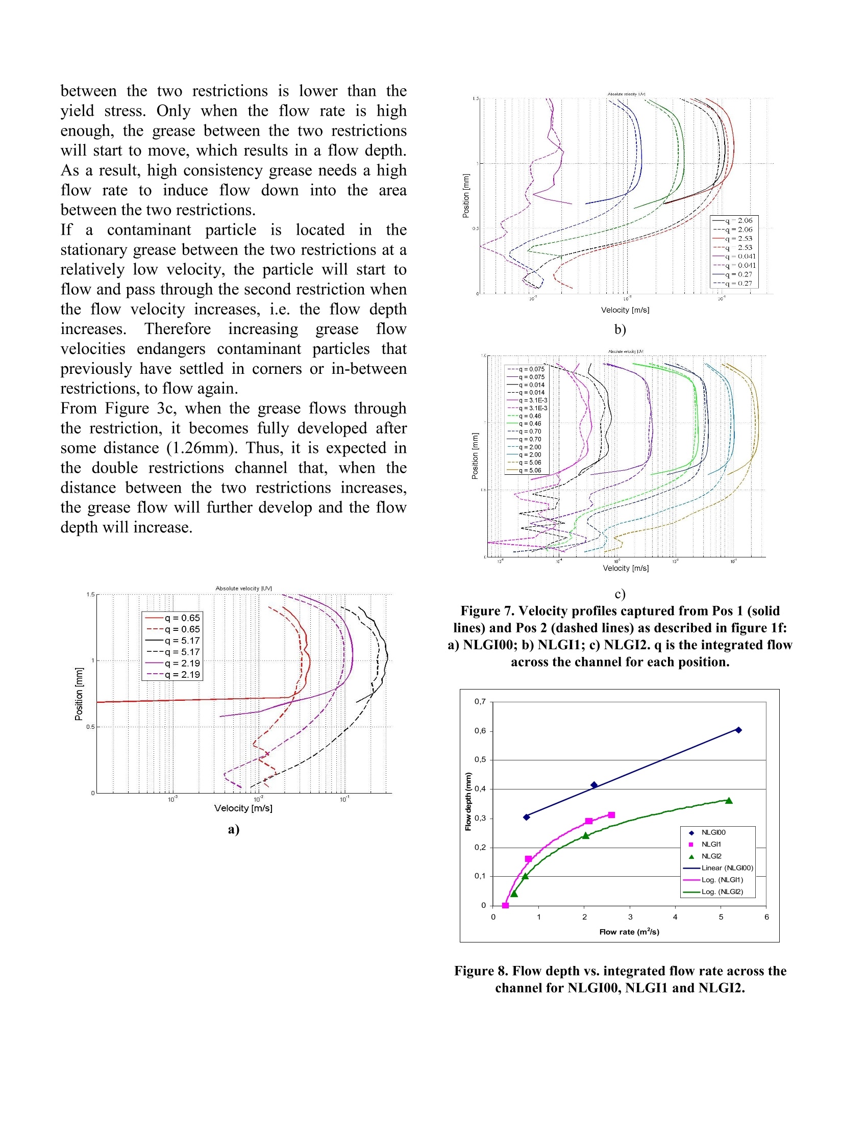
相关方案
更多
该厂商其他方案
更多