


方案详情
文
This article concerns the flame dynamics of a bluff body stabilized turbulent premixed flame as it
approaches lean blowoff. Time resolved chemiluminescence imaging along with simultaneous particle
image velocimetry and OH planar laser-induced fluorescence were utilized in an axisymmetric bluff body
stabilized, propane-air flame to determine the sequence of events leading to blowoff and provide a quantitative
analysis of the experimental results. It was found that as lean blowoff is approached by reduction
of equivalence ratio, flame speed decreases and the flame shape progressively changes from a conical to a
columnar shape. For a stably burning conical flame away from blowoff, the flame front envelopes the
shear layer vortices. Near blowoff, the columnar flame front and shear layer vortices overlap to induce
high local stretch rates that exceed the extinction stretch rates instantaneously and in the mean, resulting
in local flame extinction along the shear layers. Following shear layer extinction, fresh reactants can pass
through the shear layers to react within the recirculation zone with all other parts of the flame extinguished.
This flame kernel within the recirculation zone may survive for a few milliseconds and can reignite
the shear layers such that the entire flame is reestablished for a short period. This extinction and
reignition event can happen several times before final blowoff which occurs when the flame kernel fails
to reignite the shear layers and ultimately leads to total flame extinguishment.
方案详情

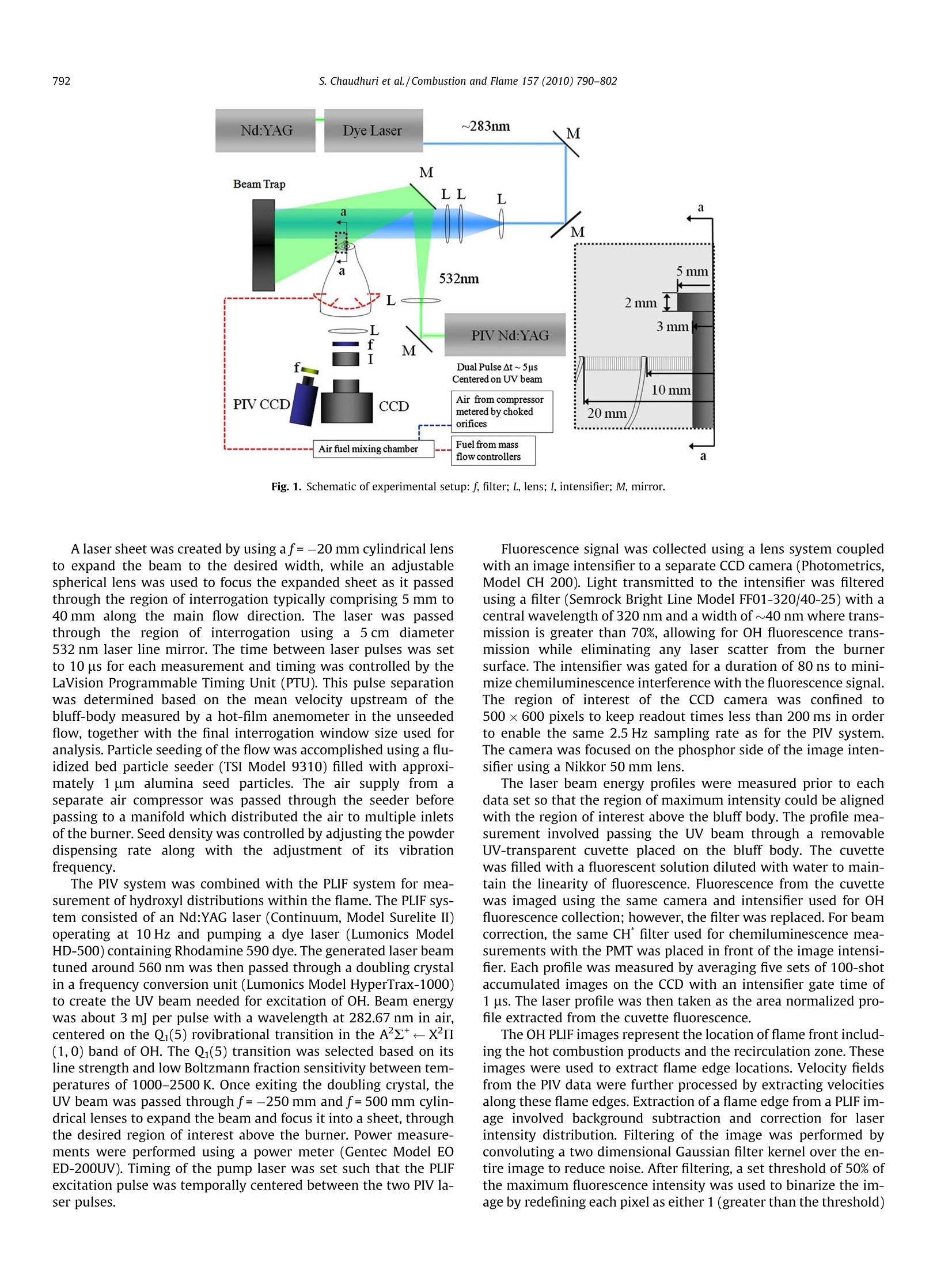
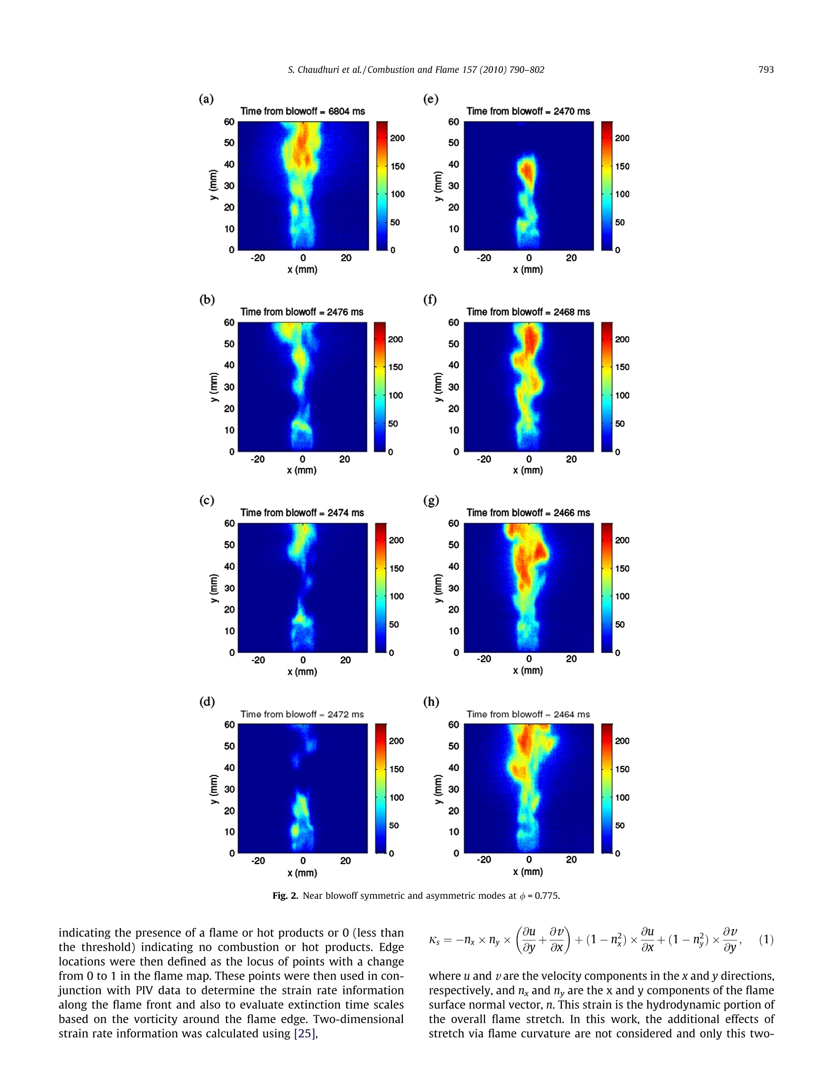
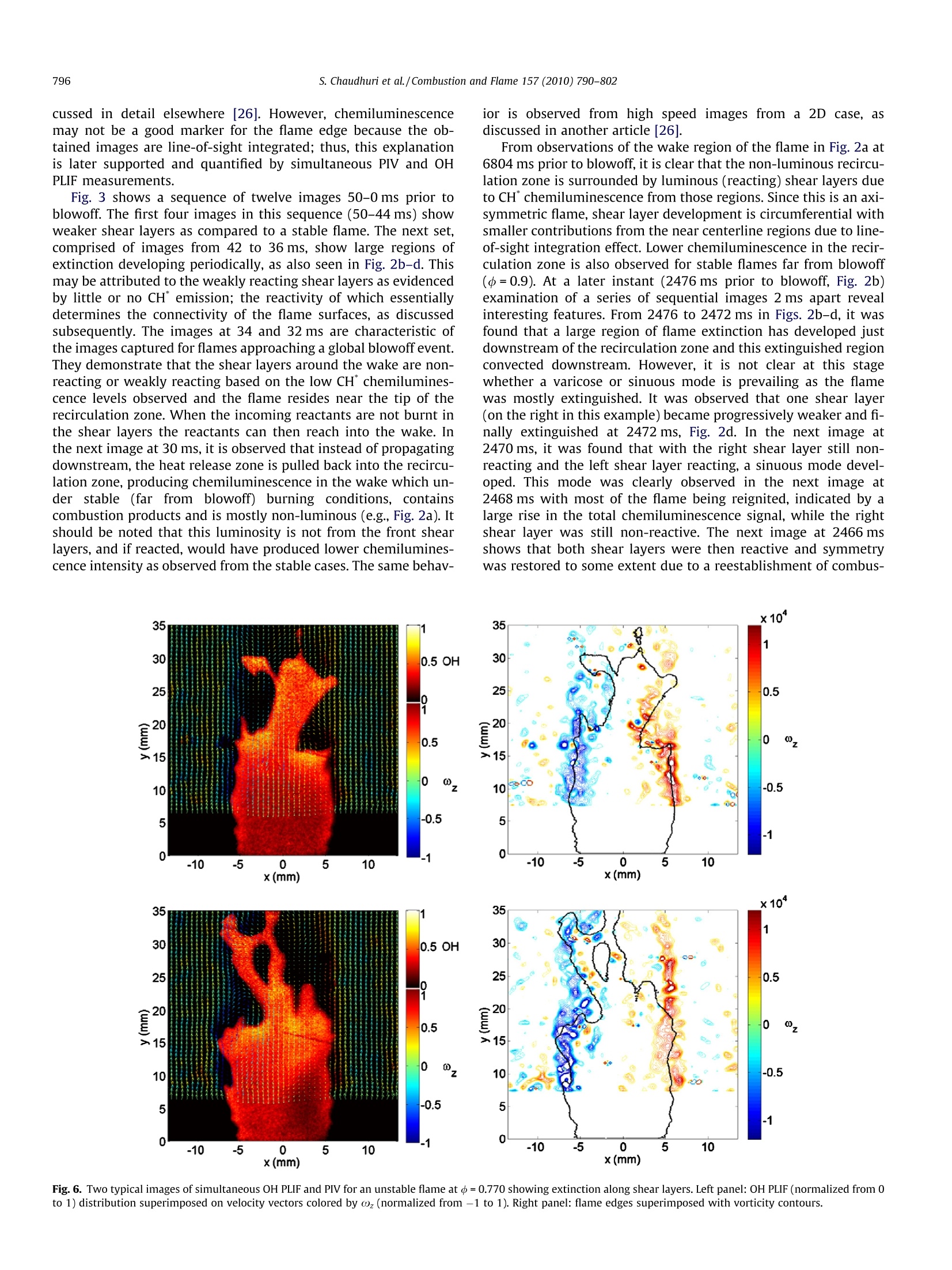
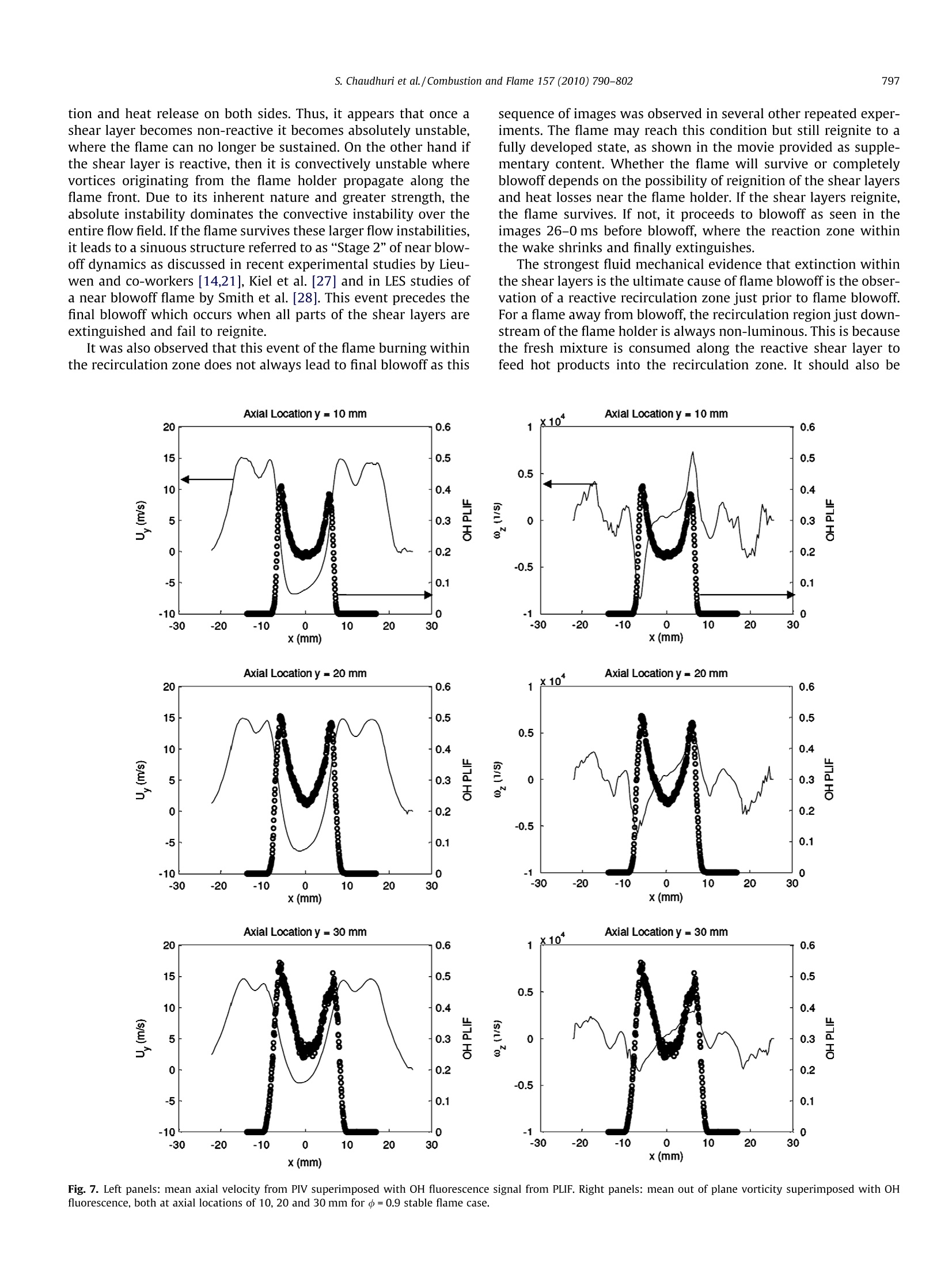
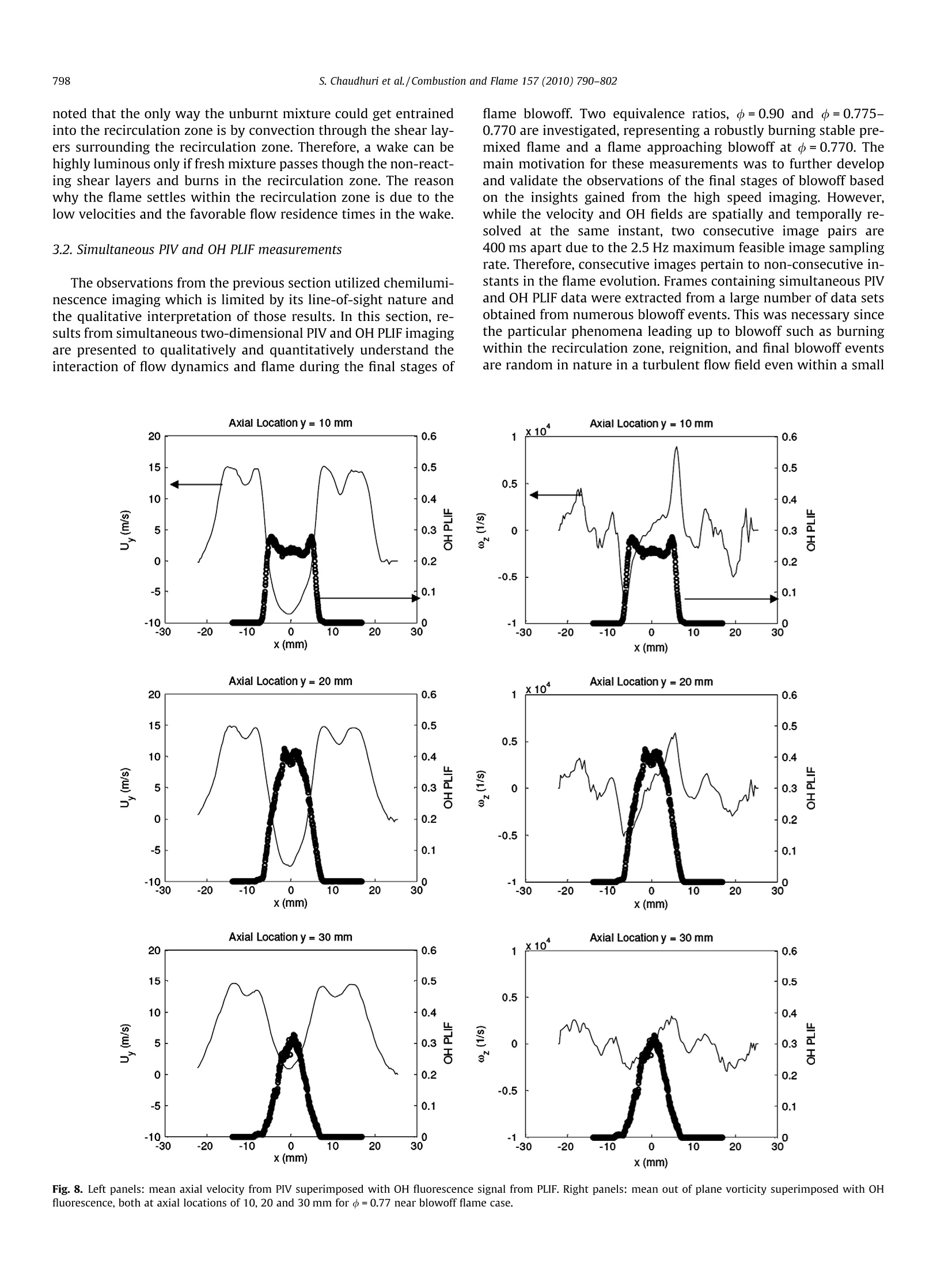
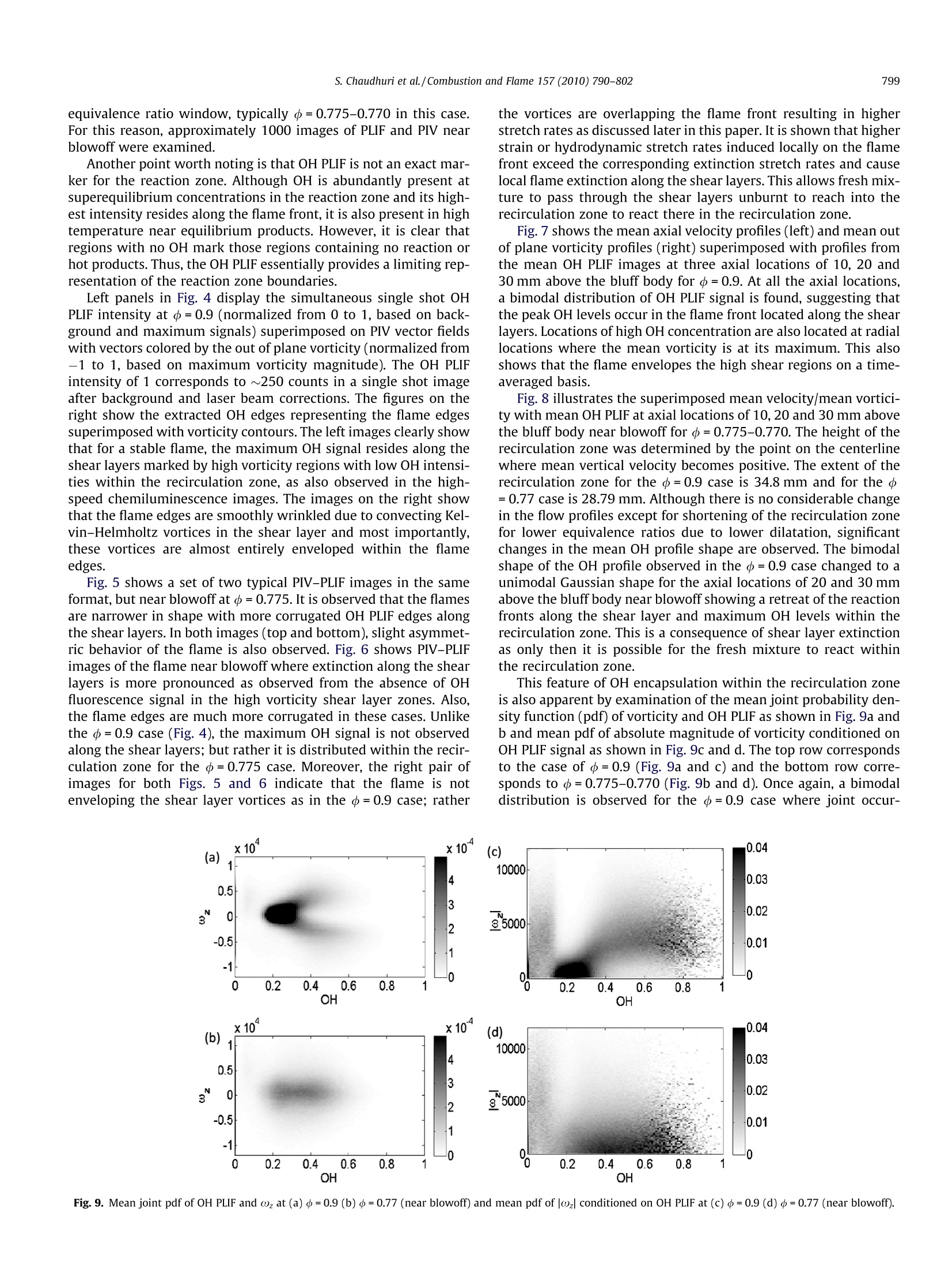
Combustion and Flame 157 (2010)790-802Contents lists available at ScienceDirectCombustion and Flame 791S. Chaudhuri et al./Combustion and Flame 157 (2010)790-802 doi:10.1016/j.combustflame.2009.10.020 ELSEVIER journalhomepage: www.elsevier.com/locate/combustflame Blowoff dynamics of bluff body stabilized turbulent premixed flames Swetaprovo Chaudhuri, Stanislav Kostka, Michael W. Renfro, Baki M. Cetegen * Department of Mechanical Engineering, University of Connecticut, 191 Auditorium Road, U-3139, Storrs, CT 06269, USA ARTICLE:INFO ABSTRACT Article history:Received 25 June 2009Received in revised form 14 August 2009Accepted 30 October 2009 Available online 8 January 2010 Keywords:Bluff-body premixed flamesPIVPLIF Blowoff and extinction This article concerns the flame dynamics of a bluff body stabilized turbulent premixed flame as itapproaches lean blowoff. Time resolved chemiluminescence imaging along with simultaneous particleimage velocimetry and OH planar laser-induced fluorescence were utilized in an axisymmetric bluff bodystabilized,propane-air flame to determine the sequence of events leading to blowoff and provide a quan-titative analysis of the experimental results. It was found that as lean blowoff is approached by reductionof equivalence ratio, flame speed decreases and the flame shape progressively changes from a conical to acolumnar shape. For a stably burning conical flame away from blowoff, the flame front envelopes theshear layer vortices.Near blowoff, the columnar flame front and shear layer vortices overlap to inducehigh local stretch rates that exceed the extinction stretch rates instantaneously and in the mean, resultingin local flame extinction along the shear layers. Following shear layer extinction, fresh reactants can passthrough the shear layers to react within the recirculation zone with all other parts of the flame extin-guished.This flame kernel within the recirculation zone may survive for a few milliseconds and can reig-nite the shear layers such that the entire flame is reestablished for a short period. This extinction andreignition event can happen several times before final blowoff which occurs when the flame kernel failsto reignite the shear layers and ultimately leads to total flame extinguishment. @ 2009 The Combustion Institute. Published by Elsevier Inc. All rights reserved. 1. Introduction Premixed flame stabilization in high speed flows has been animportant topic of inquiry in combustion research over the pastseveral decades. Practical applications include flame stabilizationin afterburners of military aircraft, gas turbine combustors andindustrial furnaces. Flame stabilization schemes that have beenwidely used in such applications primarily involve bluff-bodyand swirl stabilization. In this work, we focus on bluff body stabil-ization. The physical processes that anchor a premixed flame be-hind a bluff body flame holder involve the combustible mixturebeing in contact with the hot combustion products residing inthe recirculation zone and continuous ignition of the incomingmixture in shear layers bounding the recirculation zone. The globalflame holding characteristics have been investigated in a numberof seminal works by Zukoski and Marble [1-3], Williams et al.[4], and Longwell [5]. In these studies, a flame blowoff criterionwas established for flame holding in uniformly premixed gases,and the effects of different bluff-body geometries on flame holdingwere identified. Among other investigations, Plee and Mellor [6],Rao and Lefebvre[7], and Rizk and Lefebvre [8] considered the leanblowoff limits for different combustible mixtures, bluff bodygeometries, and variable pressure and temperature. In some of ( * C ( orresponding a u thor. Fax: +1 8 60 486 5088. ) ( E -mail a ddress: cetegen @ engr.uconn.edu (B . M. Cetegen). ) these studies, effects of fuel droplet vaporization and mixing wereconsidered as these issues relate to aircraft gas turbine flameholding. Longwell [5] suggested that blowoff occurs when it is not pos-sible to balance the rate of entrainment of reactants into the recir-culation zone, viewed as a well-stirred reactor, and the rate ofburning. An alternative view is that the contact time between thecombustible mixture and hot gases in the shear layer must exceeda chemical ignition time [9-11]. According to Zukoski [9], ignitionof the incoming fresh reactant mixture occurs in the shear layer asit mixes with combustion products from the recirculation zone be-hind the bluff body. Several studies have proposed a flamelet baseddescription of local extinction by excessive flame stretch as sug-gested by Yamaguchi et al. [12] and Pan et al.[13] and others. Lieu-wen and coworkers recently collected blowoff data from over fiftysources and developed correlations based on extinction time scalesand extinction stretch rates from Chemkin calculations [14].How-ever, the details of the blowoff mechanism particularly the flamedynamics just prior to blowoff still remain elusive. Recently, we studied experimentally the behavior of turbulentconical premixed flames anchored at their apex by a bluff bodyflame holder. These studies included flame blowoff characteristicsunder upstream flow oscillations [15] and spatial equivalence ratiogradients [16,17], their transfer function characteristics [17,18]and the effects of lateral flame confinement [19]. Although asignificant amount of research has focused on investigation of the blowoff mechanism in bluff body stabilized flames, a completephysical understanding of the final blowoff mechanism is still lack-ing. Significant contributions have been made recently by Nair andLieuwen [20,21] who characterized two stages of near blowoffevents. The first stage of flame blowoff is marked by localizedextinction along the flame sheet, namely the formation of flameholes, their convection along the flame, and their subsequent heal-ing towards a continuous flame surface. Although this stage acts asa marker towards flame blowoff, it has been suggested that theflame can survive indefinitely in this stage. The second stage ischaracterized by a more violent flapping of the flame front andan asymmetric mode of flame shape oscillations [16]. It shouldbe noted that in a non-reactive cold isothermal flow separated bya bluff body, a three dimensional helical mode of absolute instabil-ity dominates the flow field characterized by convection of asinuous vortex street, along with a weaker convective Kelvin-Helmholtz instability. For the two-dimensional case, the asymmet-ric vortex shedding is the well known von Karman vortex street.For axisymmetric cases, a helical mode of vortex shedding is ob-served. When viewed across a two dimensional projection, theyappear similar to the von Karman vortex shedding [22]. On theother hand, for a reactive flow with sufficiently high heat releaseacross the shear layers, shear layer generated vorticity is dampeddue to the effects of dilatation, production of baroclinic vorticity,and increase of viscosity. Thus, for a stable and robustly burningflame, absolute instability and the associated asymmetry is lostand only convective instability in the form of symmetric Kelvin-Helmholtz vortices appear along the shear layer. It has been observed experimentally and also demonstratedcomputationally that a reversal to asymmetry can occur near flameblowoff or flames burning at low dilatation ratios [23]. Asymmetricflame behavior has been attributed to near unity global tempera-ture ratio levels [23], although a wide variation exists in the re-ported values of temperature or density ratio thresholds. Thus,the parametric limits of the inception of asymmetry in the flowfield are not well established and likewise, the role of this asymme-try in the flame blowoff mechanism is not clear. In this article, we examine flame blowoff based on the flame/flow interaction obtained by time-resolved chemiluminescenceimaging and simultaneous particle imaging velocimetry (PIV) andOH planar laser-induced fluorescence (PLIF) imaging. The experi-ments show that near blowoff, extinction of the flame along theshear layers leads to reaction of fresh mixture within the recircula-tion zone, which normally contains combustion products for a sta-bly burning flame away from blowoff. The flame kernel survives forseveral milliseconds in the recirculation zone before annihilationof the entire flame, i.e. blowoff. This phenomenon of extinctionalong the shear layers is acknowledged to be a major cause ofblowoff, which occurs due to the induction of excessive stretchrates by the shear layer vortices coupling with the flame front asflame blowoff is approached. 2. Experimental method Two different experimen diagnostics were used for studying thebluff-body stabilized flames in the same axisymmetric burner usedin previous studies [16-19], the detailed schematic of which isshown in Fig. 1. The first one involved chemiluminescence imagingusing both a high speed camera and a photomultiplier tube (PMT)detector. The second involved a combined PIV-PLIF system used toextract velocity fields and qualitative OH distributions from whichflame positions and strain rates along flame boundaries weredetermined. The air flow was supplied by a 0.1 kg/s capacity compressor(Gardner-Denver, Model Electra-ECHQHE). The compressor air dis- charge was first dried by a refrigeration-type dryer (HankinsonModel 80200) and metered by a bank of critical flow orifices to ob-tain the desired air mass flow rate or nozzle exit velocity. Fuel(instrument grade propane, 99.5% purity) was metered using aset of mass flow controllers (Porter Instruments Model 202). Fueland air were premixed in a mixing chamber containing a seriesof perforated plates and baffles to completely mix the fuel andair streams before the mixture entered the axisymmetric con-toured burner nozzle through eight radial ports. Extensive mixingdiagnostics using Rayleigh scattering were utilized to measure thefuel concentration profile and to test for any non-uniformity of themixture. These results were presented in Fig. 3a of Ref.[16]. Thosemeasurements showed a uniform equivalence ratio profile for thepresent case of interest. A 10 mm disk shaped bluff body wasplaced at the exit of the 40 mm diameter nozzle outlet shown inthe inset in Fig. 1. All the results discussed in this paper correspond to experi-ments performed at an inlet velocity of Umean= 10 m/s with a tur-bulence intensity around 5% of the mean. These values are nearlyuniform along the radial direction, confirmed via hot-film ane-mometry measurements, [16]. The inlet temperature was 298 K.The Reynolds number was 6293 based on the diameter of thebluff-body,d=10 mm. For these conditions the DeZubay parame-ter [24] is 8.437 with the fuel to air ratio at blowoff being 0.049.This is in close agreement with the experiments performed byDezubay [24]. However, the DeZubay number is an empirical cor-relation that does not take into account the chemical time scalescomprehensively. As such the authors have adopted to use a cor-relation suggested by Shanbhogue et al. [14]. The lean blowoffequivalence ratio of the present study agrees very well with datafrom other sources with respect to this parameter. The Damkoh-ler number based on lip velocity is 2.5 with a corresponding Rey-nolds number of 6293. It falls very close to the linear trendlinegiven by Daolip=f(Re-0.67) and is within the limits of scatter inthe experiments reported by DeZubay[24]. For chemilumines-cence measurements, a monochromatic high speed camera, Mo-tion Scope (Redlake Imaging, Model 8000), optically coupled toa DEP-Gen II image intensifier was focused on the bluff-bodywake. Images were gathered at 500 frames per second. Gate tim-ing of the intensifier was controlled using a delay generator(Stanford Research System, Model DG535) with time gate widthset to 700 us. For acquisition at 500 Hz, the CCD size was reducedto 512x512 pixels. The images were continuously recorded intothe buffer for a maximum recording time of 8.192 s. The PMT,with a 432-nm bandpass filter and an objective lens was config-ured to view the bluff-body wake, providing a signal of the CH"chemiluminescence from this region. The PMT signal, gatheredat 5000 Hz, was recorded continuously and used to monitor theflame presence. When the flame extinguished for a period oflonger than 100 ms, an output trigger was sent to the camerato terminate image acquisition and store the images saved withinthe camera buffer. These images were representative of the finaleight seconds prior to complete blowoff. The simultaneous PIV-PLIF system was comprised of a standalone PIV system from LaVision Inc. The LaVision system consistedof a dual-cavity 50 mJ/pulse Nd:YAG laser (New Wave Solo PIV III),a frame-straddling 1024×1280 CCD camera (Flow Master3S), andDaVis 7.0 post-processing software. The PIV camera was coupledwith a Nikon 50-mm lens and a 532-nm optical line filter to allowfor imaging of scattered laser light downstream of the bluff body.In each case, 100 image pairs were collected for velocity averaging.The interrogation window for the PIV algorithm used a 16×16pixel region, based on an initial 128×128 fixed window, with50% overlap. Due to the readout time of both acquisition bufferson the frame-straddling PIV camera, the combined data acquisitionrate was 2.5 Hz. Fig. 1. Schematic of experimental setup: f, filter; L, lens; I, intensifier; M, mirror. A laser sheet was created by using a f=-20 mm cylindrical lensto expand the beam to the desired width, while an adjustablespherical lens was used to focus the expanded sheet as it passedthrough the region of interrogation typically comprising 5 mm to40 mm along the main flow direction. The laser was passedthrough the region of interrogation using a 5 cm diameter532 nm laser line mirror. The time between laser pulses was setto 10 ps for each measurement and timing was controlled by theLaVision Programmable Timing Unit (PTU). This pulse separationwas determined based on the mean velocity upstream of thebluff-body measured by a hot-film anemometer in the unseededflow, together with the final interrogation window size used foranalysis. Particle seeding of the flow was accomplished using a flu-idized bed particle seeder (TSI Model 9310) filled with approxi-mately 1 um alumina seed particles. The air supply from aseparate air compressor was passed through the seeder beforepassing to a manifold which distributed the ar to multiple inletsof the burner. Seed density was controlled by adjusting the powderdispensing rate along with the adjustment of its vibrationfrequency. The PIV system was combined with the PLIF system for mea-surement of hydroxyl distributions within the flame. The PLIF sys-tem consisted of an Nd:YAG laser (Continuum, Model Surelite II)operating at 10 Hz and pumping a dye laser (Lumonics ModelHD-500) containing Rhodamine 590 dye. The generated laser beamtuned around 560 nm was then passed through a doubling crystalin a frequency conversion unit (Lumonics Model HyperTrax-1000)to create the UV beam needed for excitation of OH. Beam energywas about 3 mJ per pulse with a wavelength at 282.67 nm in air,centered on the Qi(5) rovibrational transition in the A2++XII(1,0) band of OH. The Qi(5) transition was selected based on itsline strength and low Boltzmann fraction sensitivity between tem-peratures of 1000-2500 K. Once exiting the doubling crystal, theUV beam was passed through f=-250 mm and f=500 mm cylin-drical lenses to expand the beam and focus it into a sheet, throughthe desired region of interest above the burner. Power measure-ments were performed using a power meter (Gentec Model EOED-200UV). Timing of the pump laser was set such that the PLIFexcitation pulse was temporally centered between the two PlV la-ser pulses. Fluorescence signal was collected using a lens system coupledwith an image intensifier to a separate CCD camera (Photometrics,Model CH 200). Light transmitted to the intensifier was filteredusing a filter (Semrock Bright Line Model FF01-320/40-25) with acentral wavelength of 320 nm and a width of ~40 nm where trans-mission is greater than 70%, allowing for OH fluorescence trans-mission while eliminating any laser scatter from the burnersurface. The intensifier was gated for a duration of 80 ns to mini-mize chemiluminescence interference with the fluorescence signal.The region of interest of the CCD camera was confined to500×600 pixels to keep readout times less than 200 ms in orderto enable the same 2.5 Hz sampling rate as for the PIV system.The camera was focused on the phosphor side of the image inten-sifier using a Nikkor 50 mm lens. The laser beam energy profiles were measured prior to eachdata set so that the region of maximum intensity could be alignedwith the region of interest above the bluff body. The profile mea-surement involved passing the UV beam through a removableUV-transparent cuvette placed on the bluff body. The cuvettewas filled with a fluorescent solution diluted with water to main-tain the linearity of fluorescence. Fluorescence from the cuvettewas imaged using the same camera and intensifier used for OHfluorescence collection; however, the filter was replaced.For beamcorrection, the same CH" filter used for chemiluminescence mea-surements with the PMT was placed in front of the image intensi-fier. Each profile was measured by averaging five sets of 100-shotaccumulated images on the CCD with an intensifier gate time of1 us. The laser profile was then taken as the area normalized pro-file extracted from the cuvette fluorescence. The OH PLIF images represent the location of flame front includ-ing the hot combustion products and the recirculation zone. Theseimages were used to extract flame edge locations. Velocity fieldsfrom the PIV data were further processed by extracting velocitiesalong these flame edges. Extraction of a flame edge from a PLIF im-age involved background subtraction and correction for laserintensity distribution. Filtering of the image was performed byconvoluting a two dimensional Gaussian filter kernel over the en-tire image to reduce noise. After filtering, a set threshold of 50% ofthe maximum fluorescence intensity was used to binarize the im-age by redefining each pixel as either 1 (greater than the threshold) (a) (e) -20 0 20 -20 20 x(mm) x(mm) Fig. 2. Near blowoff symmetric and asymmetric modes at d=0.775. indicating the presence of a flame or hot products or 0 (less thanthe threshold) indicating no combustion or hot products. Edgelocations were then defined as the locus of points with a changefrom 0 to 1 in the flame map. These points were then used in con-junction with PIV data to determine the strain rate informationalong the flame front and also to evaluate extinction time scalesbased on the vorticity around the flame edge. Two-dimensionalstrain rate information was calculated using [25], where u and vare the velocity components in the x and y directions,respectively, and nx and ny are the x and y components of the flamesurface normal vector, n. This strain is the hydrodynamic portion ofthe overall flame stretch. In this work, the additional effects ofstretch via flame curvature are not considered and only this two- dimensional hydrodynamic stretch rate accessible via PIV iscomputed. Fuel-air mixture equivalence ratios of +=0.9 and +=0.775-0.770 were studied representing the flame conditions far fromand near blowoff cases, respectively. The flame edge map was used to determine the normal direc-tion for strain rate calculations. A scanning polynomial fit was per-formed along the flame edge in which the shape of the flame frontwithin a 20 pixel window centered about each edge point was usedto determine the normal components, nx and ny, of the flame sur-face. The direction of the normal vector was found such that thenormal vectors pointed into the region where no flame was present(toward 0 in the flame map). 3.1. High speed chemiluminescence imaging 3. Results In the following section, results from high speed imaging arefirst described, upon which the flame dynamics near blowoff areelucidated. These results are then analyzed and validated usingsimultaneous two-dimensional PIV and OH PLIF data. Experimentsreported here were performed at a mass averaged inlet velocity of10 m/s and a turbulence intensity of around 5% at the burnerexit as determined from hot-film anemometer measurements. High speed images of flame chemiluminescence without anyspectral filtering at 500 frames per second were obtained, asshown in Figs. 2 and 3. These example images were obtained nearflame blowoff at equivalence ratios decreasing from 0.775 in theinitial frames to 0.770 (the final blowoff point) in the laterimages. The experiments were repeated numerous times and sim-ilar observations to those presented here were found in each case.The flame appeared to exhibit a sinuous mode in some of theimages (Figs. 2e-f), a phenomenon observed in several prior stud-ies [19,20]. In the following paragraphs, an explanation of theswitch from the varicose (symmetrically distorted flame struc-tures) to sinuous (sinusoidal flame structures) flame shapes is gi-ven, which not only appears to be valid in this axisymmetric casebut also at higher Reynolds number two-dimensional cases dis- Time from blowoff = 50 ms Time from blowoff =42 ms Time from blowoff =34 ms Time from blowoff=26 ms 60 60 60 60 x(mm) x(mm) Fig. 4. Two typical images of simultaneous OH PLIF and PIV for a stable flame at o=0.9. Left panel: OH PLIF (normalized from 0 to 1) distribution superimposed on velocityvectors colored by ωz (normalized from -1 to 1). Right panel: flame edges superimposed with vorticity contours. x10 Fig. 5. Two typical images of simultaneous OH PLIF and PIV for an unstable flame at =0.775. Left panel: OH PLIF (normalized from 0 to 1) distribution superimposed onvelocity vectors colored by wz (normalized from-1 to 1). Right panel: flame edges superimposed with vorticity contours. cussed in detail elsewhere [26]. However, chemiluminescencemay not be a good marker for the flame edge because the ob-tained images are line-of-sight integrated; thus, this explanationis later supported and quantified by simultaneous PIV and OHPLIF measurements. Fig. 3 shows a sequence of twelve images 50-0 ms prior toblowoff. The first four images in this sequence (50-44ms) showweaker shear layers as compared to a stable flame. The next set,comprised of images from 42 to 36 ms, show large regions ofextinction developing periodically, as also seen in Fig. 2b-d. Thismay be attributed to the weakly reacting shear layers as evidencedby little or no CH" emission; the reactivity of which essentiallydetermines the connectivity of the flame surfaces, as discussedsubsequently. The images at 34 and 32 ms are characteristic ofthe images captured for flames approaching a global blowoff event.They demonstrate that the shear layers around the wake are non-reacting or weakly reacting based on the low CH" chemilumines-cence levels observed and the flame resides near the tip of therecirculation zone. When the incoming reactants are not burnt inthe shear layers the reactants can then reach into the wake. Inthe next image at 30 ms, it is observed that instead of propagatingdownstream, the heat release zone is pulled back into the recircu-lation zone, producing chemiluminescence in the wake which un-der stablee (far from blowoff) burning conditions, containscombustion products and is mostly non-luminous (e.g., Fig. 2a). Itshould be noted that this luminosity is not from the front shearlayers, and if reacted, would have produced lower chemilumines-cence intensity as observed from the stable cases. The same behav- ior is observed from high speed images from a 2D case, asdiscussed in another article [26]. From observations of the wake region of the flame in Fig. 2a at6804 ms prior to blowoff, it is clear that the non-luminous recircu-lation zone is surrounded by luminous (reacting) shear layers dueto CH* chemiluminescence from those regions. Since this is an axi-symmetric flame, shear layer development is circumferential withsmaller contributions from the near centerline regions due to line-of-sight integration effect.Lower chemiluminescence in the recir-culation zone is also observed for stable flames far from blowoff(d=0.9). At a later instant (2476 ms prior to blowoff, Fig. 2b)examination of a series of sequential images 2 ms apart revealinteresting features. From 2476 to 2472 ms in Figs. 2b-d, it wasfound that a large region of flame extinction has developed justdownstream of the recirculation zone and this extinguished regionconvected downstream. However, it is not clear at this stagewhether a varicose or sinuous mode is prevailing as the flamewas mostly extinguished. It was observed that one shear layer(on the right in this example) became progressivelyweaker and fi-nally extinguished at 2472 ms, Fig. 2d. In the next image at2470 ms, it was found that with the right shear layer still non-reacting and the left shear layer reacting, a sinuous mode devel-oped. This mode was clearly observed in the next image at2468 ms with most of the flame being reignited, indicated by alarge rise in the total chemiluminescence signal, while the rightshear layer was still non-reactive. The next image at 2466 msshows that both shear layers were then reactive and symmetrywas restored to some extent due to a reestablishment of combus- 10 Fig. 6. Two typical images of simultaneous OH PLIF and PIV for an unstable flame at =0.770 showing extinction along shear layers. Left panel: OH PLIF (normalized from 0to 1) distribution superimposed on velocity vectors colored by wz (normalized from-1 to 1). Right panel: flame edges superimposed with vorticity contours. tion and heat release on both sides. Thus, it appears that once ashear layer becomes non-reactive it becomes absolutely unstable,where the flame can no longer be sustained. On the other hand ifthe shear layer is reactive, then it is convectively unstable wherevortices originating from the flame holder propagate along theflame front. Due to its inherent nature and greater strength, theabsolute instability dominates the convective instability over theentire flow field. If the flame survives these larger flow instabilities,it leads to a sinuous structure referred to as “Stage 2”of near blow-off dynamics as discussed in recent experimental studies by Lieu-wen and co-workers [14,21], Kiel et al. [27] and in LES studies ofa near blowoff flame by Smith et al. [28]. This event precedes thefinal blowoff which occurs when all parts of the shear layers areextinguished and fail to reignite. It was also observed that this event of the flame burning withinthe recirculation zone does not always lead to final blowoff as this sequence of images was observed in several other repeated exper-iments. The flame may reach this condition but still reignite to afully developed state, as shown in the movie provided as supple-mentary content. Whether the flame will survive or completelyblowoff depends on the possibility of reignition of the shear layersand heat losses near the flame holder. If the shear layers reignite,the flame survives. If not, it proceeds to blowoff as seen in theimages 26-0 ms before blowoff, where the reaction zone withinthe wake shrinks and finally extinguishes. The strongest fluid mechanical evidence that extinction withinthe shear layers is the ultimate cause of flame blowoff is the obser-vation of a reactive recirculation zone just prior to flame blowoff.For a flame away from blowoff, the recirculation region just down-stream of the flame holder is always non-luminous. This is becausethe fresh mixture is consumed along the reactive shear layer tofeed hot products into the recirculation zone. It should also be ua工O 0.4 a0 d0.3工3工 88 0.2 -0.5 0.1 -1 0 -30 -20 -10 0 10 20 30 x(mm) x(mm) Fig. 7. Left panels: mean axial velocity from PIV superimposed with OH fluorescence signal from PLIF. Right panels: mean out of plane vorticity superimposed with OHfluorescence, both at axial locations of 10, 20 and 30 mm for d=0.9 stable flame case. noted that the only way the unburnt mixture could get entrainedinto the recirculation zone is by convection through the shear lay-ers surrounding the recirculation zone. Therefore, a wake can behighly luminous only if fresh mixture passes though the non-react-ing shear layers and burns in the recirculation zone. The reasonwhy the flame settles within the recirculation zone is due to thelow velocities and the favorable flow residence times in the wake. 3.2. Simultaneous PIV and OH PLIF measurements The observations from the previous section utilized chemilumi-nescence imaging which is limited by its line-of-sight nature andthe qualitative interpretation of those results. In this section, re-sults from simultaneous two-dimensional PIV and OH PLIF imagingare presented to qualitatively and quantitatively understand theinteraction of flow dynamics and flame during the final stages of flame blowoff. Two equivalence ratios, +=0.90 and +=0.775-0.770 are investigated, representing a robustly burning stable pre-mixed flame and a flame approaching blowoff at d=0.770. Themain motivation for these measurements was to further developand validate the observations of the final stages of blowoff basedon the insights gained from the high speed imaging. However,while the velocity and OH fields are spatially and temporally re-solved at the same instant, two consecutive image pairs are400 ms apart due to the 2.5 Hz maximum feasible image samplingrate. Therefore, consecutive images pertain to non-consecutive in-stants in the flame evolution. Frames containing simultaneous PIVand OH PLIF data were extracted from a large number of data setsobtained from numerous blowoff events. This was necessary sincethe particular phenomena leading up to blowoff such as burningwithin the recirculation zone, reignition, and final blowoff eventsare random in nature in a turbulent flow field even within a small Axial Locationy= 10 mm 20 0.6 0.5 0.4 0.3 0.2 :0.1 0 30 x(mm) 0.6 100.5 0.4 0.3 0.2 0.1 0 30 Axial Location y=30 mm 0.6 0.5 0.4 u0.3工O 0.2 0.1 -10 -0 -30 -20 -10 0 10 20 30 x(mm) x(mm) Fig. 8. Left panels: mean axial velocity from PIV superimposed with OH fluorescence signal from PLIF. Right panels: mean out of plane vorticity superimposed with OHfluorescence, both at axial locations of 10, 20 and 30 mm for d=0.77 near blowoff flame case. equivalence ratio window, typically +=0.775-0.770 in this case.For this reason, approximately 1000 images of PLIF and PIV nearblowoff were examined. Fig. 5 shows a set of two typical PIV-PLIF images in the sameformat, but near blowoff at d=0.775. It is observed that the flamesare narrower in shape with more corrugated OH PLIF edges alongthe shear layers. In both images (top and bottom), slight asymmet-ric behavior of the flame is also observed. Fig. 6 shows PIV-PLIFimages of the flame near blowoff where extinction along the shearlayers is more pronounced as observed from the absence of OHfluorescence signal in the high vorticity shear layer zones. Also,the flame edges are much more corrugated in these cases. Unlikethe d=0.9 case (Fig. 4), the maximum OH signal is not observedalong the shear layers; but rather it is distributed within the recir-culation zone for the d=0.775 case. Moreover, the right pair ofimages for both Figs. 5 and 6 indicate that the flame is notenveloping the shear layer vortices as in the +=0.9 case; rather the vortices are overlapping the flame front resulting in higherstretch rates as discussed later in this paper. It is shown that higherstrain or hydrodynamic stretch rates induced locally on the flamefront exceed the corresponding extinction stretch rates and causelocal flame extinction along the shear layers. This allows fresh mix-ture to pass through the shear layers unburnt to reach into therecirculation zone to react there in the recirculation zone. Fig. 7 shows the mean axial velocity profiles (left) and mean outof plane vorticity profiles (right) superimposed with profiles fromthe mean OH PLIF images at three axial locations of 10, 20 and30 mm above the bluff body for b=0.9. At all the axial locations,a bimodal distribution of OH PLIF signal is found, suggesting thatthe peak OH levels occur in the flame front located along the shearlayers.Locations of high OH concentration are also located at radiallocations where the mean vorticity is at its maximum. This alsoshows that the flame envelopes the high shear regions on a time-averaged basis. Fig. 8 illustrates the superimposed mean velocity/mean vortici-ty with mean OH PLIF at axial locations of 10, 20 and 30 mm abovethe bluff body near blowoff for +=0.775-0.770. The height of therecirculation zone was determined by the point on the centerlinewhere mean vertical velocity becomes positive. The extent of therecirculation zone for the =0.9 case is 34.8 mm and for the=0.77 case is 28.79 mm. Although there is no considerable changein the flow profiles except for shortening of the recirculation zonefor lower equivalence ratios due to lower dilatation, significantchanges in the mean OH profile shape are observed. The bimodalshape of the OH profile observed in the d=0.9 case changed to aunimodal Gaussian shape for the axial locations of 20 and 30 mmabove the bluff body near blowoff showing a retreat of the reactionfronts along the shear layer and maximum OH levels within therecirculation zone. This is a consequence of shear layer extinctionas only then it is possible for the fresh mixture to react withinthe recirculation zone. This feature of OH encapsulation within the recirculation zoneis also apparent by examination of the mean joint probability den-sity function (pdf) of vorticity and OH PLIF as shown in Fig. 9a andb and mean pdf of absolute magnitude of vorticity conditioned onOH PLIF signal as shown in Fig. 9c and d. The top row correspondsto the case of o=0.9 (Fig. 9a and c) and the bottom row corre-sponds to +=0.775-0.770 (Fig. 9b and d). Once again, a bimodaldistribution is observed for the =0.9 case where joint occur- rences of high OH and high vorticity have finite probabilities,which is not the case for +=0.77 where high OH values are onlyassociated with near zero vorticity values. The maximum of thejoint pdfs in the =0.9 case is associated with OH values ofaround0.2 and z values less than ±2000. This is attributed to the recircu-lation zone being enveloped by the flames residing in the shearlayers. This region contains combustion products only, hence nearequilibrium low OH concentrations and relatively low vorticity.This behavior is better visualized in the conditional pdf imagesshown on the right for d=0.9 (Fig.9c) and d=0.77(Fig.9d). Theseconditional pdfs are obtained by normalizing the mean joint pdfimages with mean OH pdfs and considering only the absolute valueof z-vorticity such that it can be associated with eddy turnovertime scales (dimension of ω is s-) thus giving pdf (|ωz|OH|). InFig. 9c, it is found that given high OH values, it is probable to findhigh vorticity magnitudes, i.e. a flame can exist in the high vorticityregions of the shear layers. However, for Fig. 9d corresponding tothe b=0.77 case, given high OH it is only probable to find vorticitywith low magnitudes; i.e.,reactions can only occur in low vorticityregions that are typically found within the recirculation zone. Thenoise present in these images result from conditioning on highervalues of OH that have low occurrence; thus, the pdf is normalizedby small values accentuating noise in the measurement ofvorticity. pdf obtained over a set of 100 images for two cases of +=0.90 (sta-ble flame) and +=0.775-0.770 (near blowoff), respectively.Fig. 10c shows the comparison of the mean pdfs of +=0.90 and+=0.775-0.770 superimposed with their respective extinctionstretch rate (ESR) values shown by corresponding vertical linesas obtained from OPPDIF [29] calculations for a premixed pro-pane-air flame using the San Diego mechanism [30]. As blowoffis approached with reduction of o, the Ks pdf shifts towards higherstretch rates and the ESR shifts towards lower stretch rate values.This opposing advancement of Ks and ESR creates a limiting condi-tion that results in extinction along the flame edges. It is observedthat for 中=0.77, a significant portion of the Ks pdf exceeds theextinction stretch rate. The shift in the Ks pdf toward higher Ks values may be ex-plained by comparing the simultaneous PIV-PLIF images ofFigs. 5 and 6 with Fig. 4. For a stably burning flame at +=0.9,the flame front envelopes the shear layer vortices as shown inthe right panel images of Fig. 4. As the equivalence ratio is low-ered and the flame approaches blowoff, the flame speed de-creases which results in a reduction of the global flame angle.Also to maintain kinematic balance between the velocity compo-nent normal to itself and its corresponding flame speed theflame shifts towards lower velocity regions and interacts moreintimately with the shear layer emanating from the bluff body.Consequently, the flame edge overlaps the shear layer vorticesand this high strain field induces higher hydrodynamic stretchrates along the flame edge to cause local extinction as shownin the pdfs of Fig. 10. It has been suggested by both the high speed chemilumines-cence images and the combined PlV and OH PLIF imaging thatflame extinction in the shear layers leads to flame recession intothe recirculation zone that precedes the final flame blowoff event.The cause for shear layer extinction can be further examined usingstrain rates measured along the flame surface. Fig. 10 shows thepdfs of hydrodynamic stretch rate obtained from processing PIVdata using Eq. (1). This was performed along the leading edges inthe OH PLIF images that are assumed to correspond to the flameedge. Figs. 10a and b show the pdf of the hydrodynamic stretchrate Ks with the scattered data points marking the pdf from eachinstantaneous PIV-PLIF image and bold lines marking the mean Fig. 11 shows almost total extinction of shear layers and itsassociated recirculation burn event. As expected from the analysis,maximum OH intensity is obtained from near axial locations of therecirculation zone. This is most pronounced in the bottom panel ofFig. 11 where almost the entire flame has blown off and the flameis reduced to a very small reaction front within the recirculationzone accompanied with development of slight asymmetry in thenon-reacting flow field. Flame Stretch |Ks| (1/s) Fig. 10. Probability density function of |K,| at(a)=0.9(b)=0.77 and (c) mean pdfs of |K,| at d=0.9 and d=0.77. Fig. 11. Two typical images of simultaneous OH PLIF and PIV for an unstable flame at d=0.770 showing total extinction along shear layers and reaction within therecirculation zone Left panel: OH PLIF (normalized from 0 to 1) distribution superimposed on velocity vectors colored by ωz (normalized from -1 to 1). Right panel: flameedges superimposed with vorticity contours. Towards blowoffo↓ and hence s .Flame shifts into the cause blowoff Fig. 12. Flow diagram illustrating the hypothesis for lean blowoff mechanism. In this study, time resolved chemiluminescence imaging andsimultaneous PIV and OH PLIF have been utilized to investigatethe final blowoff mechanism in bluff body stabilized turbulent pre-mixed flames. The sequence of events have been summarized inthe flow diagram shown in Fig. 12. It was found that with reductionof equivalence ratio as blowoff was approached, the flame shapechanged from a conical to a more columnar shape and the degreeof interaction of the flame front with the shear layer consequentlyincreased. Near blowoff, the flame front and convecting Kelvin-Helmholtz vortices along the shear layer overlap to induce highlo-cal strain or hydrodynamic stretch rates that exceed the corre-sponding extinction stretch rates, resulting in llocal flameextinction along the shear layers. Following shear layer extinction,fresh reactants entrain through the shear layers to react within therecirculation zone due to favorable residence time there. This flamekernel within the recirculation zone may survive for several milli-seconds and can reignite the shear layers such that the entire flameis reestablished temporarily. This extinction and reignition eventcan happen repeatedly before final blowoff which occurs whenthe flame kernel fails to reignite the shear layers. Acknowledgments This research was supported partially by NSF Grant No. CBET-0553504 with Phillip R. Westmoreland as the program director.Discussions with Prof. Tianfeng Lu are gratefully acknowledged. Appendix A. Supplementary material Supplementary data associated with this article can be found, inthe online version, at doi:10.1016/j.combustflame.2009.10.020. References ( [1 ] E .E. Zukoski, F.E. Marble, The Role o f Wake Transition in t he Process of Flame S tabilization in th e Bluff Bodies, AGARD Combustion Researches and R eviews, B utterworth S c ientific Publishers, London,1 9 54. pp. 1 6 7-180. ) ( [2] E.E. Zukoski, F. E . Marble, in: Proceedings of the Gas Dynamics Symposium o n Aerothermochemistry, Northwestern University Press, 1955, pp. 205-210. ) [3] E.E. Zukoski, Afterburners, in: G.C.Oates (Ed.), The Aerothermodynamics of GasTurbine Engines, Air Force Tech. Report No. AFAPL-TR-78-52, 1978. [4] G.C. Williams, H.C. Hottel, A. Scurlock, in: Symposium on Combustion, Flameand Explosion Phenomenon, vol. 3, 1949, pp. 21-40. 5] J.P. Longwell, Proc. Combust. Inst. 4 (1953) 90-97.66S].L. Plee, A.M. Mellor, Combust. Flame 35 (1979) 1-80. ( [7] K 1 .V.L.Rao, A.H. Lefebvre, J. Eng. Power 104 (1982) 5 3-57. ) ( [8]N.K. Rizk, A.H. Lefebvre, AIAA J. 22 (1984) 1444-1447. ) ( [9] E.E. Zukoski, Flame stabilization on b l uff bodies at l o w an d intermediate R eynolds n u mbers. Ph D The s is, California In s titute o f T e chnology, Pasadena, 1954. ) ( [10] D .B. Spalding, Aircr. Eng. Aerosp. Tech. 25 (1953)264-276. ) [11] F.A. Williams, Flame stabilization in premixed turbulent gases, in: H.N.Abramson, H. Liebowitz, J.M. Crowley, S. Juhasz (Eds.), Applied MechanicsSurveys, Spartan Books, Washington, 1966, pp.86-91. [12] S. Yamaguchi,N. Ohiwa, T. Hasegawa, Combust. Flame 62 (1985)31-41. ( [13] J . C.Pan, M.D. Vangsness, D . R. Ballal, J. Eng . Ga s Turb . Power (1992)783-789. ) ( [14] S. Shanbhogue, S. Husain, T. Lieuwen, Prog. Energy Combust. Sci. 35(2009)98- 1 20. ) ( [15] A. Chapparo, B.M. Cetegen, Combust. F lame 1 4 4 (2006) 3 1 8-355. ) ( [16] S. Chaudhuri, B.M. Cetegen, Combust. Flame 153 (2008) 616-633. ) ( [17] S. Chaudhuri, B.M. Cetegen , Combust. Flame 156 (2009) 706-720. ) ( [18] A. Chaparro, E. Landry, B.M. Cetegen, C ombust. Flame 14 5 (2006) 290-299. ) ( [19] S. Chaudhuri, B.M. Cetegen , Combust. Sci. Technol. 1 8 1 (4)(2009)555-569. ) ( [20] S. Nair, T . Lieuwen,J . Prop. Power 23 ( 2) (2007) 4 21-427. ) [21]S. Nair, T. Lieuwen, J. Prop. Power 21 (1) (2005)32-39. ( [22] S. Cannon, F. Champagne, A. Gleze, Ex p . Fluids 14(6)(1990)447-450. ) [23]P1.G. Mehta, M.C. Soteriou, Combustion heat release effects on the dynamics ofbluff body stabilized premixed reacting flows, in: 41st Aerospace SciencesMeeting and Exhibit, AIAA Paper 2003-0835, 2003. [24] E.A. DeZubay, Characteristics of disk-controlled flames, Aero. Digest (July)(1950) 54-56. [25] S.H. Sung, C.K. Law, Combust. Flame 55 (1984) 123-125. [26] S. Chaudhuri, S. Kostka, S. Tuttle, M.W. Renfro, B.M. Cetegen, Near BlowoffDynamics of Bluff Body Stabilized Partially Premixed Turbulent Flames, JointUS Section Meeting, The Combustion Institute, Ann Arbor,MI, Paper No.13D4,2009. ( [27] B . Kiel, K. Garwick, J.R. Gord, A. Lynch, R. H ill, J . Phillips, Detaile d investigation o f b luff body stabilized f lames, i n: 45th A IAA Aerospace Sc i ences Meeting & E xhibit AIAA Paper No.2007-168 , 2007. ) ( [28] C . Smith, D. N ickolaus, T. L each, B. K iel, K. Garwick LES blowout analysis of p remixed f l ow past V-gutter flameholder, in: 45th A IAA Aerospace S c iences Meeting and Exhibit AIAA Paper No.2007-170;2007. ) ( Spr [29] A.E. Lutz, R.J. Kee, J . F.Grcar, F.M. Rupley, A Fortr a n Program for Computing Opposed F l ow Diffusion F l ames, Report N o . S A ND 96 - 8243, Sandia National L aboratories, 1997. )
确定


还剩11页未读,是否继续阅读?

产品配置单


北京欧兰科技发展有限公司为您提供《火焰中非流线体稳定的湍动预混火焰的吹灭动力学检测方案(粒子图像测速)》,该方案主要用于其他中非流线体稳定的湍动预混火焰的吹灭动力学检测,参考标准--,《火焰中非流线体稳定的湍动预混火焰的吹灭动力学检测方案(粒子图像测速)》用到的仪器有德国LaVision PIV/PLIF粒子成像测速场仪、Imager sCMOS PIV相机、PLIF平面激光诱导荧光火焰燃烧检测系统
推荐专场


CCD相机/影像CCD
更多


相关方案
更多
该厂商其他方案
更多