


方案详情
文
采用LaVision的激光诱导荧光和激光诱导白炽光测量方法,对生物柴油碳链长度对小口径光学柴油机缸内碳烟形成过程的影响进行了研究。
方案详情

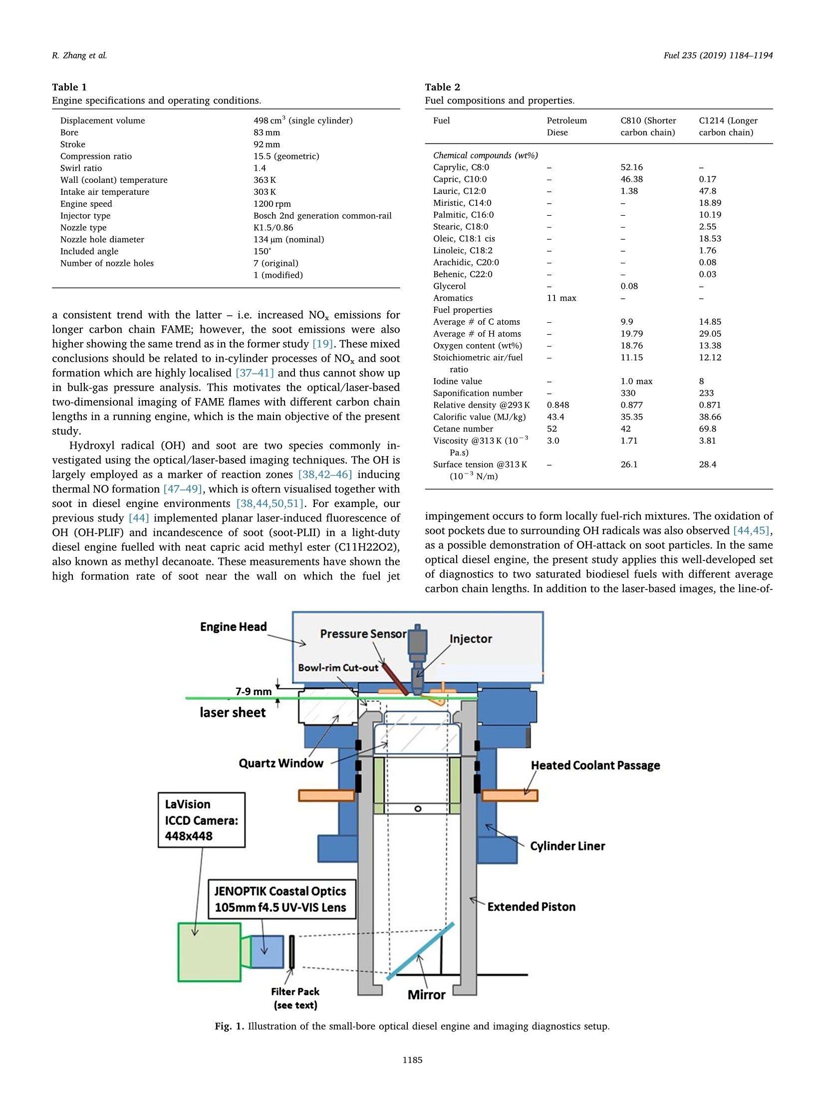
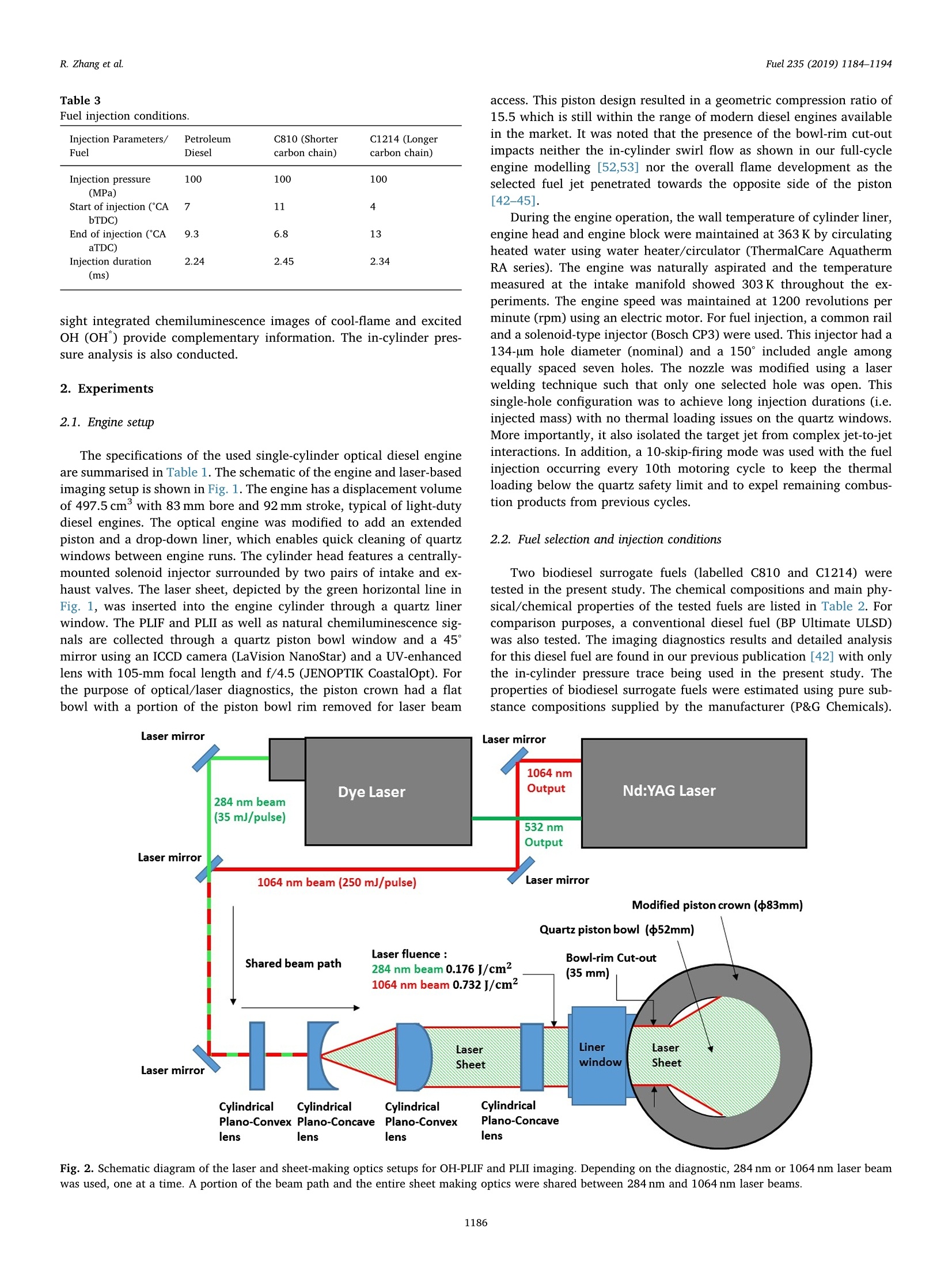
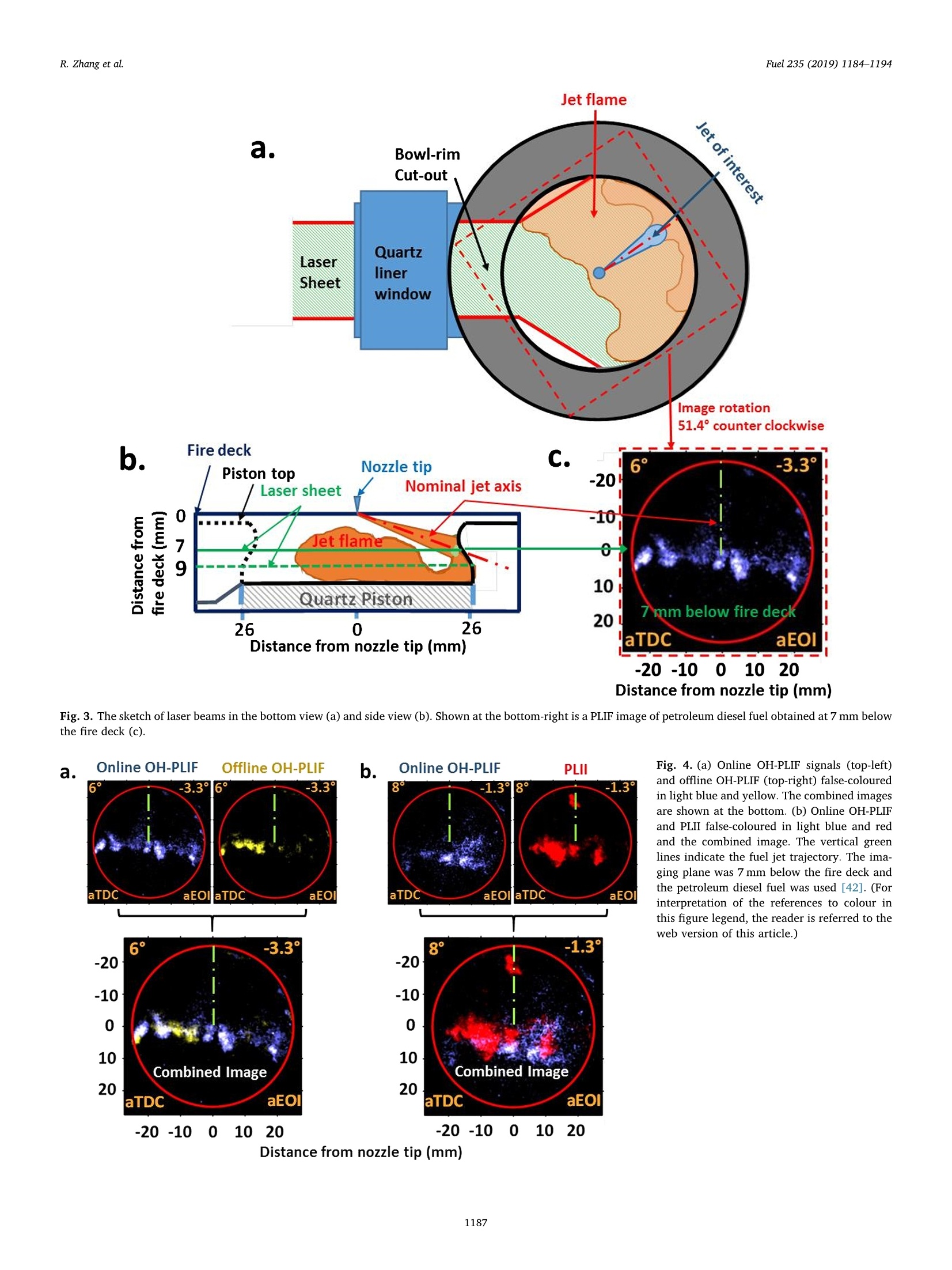
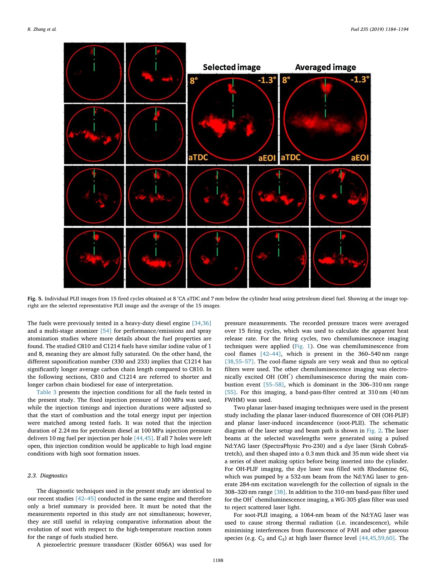
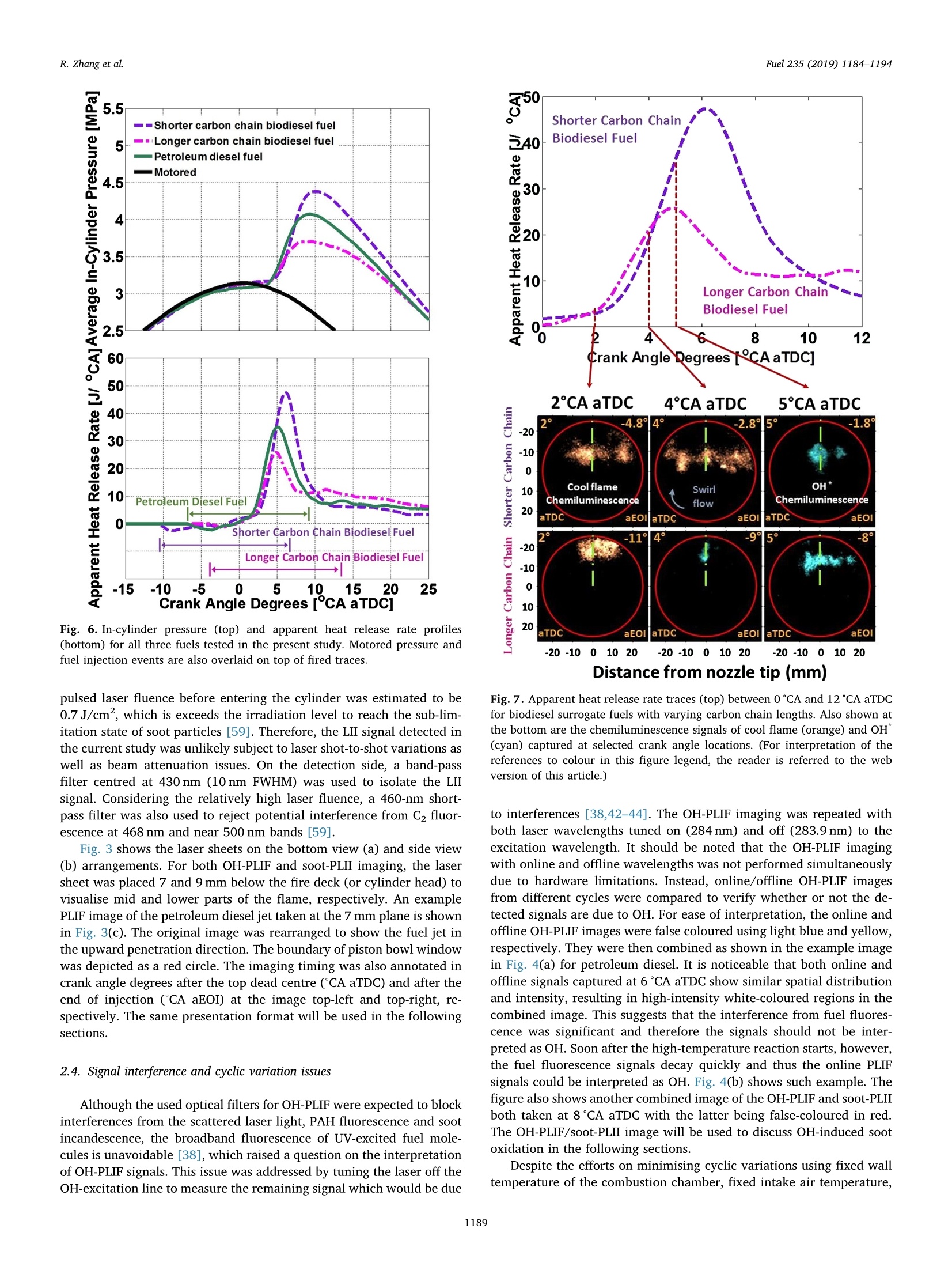
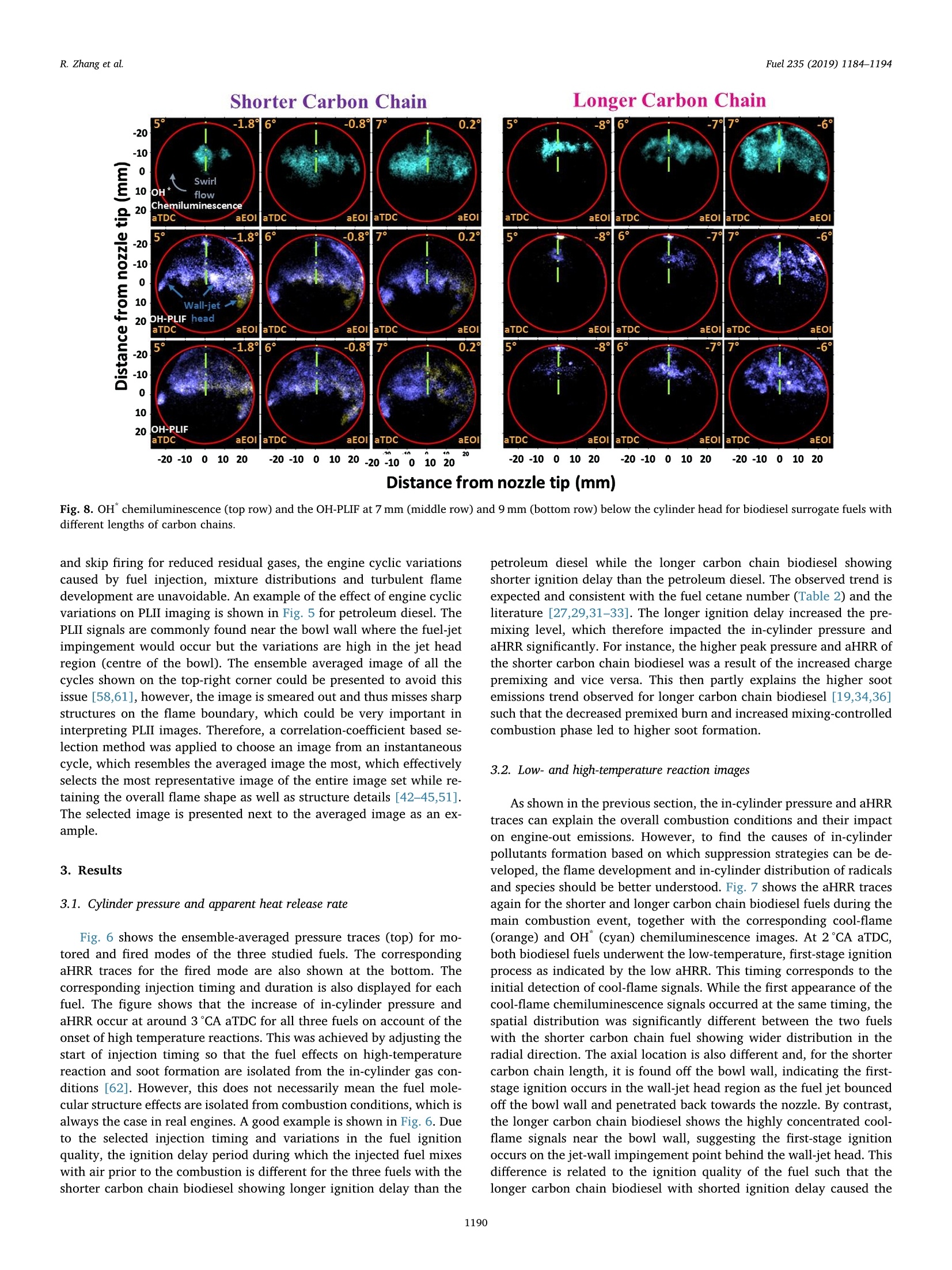
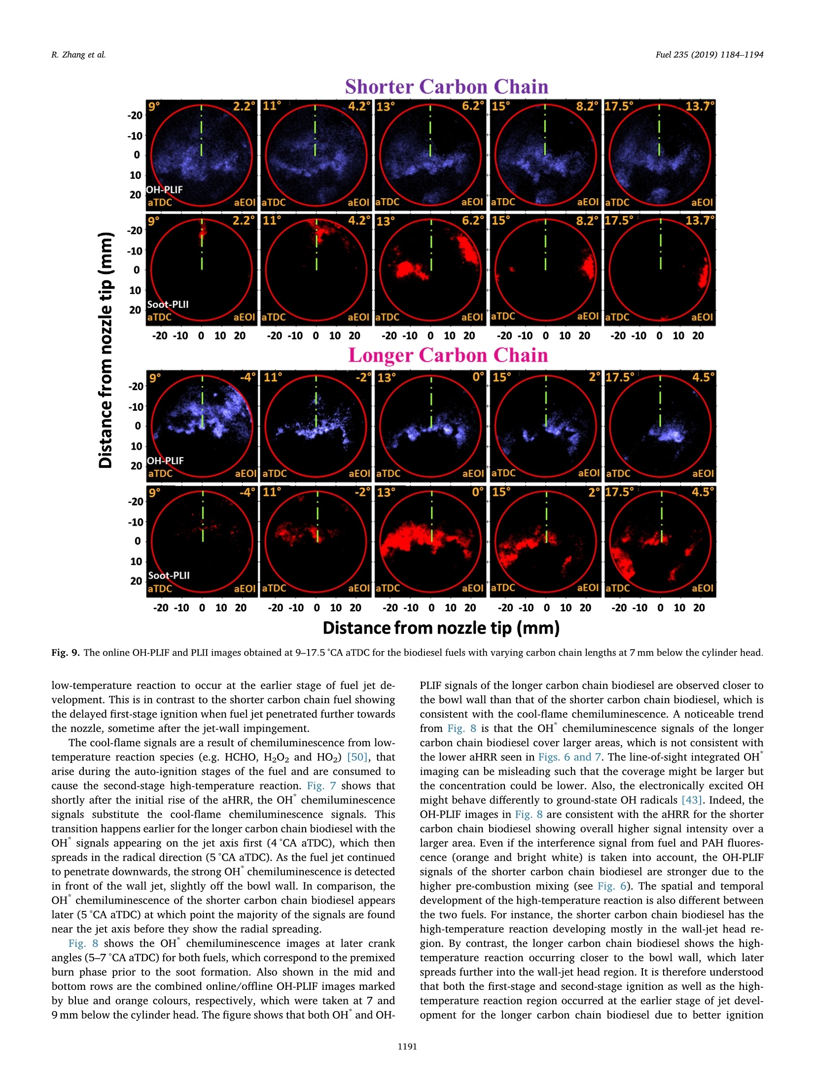
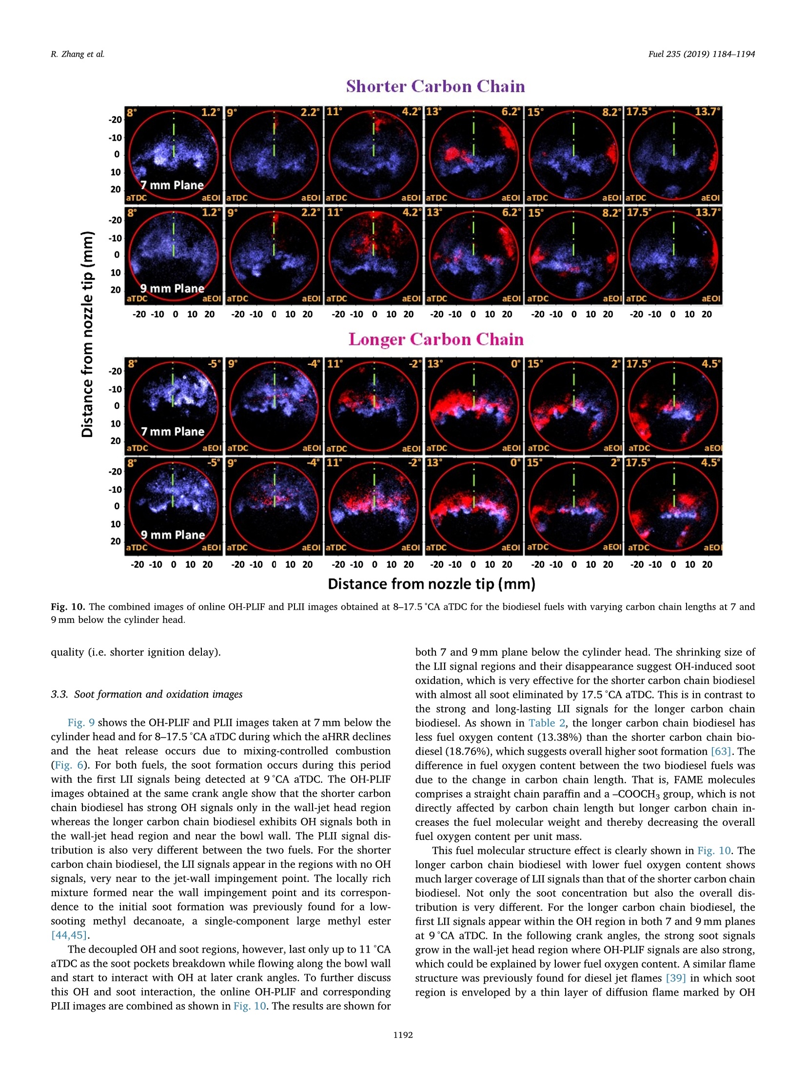
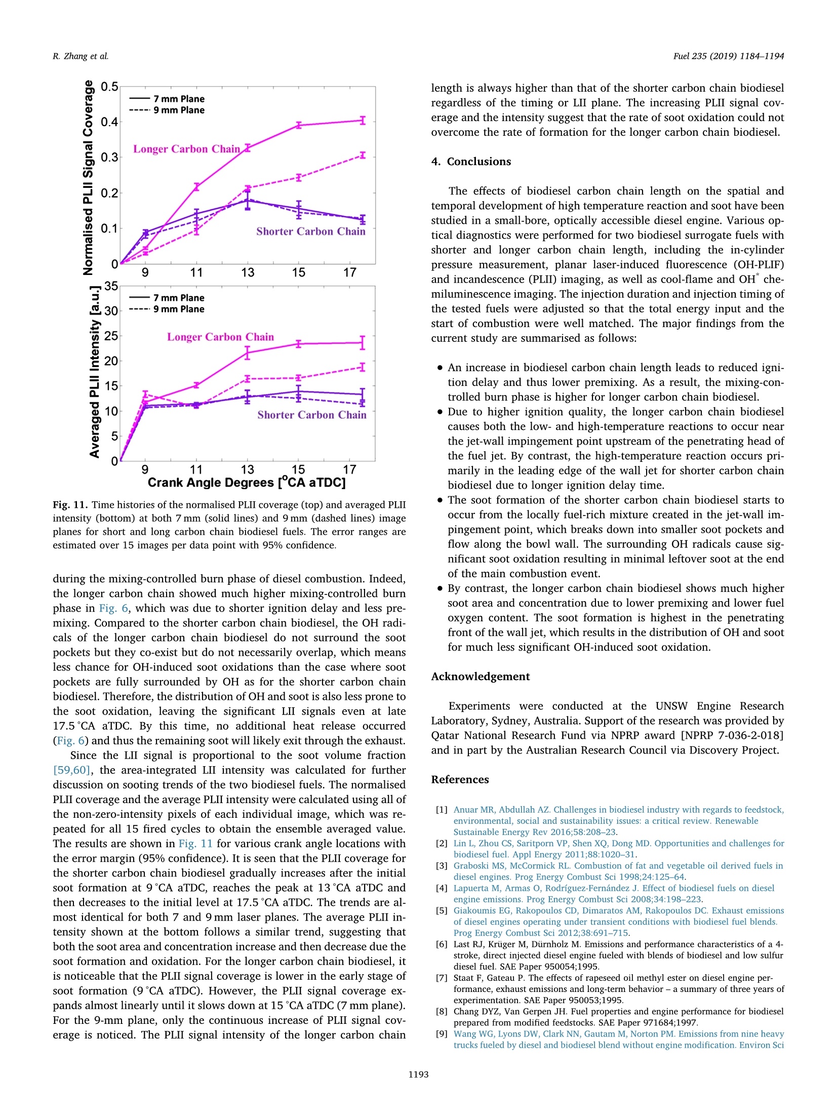
Fuel 235 (2019) 1184-1194Contents lists available at ScienceDirectjournal homepage: www.elsevier.com/locate/fuel R. Zhang et al.Fuel 235 (2019)1184-1194 Fuel Full Length Article Influence of biodiesel carbon chain length on in-cylinder soot processes in asmall bore optical diesel engine Renlin Zhang , Phuong X. Pham, Sanghoon Kook ,*, Assaad R. Masri School of Mechanical and Manufacturing Engineering, The University of New South Wales, Sydney, NSW 2052, AustraliaSchool of Aerospace, Mechanical and Mechatronic Engineering, The University of Sydney, NSW 2006, Australia A RTICLEINFO ABSTRA C T Keywords:Diesel engineBiodieselCarbon chain lengthOH Soot This study examines the effects of biodiesel carbon chain length on the development of high-temperature flameand soot in single-cylinder, light-duty, optical diesel engine. Planar laser-induced fluorescence of OH (OH-PLIF)and laser-induced incandescence (soot-PLII) are performed separately using petroleum diesel and two biodieselsurrogate fuels. The selected surrogate fuels have a saponification number (SN) of 330 and 233 for shorter andlonger carbon chain length, respectively, while the iodine value (IV) characterising the degree of unsaturation iskept similar. The laser-based images are shown together with the chemiluminescence images of naturally oc-curring cool-flame signals and electronically excited OH (OH"). The start of high-temperature reaction timingwas matched for the tested fuels by adjusting the injection timing so that the in-cylinder ambient conditions atthe start of combustion were consistent. The results show that the longer carbon chain biodiesel has shorterignition delay time, which makes a significant impact on the spatial and temporal development of high-tem-perature reaction zones. The OH signals for the longer carbon chain length biodiesel are observed close to thepiston-bowl wall whereas they appear later in the penetrating front of the wall-interacting jet for the shortercarbon chain length biodiesel. Both fuels show soot formation occurring in the wall jet head region while thelonger carbon chain length biodiesel has higher soot concentration and larger area than that of the shortercarbon chain biodiesel. This is due to lower pre-combustion mixing, reduced fuel oxygen content, and possiblyless significant OH-induced soot oxidation. 1. Introduction Recent studies suggest the market share of biodiesel fuels are ex-pected to increase to 5-10% of the overall diesel fuel supply in manycountries [1,2]. The primary aims are the diversification of fuel supplychains and potential carbon neutral benefits; however, the reducedengine-out emissions such as unburned hydrocarbons (uHC), carbonmonoxide (CO) and particulate matters (PM) are additional advantages[3-5]. The reduced emissions are due to the oxygen content in biodieseland the absence of aromatic hydrocarbons, which limits the formationof the pollutants and promotes oxidation [6-20]. However, the level ofemissions reduction varies significantly with the molecular structure ofthe fuel. When methanol is used in the transesterification process[21-24], biodiesel is referred to as a mixture of fatty acid methyl esters(FAME) with its composition varying with the feedstock [24-27]. Forexample, palm-oil biodiesel commonly comprises over 40% palmiticacid methyl ester (C17H3402) while a much smaller proposition(<10%) is found iin rapeseed-oil biodiesel[24]. The molecular structure of these FAMEs directly impacts physical and chemicalproperties of biodiesel [24,27-30], which in turn affects the engine-outemissions level [19,31-34]. One of the most defining structural features of FAME is the length ofcarbon chain (i.e. the number of C atoms). The carbon atoms in thesaturated alkyl chain of FAMEs are connected by carbon-to-carbonbonds, forming a straight chain structure, which determines the cetanenumber, heating value and viscosity [27-30,33,35]. The result is sig-nificantly different combustion and emission levels. For instance, onestudy [19] reported that increasing carbon chain length of individualFAME decreases its ignition delay time and thus the ratio of premixed tomixing-controlled burn, causing lower temperature and thus reducedNOx and increased soot emissions. However, another study [32]showed higher NOx emission for longer carbon chain FAME as the ig-nition delay and thus charge premixing level was fixed - it was ex-plained that the higher adiabatic flame temperature for longer carbonchain FAME was responsible for promoting thermal NO formation. Ourprevious work conducted in a heavy-duty diesel engine [34,36] showed ( E-mail address: s .ko o k@ un sw. e du . au ( S. K ook). ) ( ht t p s :// doi.o rg/ 1 0 . 1016/j. f uel.2 0 18.08.09 6 ) ( 0016-2361/C 2 018 Elsevier Ltd. All rights r eserved. ) Engine specifications and operating conditions. Displacement volume 498 cm(single cylinder) C810 (Shorter C1214 (Longer Bore 83 mm carbon chain) carbon chain) Stroke 92mm Compression ratio 15.5 (geometric) 52.16 Swirl ratio 1.4 46.38 0.17 Wall (coolant) temperature 363 K 1.38 47.8 Intake air temperature 303K 18.89 Engine speed 1200 rpm 10.19 Injector type Bosch 2nd generation common-rail 2.55 Nozzle type K1.5/0.86 18.53 Nozzle hole diameter 134 um (nominal) 1.76 Included angle 150° 0.08 Number of nozzle holes 7 (original) 0.03 Glycerol Aromatics 1 (modified) 0.08 Fuel properties Average # of Catoms 9.9 14.85 Average # of H atoms 19.79 29.05 Oxygen content (wt%) 18.76 13.38 Stoichiometric air/fuel 11.15 12.12 ratio Iodine value 1.0 max 8 Saponification number 330 233 Relative density @293 K 0.848 0.877 0.871 Calorific value (MJ/kg) 43.4 35.35 38.66 Cetane number 52 42 69.8 Viscosity @313 K (10 3.0 1.71 3.81 Pa.s) Surface tension @313 K (10-°N/m) 26.1 28.4 vestigated using the optical/laser-based imaging techniques. The OH islargely employed as a marker of reaction zones [38,42-46] inducingthermal NO formation [47-49], which is oftern visualised together withsoot in diesel engine environments [38,44,50,51]. For example, ourprevious study [44] implemented planar laser-induced fluorescence ofOH (OH-PLIF) and incandescence of soot (soot-PLII) in a light-dutydiesel engine fuelled with neat capric acid methyl ester (C11H22O2),also known as methyl decanoate. These measurements have shown thehigh formation rate of soot near the wall on which the fuel jet Table 2Fuel compositions and properties. (10-°N/m) impingement occurs to form locally fuel-rich mixtures. The oxidation ofsoot pockets due to surrounding OH radicals was also observed [44,45],as a possible demonstration of OH-attack on soot particles. In the sameoptical diesel engine, the present study applies this well-developed setof diagnostics to two saturated biodiesel fuels with different averagecarbon chain lengths. In addition to the laser-based images, the line-of- Fig. 1. Illustration of the small-bore optical diesel engine and imaging diagnostics setup. Table 3Fuel injection conditions. Injection Parameters/ Petroleum C810 (Shorter C1214 (Longer Fuel Diesel carbon chain) carbon chain) Injection pressure 100 100 100 (MPa) Start of injection (CA 7 11 4 bTDC) End of injection (CA 9.3 6.8 13 aTDC) Injection duration 2.24 2.45 2.34 (ms) sight integrated chemiluminescence images of cool-flame and excitedoH (OH*) provide complementary information. The in-cylinder pres-sure analysis is also conducted. 2. Experiments 2.1. Engine setup The specifications of the used single-cylinder optical diesel engineare summarised in Table 1. The schematic of the engine and laser-basedimaging setup is shown in Fig. 1. The engine has a displacement volumeof 497.5 cm’ with 83 mm bore and 92 mm stroke, typical of light-dutydiesel engines. The optical engine was modified to add an extendedpiston and a drop-down liner, which enables quick cleaning of quartzwindows between engine runs. The cylinder head features a centrally-mounted solenoid injector surrounded by two pairs of intake and ex-haust valves. The laser sheet, depicted by the green horizontal line inFig. 1, was inserted into the engine cylinder through a quartz linerwindow. The PLIF and PLII as well as natural chemiluminescence sig-nals are collected through a quartz piston bowl window and a 45°mirror using an ICCD camera (LaVision NanoStar) and a UV-enhancedlens with 105-mm focal length and f/4.5 (JENOPTIK CoastalOpt). Forthe purpose of optical/laser diagnostics, the piston crown had a flatbowl with a portion of the piston bowl rim removed for laser beam access. This piston design resulted in a geometric compression ratio of15.5 which is still within the range of modern diesel engines availablein the market. It was noted that the presence of the bowl-rim cut-outimpacts neither the in-cylinder swirl flow as shown in our full-cycleengine modelling [52,53] nor the overall flame development as theselected fuel jet penetrated towards the opposite side of the piston[42-451. During the engine operation, the wall temperature of cylinder liner,engine head and engine block were maintained at 363 K by circulatingheated water using water heater/circulator (ThermalCare AquathermRA series). The engine was naturally aspirated and the temperaturemeasured at the intake manifold showed 303K throughout the ex-periments. The engine speed was maintained at 1200 revolutions perminute (rpm) using an electric motor. For fuel injection, a common railand a solenoid-type injector (Bosch CP3) were used. This injector had a134-um hole diameter (nominal) and a 150°included angle amongequally spaced seven holes. The nozzle was modified using a laserwelding technique such that only one selected hole was open. Thissingle-hole configuration was to achieve long injection durations (i.e.injected mass) with no thermal loading issues on the quartz windows.More importantly, it also isolated the target jet from complex jet-to-jetinteractions. In addition, a 10-skip-firing mode was used with the fuelinjection occurring every 10th motoring cycle to keep the thermalloading below the quartz safety limit and to expel remaining combus-tion products from previous cycles. 2.2. Fuel selection and injection conditions Two biodiesel surrogate fuels (labelled C810 and C1214) weretested in the present study. The chemical compositions and main phy-sical/chemical properties of the tested fuels are listed in Table 2. Forcomparison purposes, a conventional diesel fuel (BP Ultimate ULSD)was also tested. The imaging diagnostics results and detailed analysisfor this diesel fuel are found in our previous publication [42] with onlythe in-cylinder pressure trace being used in the present study. Theproperties of biodiesel surrogate fuels were estimated using pure sub-stance compositions supplied by the manufacturer (P&G Chemicals). Fig. 2. Schematic diagram of the laser and sheet-making optics setups for OH-PLIF and PLII imaging. Depending on the diagnostic, 284 nm or 1064 nm laser beamwas used, one at a time. A portion of the beam path and the entire sheet making optics were shared between 284 nm and 1064 nm laser beams. Image rotation 51.4°counter clockwise C. Fig. 3. The sketch of laser beams in the bottom view (a) and side view (b). Shown at the bottom-right is a PLIF image of petroleum diesel fuel obtained at 7 mm belowthe fire deck (c). a. Fig. 4. (a) Online OH-PLIF signals (top-left)and offline OH-PLIF (top-right) false-colouredin light blue and yellow. The combined imagesare shown at the bottom. (b) Online OH-PLIFand PLII false-coloured in light blue and redand the combined image. The vertical greenlines indicate the fuel jet trajectory. The ima-ging plane was 7 mm below the fire deck andthe petroleum diesel fuel was used [42]. (Forinterpretation of the references to colour inthis figure legend, the reader is referred to theweb version of this article.) Distance from nozzle tip (mm) Fig. 5. Individual PLII images from 15 fired cycles obtained at 8℃A aTDC and 7 mm below the cylinder head using petroleum diesel fuel. Showing at the image top-right are the selected representative PLII image and the average of the 15 images. The fuels were previously tested in a heavy-duty diesel engine [34,36]and a multi-stage atomizer [54] for performance/emissions and sprayatomization studies where more details about the fuel properties arefound. The studied C810 and C1214 fuels have similar iodine value of 1and 8, meaning they are almost fully saturated.On the other hand, thedifferent saponification number (330 and 233) implies that C1214 hassignificantly longer average carbon chain length compared to C810. Inthe following sections, C810 and C1214 are referred to shorter andlonger carbon chain biodiesel for ease of interpretation. Table 3 presents the injection conditions for all the fuels tested inthe present study. The fixed injection pressure of 100 MPa was used,while the injection timings and injection durations were adjusted sothat the start of combustion and the total energy input per injectionwere matched among tested fuels. It was noted that the injectionduration of 2.24 ms for petroleum diesel at 100 MPa injection pressuredelivers 10 mg fuel per injection per hole [44,45]. If all 7 holes were leftopen, this injection condition would be applicable to high load engineconditions with high soot formation issues. 2.3. Diagnostics The diagnostic techniques used in the present study are identical toour recent studies [42-45] conducted in the same engine and thereforeonly a brief summary is provided here. It must be noted that themeasurements reported in this study are not simultaneous; however,they are still useful in relaying comparative information about theevolution of soot with respect to the high-temperature reaction zonesfor the range of fuels studied here. A piezoelectric pressure transducer (Kistler 6056A) was used for pressure measurements. The recorded pressure traces were averagedover 15 firing cycles, which was used to calculate the apparent heatrelease rate. For the firing cycles, two chemiluminescnece imagingtechniques were applied (Fig. 1). One was chemiluminescence fromcool flames [42-44], which is present in the 360-540nm range[38,55-57]. The cool-flame signals are very weak and thus no opticalfilters were used. The other chemiluminescence imaging was electro-nically excited OH (OH) chemiluminescence during the main com-bustion event [55-58], which is dominant in the 306-310 nm range[55]. For this imaging, a band-pass-filter centred at 310 nm (40 nmFWHM) was used. Two planar laser-based imaging techniques were used in the presentstudy including the planar laser-induced fluorescence of OH (OH-PLIF)and planar laser-induced incandescence (soot-PLII). The schematicdiagram of the laser setup and beam path is shown in Fig. 2. The laserbeams at the selected wavelengths were generated using a pulsedNd:YAG laser (SpectraPhysic Pro-230) and a dye laser (Sirah CobraS-tretch), and then shaped into a 0.3 mm thick and 35 mm wide sheet viaa series of sheet making optics before being inserted into the cylinder.For OH-PLIF imaging, the dye laser was filled with Rhodamine 6G,which was pumped by a 532-nm beam from the Nd:YAG laser to gen-erate 284-nm excitation wavelength for the collection of signals in the308-320 nm range [38]. In addition to the 310-nm band-pass filter usedfor the OH chemiluminescence imaging, a WG-305 glass filter was usedto reject scattered laser light. For soot-PLII imaging, a 1064-nm beam of the Nd:YAG laser wasused to cause strong thermal radiation (i.e. incandescence), whileminimising interferences from fluorescence of PAH and other gaseousspecies (e.g. C2 and C3) at high laser fluence level [44,45,59,60]. The Fig. 6. In-cylinder pressure (top) and apparent heat release rate profiles(bottom) for all three fuels tested in the present study. Motored pressure andfuel injection events are also overlaid on top of fired traces. pulsed laser fluence before entering the cylinder was estimated to be0.7 J/cm, which is exceeds the irradiation level to reach the sub-lim-itation state of soot particles [59]. Therefore, the LII signal detected inthe current study was unlikely subject to laser shot-to-shot variations aswell as beam attenuation issues. On the detection side, a band-passfilter centred at 430 nm (10 nm FWHM) was used to isolate the LIIsignal. Considering the relatively high laser fluence, a 460-nm short-pass filter was also used to reject potential interference from C2 fluor-escence at 468 nm and near 500 nm bands [59]. Fig. 3 shows the laser sheets on the bottom view (a) and side view(b) arrangements. For both OH-PLIF and soot-PLII imaging, the lasersheet was placed 7 and 9 mm below the fire deck (or cylinder head) tovisualise mid and lower parts of the flame, respectively. An examplePLIF image of the petroleum diesel jet taken at the 7 mm plane is shownin Fig. 3(c). The original image was rearranged to show the fuel jet inthe upward penetration direction. The boundary of piston bowl windowwas depicted as a red circle. The imaging timing was also annotated incrank angle degrees after the top dead centre (CA aTDC) and after theend of injection (CA aEOI) at the image top-left and top-right, re-spectively. The same presentation format will be used in the followingsections. 2.4. Signal interference and cyclic variation issues Although the used optical filters for OH-PLIF were expected to blockinterferences from the scattered laser light, PAH fluorescence and sootincandescence, the broadband fluorescence of UV-excited fuel mole-cules is unavoidable [38], which raised a question on the interpretationof OH-PLIF signals. This issue was addressed by tuning the laser off theOH-excitation line to measure the remaining signal which would be due Fig. 7. Apparent heat release ratetraces (top) between 0°CA and 12°CA aTDCfor biodiesel surrogate fuels with varying carbon chain lengths. Also shown atthe bottom are the chemiluminescence signals of cool flame (orange) and OH(cyan) captured at selected crank angle locations. (For interpretation of thereferences to colour in this figure legend, the reader is referred to the webversion of this article.) to interferences [38,42-44]. The OH-PLIF imaging was repeated withboth laser wavelengths tuned on (284 nm) and off (283.9nm) to theexcitation wavelength. It should be noted that the OH-PLIF imagingwith online and offline wavelengths was not performed simultaneouslydue to hardware limitations. Instead, online/offline OH-PLIF imagesfrom different cycles were compared to verify whether or not the de-tected signals are due to OH. For ease of interpretation, the online andoffline OH-PLIF images were false coloured using light blue and yellow,respectively. They were then combined as shown in the example imagein Fig. 4(a) for petroleum diesel. It is noticeable that both online andoffline signals captured at 6°CA aTDC show similar spatial distributionand intensity, resulting in high-intensity white-coloured regions in thecombined image. This suggests that the interference from fuel fluores-cence was significant and therefore the signals should not be inter-preted as OH. Soon after the high-temperature reaction starts, however,the fuel fluorescence signals decay quickly and thus the online PLIFsignals could be interpreted as OH. Fig. 4(b) shows such example. Thefigure also shows another combined image of the OH-PLIF and soot-PLIIboth taken at 8CA aTDC with the latter being false-coloured in red.The OH-PLIF/soot-PLII image will be used to discuss OH-induced sootoxidation in the following sections. Despite the efforts on minimising cyclic variations using fixed walltemperature of the combustion chamber, fixed intake air temperature, Shorter Carbon Chain Longer Carbon Chain Distance from nozzle tip (mm) Fig.8. OH chemiluminescence (top row) and the OH-PLIF at 7 mm (middle row) and 9 mm (bottom row) below the cylinder head for biodiesel surrogate fuels withdifferent lengths of carbon chains. and skip firing for reduced residual gases, the engine cyclic variationscaused by fuel injection, mixture distributions and turbulent flamedevelopment are unavoidable. An example of the effect of engine cyclicvariations on PLII imaging is shown in Fig. 5 for petroleum diesel. ThePLII signals are commonly found near the bow wall where the fuel-jetimpingement would occur but the variations are high in the jet headregion (centre of the bowl). The ensemble averaged image of all thecycles shown on the top-right corner could be presented to avoid thisissue [58,61], however, the image is smeared out and thus misses sharpstructures on the flame boundary, which could be very important ininterpreting PLII images. Therefore, a correlation-coefficient based se-lection method was applied to choose an image from an instantaneouscycle, which resembles the averaged image the most, which effectivelyselects the most representative image of the entire image set while re-taining the overall flame shape as well as structure details [42-45,51].The selected image is presented next to the averaged image as an ex-ample. 3. Results 3.1. Cylinder pressure and apparent heat release rate Fig. 6 shows the ensemble-averaged pressure traces (top) for mo-tored and fired modes of the three studied fuels. The correspondingaHRR traces for the fired mode are also shown at the bottom. Thecorresponding injection timing and duration is also displayed for eachfuel. The figure shows that the increase of in-cylinder pressure andaHRR occur at around 3°CA aTDC for all three fuels on account of theonset of high temperature reactions. This was achieved by adjusting thestart of injection timing so that the fuel effects on high-temperaturereaction and soot formation are isolated from the in-cylinder gas con-ditions [62]. However, this does not necessarily mean the fuel mole-cular structure effects are isolated from combustion conditions, which isalways the case in real engines. A good example is shown in Fig. 6. Dueto the selected injection timing and variations in the fuel ignitionquality, the ignition delay period during which the injected fuel mixeswith air prior to the combustion is different for the three fuels with theshorter carbon chain biodiesel showing longer ignition delay than the petroleum diesel while the longer carbon chain biodiesel showingshorter ignition delay than the petroleum diesel. The observed trend isexpected and consistent with the fuel cetane number (Table 2) and theliterature [27,29,31-33]. The longer ignition delay increased the pre-mixing level, which therefore impacted the in-cylinder pressure andaHRR significantly. For instance, the higher peak pressure and aHRR ofthe shorter carbon chain biodiesel was a result of the increased chargepremixing and vice versa. This then partly explains the higher sootemissions trend observed for longer carbon chain biodiesel [19,34,36]such that the decreased premixed burn and increased mixing-controlledcombustion phase led to higher soot formation. 3.2. Low- and high-temperature reaction images As shown in the previous section, the in-cylinder pressure and aHRRtraces can explain the overall combustion conditions and their impact1ons:on engine-out emissions. However, to find the causes of in-cylinderpollutants formation based on which suppression strategies can be de-veloped, the flame development and in-cylinder distribution of radicalsand species should be better understood. Fig.7 shows the aHRR tracesagain for the shorter and longer carbon chain biodiesel fuels during themain combustion event, together with the corresponding cool-flame(orange) and OH"(cyan) chemiluminescence images. At 2℃A aTDC,both biodiesel fuels underwent the low-temperature, first-stage ignitionprocess as indicated by the low aHRR. This timing corresponds to theinitial detection of cool-flame signals. While the first appearance of thecool-flame chemiluminescence signals occurred at the same timing, thespatial distribution was significantly different between the two fuelswith the shorter carbon chain fuel showing wider distribution in theradial direction. The axial location is also different and, for the shortercarbon chain length, it is found off the bowl wall, indicating the first-stage ignition occurs in the wall-jet head region as the fuel jet bouncedoff the bowl wall and penetrated back towards the nozzle. By contrast,the longer carbon chain biodiesel shows the highly concentrated cool-flame signals near the bowl wall, suggesting the first-stage ignitionoccurs on the jet-wall impingement point behind the wall-jet head. Thisdifference is related to the ignition quality of the fuel such that thelonger carbon chain biodiesel with shorted ignition delay caused the Shorter Carbon Chain Distance from nozzle tip (mm) low-temperature reaction to occur at the earlier stage of fuel jet de-velopment. This is in contrast to the shorter carbon chain fuel showingthe delayed first-stage ignition when fuel jet penetrated further towardsthe nozzle, sometime after the jet-wall impingement. The cool-flame signals are a result of chemiluminescence from low-temperature reaction species (e.g. HCHO, H202 and HO2) [50], thatarise during the auto-ignition stages of the fuel and are consumed tocause the second-stage high-temperature reaction. Fig.7 shows thatshortly after the initial rise of the aHRR, the OH"chemiluminescencesignals substitute the cool-flame chemiluminescence signals. Thistransition happens earlier for the longer carbon chain biodiesel with theOH*signals appearing on the jet axis first (4℃A aTDC), which thenspreads in the radical direction (5°CA aTDC). As the fuel jet continuedto penetrate downwards, the strong OH" chemiluminescence is detectedin front of the wall jet, slightly off the bowl wall. In comparison, theOH* chemiluminescence of the shorter carbon chain biodiesel appearslater (5°CA aTDC) at which point the majority of the signals are foundnear the jet axis before they show the radial spreading. Fig. 8 shows the OH chemiluminescence images at later crankangles (5-7CA aTDC) for both fuels, which correspond to the premixedburn phase prior to the soot formation. Also shown in the mid andbottom rows are the combined online/offline OH-PLIF images markedby blue and orange colours, respectively, which were taken at 7 and9 mm below the cylinder head. The figure shows that both OHand OH- PLIF signals of the longer carbon chain biodiesel are observed closer tothe bowl wall than that of the shorter carbon chain biodiesel, which isconsistent with the cool-flame chemiluminescence. A noticeable trendfrom Fig. 8 is that the OH* chemiluminescence signals of the longercarbon chain biodiesel cover larger areas, which is not consistent withthe lower aHRR seen in Figs. 6 and 7. The line-of-sight integrated OH"imaging can be misleading such that the coverage might be larger butthe concentration could be lower. Also, the electronically excited OHmight behave differently to ground-state OH radicals [43]. Indeed, theOH-PLIF images in Fig. 8 are consistent with the aHRR for the shortercarbon chain biodiesel showing overall higher signal intensity over alarger area. Even if the interference signal from fuel and PAH fluores-cence (orange and bright white) is taken into account, the OH-PLIFsignals of the shorter carbon chain biodiesel are stronger due to thehigher pre-combustion mixing (see Fig. 6). The spatial and temporaldevelopment of the high-temperature reaction is also different betweenthe two fuels. For instance, the shorter carbon chain biodiesel has thehigh-temperature reaction developing mostly in the wall-jet head re-gion. By contrast, the longer carbon chain biodiesel shows the high-temperature reaction occurring closer to the bowl wall, which laterspreads further into the wall-jet head region. It is therefore understoodthat both the first-stage and second-stage ignition as well as the high-temperature reaction region occurred at the earlier stage of jet devel-opment for the longer carbon chain biodiesel due to better ignition 3.3. Soot formation and oxidation images Fig. 9 shows the OH-PLIF and PLII images taken at 7 mm below thecylinder head and for 8-17.5 °℃A aTDC during which the aHRR declinesand the heat release occurs due to mixing-controlled combustion(Fig. 6). For both fuels, the soot formation occurs during this periodwith the first LII signals being detected at 9℃A aTDC. The OH-PLIFimages obtained at the same crank angle show that the shorter carbonchain biodiesel has strong OH signals only in the wall-jet head regionwhereas the longer carbon chain biodiesel exhibits OH signals both inthe wall-jet head region and near the bowl wall. The PLII signal dis-tribution is also very different between the two fuels. For the shortercarbon chain biodiesel, the LII signals appear in the regions with no OHsignals, very near to the jet-wall impingement point. The locally richmixture formed near the wall impingement point and its correspon-dence to the initial soot formation was previously found for a low-sooting methyl decanoate, a single-component large methyl ester[44,45]. The decoupled OH and soot regions, however, last only up to 11CAaTDC as the soot pockets breakdown while flowing along the bowl walland start to interact with OH at later crank angles. To further discussthis OH and soot interaction, the online OH-PLIF and correspondingPLII images are combined as shown in Fig. 10. The results are shown for both 7 and 9mm plane below the cylinder head. The shrinking size ofthe LII signal regions and their disappearance suggest OH-induced sootoxidation, which is very effective for the shorter carbon chain biodieselwith almost all soot eliminated by 17.5CA aTDC. This is in contrast tothe strong and long-lasting LII signals for the longer carbon chainbiodiesel. As shown in Table 2, the longer carbon chain biodiesel hasless fuel oxygen content (13.38%) than the shorter carbon chain bio-diesel (18.76%), which suggests overall higher soot formation [63]. Thedifference in fuel oxygen content between the two biodiesel fuels wasdue to the change in carbon chain length. That is, FAME moleculescomprises a straight chain paraffin and a-COOCH3 group, which is notdirectly affected by carbon chain length but longer carbon chain in-creases the fuel molecular weight and thereby decreasing the overallfuel oxygen content per unit mass. This fuel molecular structure effect is clearly shown in Fig. 10. Thelonger carbon chain biodiesel with lower fuel oxygen content showsmuch larger coverage of LII signals than that of the shorter carbon chainbiodiesel. Not only the soot concentration but also the overall dis-tribution is very different. For the longer carbon chain biodiesel, thefirst LII signals appear within the OH region in both 7 and 9 mm planesat 9°CA aTDC. In the following crank angles, the strong soot signalsgrow in the wall-jet head region where OH-PLIF signals are also strong,which could be explained by lower fuel oxygen content. A similar flamestructure was previously found for diesel jet flames [39] in which sootregion is enveloped by a thin layer of diffusion flame marked by OH Fig.11. Time histories of the normalised PLII coverage (top) and averaged PLIIintensity (bottom) at both 7 mm (solid lines) and 9 mm (dashed lines) imageplanes for short and long carbon chain biodiesel fuels. The error ranges areestimated over 15 images per data point with 95% confidence. during the mixing-controlled burn phase of diesel combustion.Indeed,the longer carbon chain showed much higher mixing-controlled burnphase in Fig. 6, which was due to shorter ignition delay and less pre-mixing. Compared to the shorter carbon chain biodiesel, the OH radi-cals of the longer carbon chain biodiesel do not surround the sootpockets but they co-exist but do not necessarily overlap, which meansless chance for OH-induced soot oxidations than the case where sootpockets are fully surrounded by OH as for the shorter carbon chainbiodiesel. Therefore, the distribution of OH and soot is also less prone tothe soot oxidation, leaving the significant LII signals even at late17.5°℃A aTDC. By this time, no additional heat release occurred(Fig.6) and thus the remaining soot will likely exit through the exhaust. Since the LII signal is proportional to the soot volume fraction[59,60], the area-integrated LII intensity was calculated for furtherdiscussion on sooting trends of the two biodiesel fuels. The normalisedPLII coverage and the average PLII intensity were calculated using all ofthe non-zero-intensity pixels of each individual image, which was re-peated for all 15 fired cycles to obtain the ensemble averaged value.The results are shown in Fig. 11 for various crank angle locations withthe error margin (95% confidence). It is seen that the PLII coverage forthe shorter carbon chain biodiesel gradually increases after the initialsoot formation at 9CA aTDC, reaches the peak at 13℃A aTDC andthen decreases to the initial level at 17.5°CA aTDC. The trends are al-most identical for both 7 and 9 mm laser planes. The average PLII in-tensity shown at the bottom follows a similar trend, suggesting thatboth the soot area and concentration increase and then decrease due thesoot formation and oxidation. For the longer carbon chain biodiesel, itis noticeable that the PLII signal coverage is lower in the early stage ofsoot formation (9°CA aTDC). However, the PLII signal coverage ex-pands almost linearly until it slows down at 15CA aTDC (7mm plane).For the 9-mm plane, only the continuous increase of PLII signal cov-erage is noticed. The PLII signal intensity of the longer carbon chain length is always higher than that of the shorter carbon chain biodieselregardless of the timing or LII plane. The increasing PLII signal cov-erage and the intensity suggest that the rate of soot oxidation could notovercome the rate of formation for the longer carbon chain biodiesel. 4. Conclusions The effects of biodiesel carbon chain length on the spatial andtemporal development of high temperature reaction and soot have beenstudied in a small-bore, optically accessible diesel engine. Various op-tical diagnostics were performed for two biodiesel surrogate fuels withshorter and longer carbon chain length, including the in-cylinderpressure measurement, planar laser-induced fluorescence (OH-PLIF)and incandescence (PLII) imaging, as well as cool-flame and OH*che-miluminescence imaging. The injection duration and injection timing ofthe tested fuels were adjusted so that the total energy input and thestart of combustion were well matched. The major findings from thecurrent study are summarised as follows: · An increase in biodiesel carbon chain length leads to reduced igni-tion delay and thus lower premixing. As a result, the mixing-con-trolled burn phase is higher for longer carbon chain biodiesel. ·Due to higher ignition quality, the longer carbon chain biodieselcauses both the low- and high-temperature reactions to occur nearthe jet-wall impingement point upstream of the penetrating head ofthe fuel jet. By contrast, the high-temperature reaction occurs pri-marily in the leading edge of the wall jet for shorter carbon chainbiodiesel due to longer ignition delay time. ● The soot formation of the shorter carbon chain biodiesel starts tooccur from the locally fuel-rich mixture created in the jet-wall im-pingement point, which breaks down into smaller soot pockets andflow along the bowl wall. The surrounding OH radicals cause sig-nificant soot oxidation resulting in minimal leftover soot at the endof the main combustion event. By contrast, the longer carbon chain biodiesel shows much highersoot area and concentration due to lower premixing and lower fueloxygen content. The soot formation is highest in the penetratingfront of the wall jet, which results in the distribution of OH and sootfor much less significant OH-induced soot oxidation. Acknowledgement Experiments were conducted at the UNSW Engine ResearchLaboratory, Sydney, Australia. Support of the research was provided byQatar National Research Fund via NPRP award [NPRP 7-036-2-018]and in part by the Australian Research Council via Discovery Project. ( References ) [1] Anuar MR, Abdullah AZ. Challenges in biodiesel industry with regards to feedstock,environmental, social and sustainability issues: a critical review. RenewableSustainable Energy Rev 2016;58:208-23. [2]Lin L, Zhou CS, Saritporn VP, Shen XQ, Dong MD. Opportunities and challenges forbiodiesel fuel. Appl Energy 2011;88:1020-31. ( [3] ( G ra b os k i MS, M c Co rmic k RL . Co m b u s ti o n of f a t a n d v e ge table o i l der ive d fu el s i n d i e s e l e n g ines . P rog En e rg y Co mb u st Sc i 1 9 9 8 ; 2 4: 1 25 -64. ) ( [4] ] L a p u erta M , A r m as O , Ro d ri g u e z-F er n an de z J. Ef f e ct o f b i o d ie se l fu e ls o n die s el e ng ine e m issions . Prog Ene rg y C ombust Sc i 2008 ; 34:19 8 - 2 2 3 . ) ( 0 1in [5] G i ak o u mi s EG, R a k o po ulos C D , D im a ra t os A M , R a k o p o ulos DC. E x h a u s t e m issio n s o f d i e se l e ngi n es o p e rat i n g un d er tra n s i en t c on d i t io ns wi th b iod i e se l fu el b l end s. P r og E ne r g y Com b ust Sci 2012; 3 8:691- 7 1 5 . ) ( [6] Last R J, K riger M, Duirnholz M. E m issions and pe r formance characteristics of a 4 -stroke, direct injected diesel engine fueled with b lends of biodiesel and low s u lfur diesel fuel. SAE Paper 950054;1995. ) [7] Staat F, Gateau P. The effects of rapeseed oil methyl ester on diesel engine per- ( L eD formance, exhaust e m issions and long-term behavior- a s u mmary of three year s ofexperimentation. SAE Paper 950053;1995. ) ( [8] Chang DYZ, Va n Gerpen JH. Fuel properties and engine performance for biodi e sel prepared from modified feedstocks. SAE Paper 971684;1997. ) [9]Wang WG, Lyons DW, Clark NN, Gautam M, Norton PM. Emissions from nine heavytrucks fueled by diesel and biodiesel blend without engine modification. Environ Sci ( T ec h nol 2000;34 : 933 - 9 . ) ( [10] D urbin T D , Norbe c k J M . Eff e ct s of b io d ie s e l b len d s a n d Ar c o EC-di es el o n emi s s i o ns f r o m l i g h t heav y - d uty d i e s e l veh ic l e s. E n vi r o n S ci T e c hnol 20 0 2 ; 36:1 6 8 6 - 91. ) ( [11] L apuerta M, Armas O, Ballesteros R. Diesel p articulate emissions from b iofuels ) ( d erived from S panish v egetable oils. SAE Paper 2002-01-1657;2002. ) ( [12] L e ung D Y C , L uo Y, Cha n TL. O p t imizati o n of ex h a u st emiss io ns of a d i e se l e n gine f uelled with b iodiesel. E nerg y F u e ls 2 006; 20 :1 0 15- 2 3 . ) ( [13 ] J o hanss on M , Y a n g JF , O c hote r ena R , Gj i rj a S , D enb r a t t I . N Ox an d s o ot e mis s i o n s t rends fo r RM E, SME a n d PM E f u els usi ng e ng in e a nd s p ra y e xp erime n t s i n c o m - b ina t io n wi t h simul a tions. Fuel 201 3 ; 1 06: 2 93- 30 2. ) ( [14] C a r d o n e M , P r at i MV, R o c c o V , Se g g ia n i M, Sen a t or e A, Vi tolo S. B ra ssi ca c a r i na t a a s a n a lternat i ve o i l cro p f o r th e p roductio n of bio d iesel i n I ta ly : en g i ne p e r f or- m ance a n d regu l at e d an d un r egulate d e x h aus t em i s s i ons. E n v i r o n S ci Te c h nol 2 002; 3 6: 4 656 - 6 2. ) ( [15] M o n ye m A , V a n Ge r p e n JH . T he e ff ec t of b i o d ie s el o x i d at io n on en g ine p erf or- m ance a nd e m i s s ion s. B i o m a s s Bio e ne rg y 2 0 01;2 0 :3 1 7-2 5 . ) ( [16] L iu X, Wang H , Y ao M. Experimental and modeling investigations on soot formation o f ethanol, n-butanol, 2,5-dimethylfuran, an d biodiesel in d iesel en g ines. Energy Fuels 2017. h ttps: //d oi.o r g/ 1 0. 1 021/ a cs .e n ergyf u e l s . 7 b 01622. ) ( [17] W oo C, K o o k S, Roge r s PL, M a rq u is C , H a wkes E R . A c o m parat i v e anal y sis on en- g i ne p erfo r m a n ce o f a c o nve n t i o n a l d i e se l f ue l an d 1 0 % b i od ie se l b lend s p rodu c e d f rom coconu t oils . SAE I n t J Fuel s Lubr 2015;8:5 9 7-609 . ) ( [18] W oo C, K o o k S , H awke s E R, R oger s P L , M a rq u is C . De p e n d e nc y of e n g i n e c o m- bus ti o n o n b le n din g ra t i o v a r i a tio n s o f l i p ase - c a ta l y se d c o c o n u t oil b i o d iesel a nd petroleum d iese l. F uel 201 6 ;1 6 9 : 146 - 57. ) ( [19] : Z hu L , C heung CS, H u ang Z. I m p a c t o f c hem i ca l s t r u c ture o f i ndividu a l f atty ac id e st e r s on c o mbu s tion and e m i s sion ch a r a c t er ist i cs o f di e sel en g in e. En e r g y 2 016; 1 0 7 : 3 05- 2 0. ) ( [20 ]J i ng W , W u Z Y , R oberts W L. F a n g T G S p ray c o m b u s tion o f b i oma ss - b a s e d renew- a bl e d ie se l fu e l u s i n g m ul t i p l e i n j ec ti o n str a t eg y i n a c ons t an t v o l u me c ombus t io n c hamber. F ue l 2 016 ;1 8 1 : 7 1 8 -28. ) ( [21] L a p u erta M , H errer o s J M , L yo n s LL, Gar cia- C o n trer a s R , B ri c eno Y . E ffect o f the a l c o h o l ty p e u s ed i n t he p r o d u ct i on o f w a s t e co okin g oil biodie s el o n d i e sel p er- f orma n ce an d em i s s i on s . F uel 2 0 08 ; 8 7 :3 16 1-9 . ) ( [22 ]S anl i H , C a na k ci M . E f fec ts of d i f ferent a lco ho l a nd c a ta l ys t usa g e on biodie s e l p ro d uc t i on fr o m d i ffer ent v e g e tab le o i ls . E n e r g y Fuels 2008; 2 2: 2 7 1 3- 9 . ) ( [23] H el l i e r P , L a dom m a to s N, A l l a n R , R o g e rso n J. T h e in f l u enc e o f f a t t y a ci d e s te r a l c o h o l m oie t y m olec u la r s t ructure o n die s el c o m bustion a n d e m i s si on s. E n e rgy F uels 201 2; 26 : 1912 - 27 . ) ( [24 ]H oe kman S K , Br o ch A, R obbins C, Cen i c e r o s E, N at ar a j a n M . R e v i e w of bio d i e sel c omp os itio n , p rope rtie s , a nd s peci fic ations . Ren e wab l e Sust a i n a ble E n ergy R ev 2 012; 1 6:1 4 3 - 69. ) ( [25] I s l am M A , Ra h man MM, H e i m a n n K, N a b i M N, Ris t o v sk i Z D , Do we l l A , e t a l . C ombu s tion a n a lys i s o f m ic roa l ga e m e th y l e ster i n a c o mmon rail d i rect injec t ion d ie s e l e ng ine . F u e l 201 5 ;1 43: 3 5 1 - 6 0 . ) ( [26]] A l l e n C , T o ul son E , T e p e D , S c h ock H , M i l l er D, Le e T . C har a c te r i za t i o n o f the e f f e c t o f f a tt y e s te r c omp o sition on th e ig niti o n be h avior of bio d iese l f uel s p r a y s . Fu e l 2013 ;1 11:659 -6 9. ) ( [27] 1 I sl a m M A , B r own RJ , B r o oks P R, J a h i r u l MI , B o c khorn H. I n v e st i g at io n o f th e e f - f e ct s o f t he f atty a cid p r ofil e on f u e l p r ope r ti e s usi n g a m u lt i-cr i t er i a decisi o n a n a lysis . Ene rg y Conve rs Manag e 2015 ; 98:340-7. ) ( [28 ] K no t he G , St eidle y KR. K i n em a ti c v i s c o s i t y o f bi od i e s el fu e l com p onent s a n d r el ated c ompo u nds. I n f l uence o f c o mp ound stru ct ure an d c o m p a rison to p et r odiesel fue l components. F u e l 2 005; 8 4: 1 059- 6 5 . ) ( [29] K n ot h e G . D e p end e n c e o f b iod ie s e l fu e l p roperti e s o n th e s tr u c tu r e o f f a t t y a ci d a l ky l e s ters . F u el P r o ce ss Tec hn ol 20 05 ;86: 1 059- 7 0 . ) ( [30] K n othe G , Mathea u s A C, R ya n T W. C et a ne n umbers o f branched and straight - chain f a tt y e s t e r s d e t e r min e d i n a n i g nit io n q u a lity te s t er . F uel 2003; 82 : 9 7 1 -5 . ) ( [31 ]P inzi S , Rounce P , Her r er os JM , T s o la kis A , D o ra d o MP. T h e e ffec t o f b i o d ie se l fa t ty a c i d c o m p o sition o n c o mb us tion a n d d ie s el e n g ine e x h a u s t e m i s si o n s . Fu e l 2 0 1 3 ; 10 4 :1 70 - 82. ) ( [32 ] S c h o n b or n A, L a d o mma to s N , W il l iam s J , A ll a n R, R o g er s on J A. Th e inf l u ence of m olec ul ar s tructure of fatt y a c id monoa l kyl ester s o n di e s e l combus t i on . Combust Flam e 2 009 ; 156: 1 3 96 - 41 2. ) ( [33] G o p i n ath A , P u han S , Na g ar a ja n G. E ff e c t of bi o d ie s el s t r u ctu r al c o nfigur a t io n o n i ts i g nit i o n qu a lit y . In t J Ener gy E n v iro n 2010 ; 2 :2 9 5 - 3 0 6 . ) ( [34 ] Pha m P X , B odisco TA , S te v anovic S, R a hman MD , W a ng H, R i s t ovski Z D, et al . E ngi n e p er f o rm an c e c h a r a c te r i s t i c s f o r bi o d ie s e l s o f d ifferen t de g r e e s o f satu ra t i o n a nd ca rb o n c h ai n l e n g th s. S AE I n t J F u e ls L u b r 2 0 1 3 ; 6 :1 88 -98 . ) ( [35 ] G opina t h A , P u h a n S , N a g a r a j a n G . T he o r e t ical m o de l ing o f i od i ne va l u e a n d s a - p o n ifi c a tion v a lue o f bio d iese l f u e l s fr om th e i r f at t y a cid c omp o s i t i o n . Re n ew a b le ) ( E nerg y 2 009; 3 4 : 1806 - 11 . ) ( [36] P I ham PX, Bodisc o T A, R is t o vsk i Z D , B rown RJ, M a s r i AR . The in fluen c e of f a t ty a c id m et h yl e s ter p r o fi l e s o n i n ter-cy cle v a ria b il i ty i n a h e avy d u t y co m p ressi o n i g nit i on engine . F u el 2 014; 1 16:140 - 5 0 . ) ( [ 37] M usculus MP,Dec J E, Tree DR. Effects of f u el parameters and diffusion flame lift-off o n soot f ormation in a heavy-duty DI d iesel engine. SAE Paper 2 002-01-0889;2002. ) ( [ 38] M usculus MP . Multiple simultaneous optical diag n ostic imaging of early-injection l ow-temperature combustion i n a heavy-duty diesel engine. SAE P aper 2006-01- 0079;2006. ) ( [ 39] D ec J E . A c o nceptual model of DI di e sel combustion based on l as e r-sheet imaging. S AE Paper 970873;1997. ) ( [40] 1 D ec J E , Canaan RE. PLIF imaging of NO formation in a DI diesel engine. SAE Paper 980147;1998. ) ( [ 41] T ree DR, Dec JE. Extinction measurements of in-cylinder soot deposition in a heavy- 1?9 d uty D I diesel engine. SAE Paper 2001-01-1296;2001. ) ( [42] S S u HC , Ko o k S , Ch an QN , H a wkes ER, L e MK , Ik e d a Y . A c omp a ri s on of hig h -te m p e ratu r e r e a c t i o n a n d soot p r o ce s ses o f c o nventiona l d ie s el a nd m e thyl de can - o a te . Fuel 2018 ; 226: 6 35-4 3 . ) ( [43] L e MK , Kook S , H a w kes ER . Th e p l anar im ag in g o f l a se r in duced fl uo re s c e n ce o f f u elan d hydroxyl f o r a wa ll - interac tin g je t i n a s i n g le- c y li nd er , au tomot i ve - s iz e , o p ti- c ally ac c e s s i b le d i ese l engin e . Fu e l 201 5; 1 4 0:1 4 3 - 55 . ) ( [44] L e M K, Zh an g R , R a o L , Kook S , H a wk e s E R . T he de v el o pm e n t of h ydr ox y l a n d soo t 2v e 1 0 i n a met h y l d eca n oa t e - fu el l ed a u t o motive- siz e op tic al d ies e l e ng ine. F u e l 2 0 16; 1 66: 3 2 0 -32. ) ( [45] L e MK, Z h a ng Y, Z han g R , K o o k S , C h a n Q N , H awk e s E R. E f f e c t o f j e t- j et i nt e rac- t i o ns o n s oot formation in a small - bore d i e s e l engin e . P r o c Com b ust Inst 2 017; 3 6: 3 559- 6 6. ) ( [ 4 6] D ec JE, Coy EB . OH radical ima g ing in a DI diesel engine and t he structure of the e arly diffusion flame. SAE Paper 960831;1996. ) ( [47] S ta n mo re B R , B r i lh a c J F , Br i l h a c G i l o t P. T he oxi d a t i o n o f so o t : a r e v iew of e x - pe ri m e n t s, me c ha n isms and mo d els . Ca rbo n 200 1 ; 39 : 2 247-6 8 . ) ( [48] T r ee D R, Svensson K I . S oot p rocesses i n compr e ssion i gnition eng i n es . Prog Energ y Comb u st S c i 2 007; 3 3 :2 72-30 9 . ) ( [49] P u ri R , S anto r o RJ, S m yt h KC. T h e ox i d a tio n o f s o o t an d ca r bon monoxide i n h y - droca r bon d iffus i on fl a me s . C o m b ust F l a me 1 9 94; 97 : 12 5-44 . ) ( [50] M u sculus MP , M i le s P C, P i c k e t t LM . C o n ce ptu al m ode ls f o r pa r t ially p r e m ixed l o w- t emp e r a ture di es el c ombustio n . P r o g E n e r g y C o m bu s t S c i 2 0 13 ; 39:2 4 6-83. ) ( [ 5 1] De c JE, Ke l ly-Zion PL. The effects of i njection tim i ng and diluent addition on late-combustion s o ot b u rnout in a D I diesel engine b a sed o n simultaneous 2- D imaging of OH a nd soot. SAE Paper 2000-01-0238;2000. ) ( [52] P I asunurthi S S , Joelsson HER, Joelsson T, Rusly AM, Kook S, Lucchini T, e t al . N lll umerical study of a diesel engine under motored and combustion conditions. In: P roc 9th A sia-Pacific Confe Combust. Gyeongju, Ko r ea;2013. ) ( [ 53] P asunurthi SS, H awkes E R , B o lla M, Le MK, K o ok S, L u cchini T, et al. A numerical study of the influence of different operating c o nditions on the co m bustion deve l - opment i n an automotive-size diesel e ngine. SAE Paper 2015-01-1 8 52;2015. ) ( [54] K o u r matzis A , P h a m PX, Ma s r i AR. Air a s s i st ed atomizat i on a n d sp r a y d e n si t y ) characterization of ethanol and a range of biodiesels. Fuel 2013;108:758-70. ( [55] D I ec JE, Espey C. Chemiluminescence imaging of autoignition in a di diesel engine. SAE P aper 982685;1998. ) ( [56] P i ckett LM, K o o k S , Wi l l iams T C . V i s u a l ization o f di e s el s pray pe net r ation , c ool-flame ,i g nitio n , h i gh- t em p er at u re co mbu s t i o n , a n d so ot f o r ma t i o n using high-sp ee d i ma g i ng. S A E I n t J E n g i n es 20 0 9 ;2 :4 3 9- 59. ) ( [ 57] P ickett LM, Siebers DL, Idicheria CA. Relationship b e tween ignition p r ocesses and t he lift-off length of diesel fuel jets. SAE Paper 2005-01-3843:2005. ) ( [58] R u s ly A , L e MK , K oo k S . E f f e c t o f i nj ec t io n pre ss u r e on t r ansi e nt b eha v io ur o f w a l l - i nte r ac t ing jet fl a m e base in an autom o ti v e-size di e s e l en g in e . SA E I n t J F ue ls L u b r 2 013;6:61 5-2 6. ) ( [59] 1 M i chelsen HA , S c h u lz C , Sm a l lwoo d G J, Wil l S. L a s e r -i nd uced i n ca ndes c e n ce : p a r ticul at e d iagnostics for c ombustion, a t mospheric, and indu st ri a l ap p l i c atio n s. P r og E n e r gy Comb u st S ci 2 015 ;51:2 - 4 8. ) ( [60] V a n de r Wal R L , W e il a nd KJ. L a s e r - i n duce d i nca n descence: d e ve lop me n t an d c h a r acterizatio n t o w a r ds a m e as u reme n t of so o t-vo lu m e fra c t io n . Ap p l Phys B 1 9 9 4; 5 9:4 45-52 . ) ( [61] R u sl y A M , e t a l . T h e s h o r te n in g of l i f t- o f f le n g t h ass o c i a t ed w i t h j e t - w a l l a nd j e t- j e t i n te r a ct io n i n a s m all - bor e o p t i ca l dies e l e ngine. F u e l 2 0 14;12 5 : 1 -1 4 . ) ( [62] P 1 i cke tt L M, S i eb e r s D L. S o ot i n d i ese l f u el j e t s : e f fe c ts of a m b ien t t e m p era t ure , a m b ie nt d e nsi t y , an d in j ect io n pre s sure . C o mbu s t Fla m e 2 0 0 4 ; 13 8 ( 1-2 ) :11 4- 3 5 . ) ( [63] M a nin J , e t a l. Effe c t s o f o x y g e n a t ed fue l s on com b ustion and so ot fo rm ati o n/ o xi - dation p r o ce s se s. SAE I nt J Fu e ls Lub r 2014 ; 7(3):704 - 17. ) Received November Received in revised form August Accepted August vailable online September This study examines the effects of biodiesel carbon chain length on the development of high-temperature flame and soot in single-cylinder, light-duty, optical diesel engine. Planar laser-induced fluorescence of OH (OH-PLIF) and laser-induced incandescence (soot-PLII) are performed separately using petroleum diesel and two biodiesel surrogate fuels. The selected surrogate fuels have a saponification number (SN) of 330 and 233 for shorter and longer carbon chain length, respectively, while the iodine value (IV) characterising the degree of unsaturation is kept similar. The laser-based images are shown together with the chemiluminescence images of naturally occurring cool-flame signals and electronically excited OH (OH∗). The start of high-temperature reaction timing was matched for the tested fuels by adjusting the injection timing so that the in-cylinder ambient conditions at the start of combustion were consistent. The results show that the longer carbon chain biodiesel has shorter ignition delay time, which makes a significant impact on the spatial and temporal development of high-temperature reaction zones. The OH signals for the longer carbon chain length biodiesel are observed close to the piston-bowl wall whereas they appear later in the penetrating front of the wall-interacting jet for the shorter carbon chain length biodiesel. Both fuels show soot formation occurring in the wall-jet head region while the longer carbon chain length biodiesel has higher soot concentration and larger area than that of the shorter carbon chain biodiesel. This is due to lower pre-combustion mixing, reduced fuel oxygen content, and possibly less significant OH-induced soot oxidation.
确定
还剩9页未读,是否继续阅读?

产品配置单


北京欧兰科技发展有限公司为您提供《生物柴油中激光诱导白炽光,激光诱导荧光检测方案(粒子图像测速)》,该方案主要用于柴油中理化分析检测,参考标准--,《生物柴油中激光诱导白炽光,激光诱导荧光检测方案(粒子图像测速)》用到的仪器有德国LaVision PIV/PLIF粒子成像测速场仪、LaVision IRO 图像增强器、激光诱导白炽光烟雾粒子成像分析仪(LII)、PLIF平面激光诱导荧光火焰燃烧检测系统、LaVision DaVis 智能成像软件平台
推荐专场


烟气监测(CEMS)/烟气分析仪
更多


该厂商其他方案
更多