采用德国LaVision公司的DaVis软件平台和四台高速相机,构建了时间分辨层析3D3C速度矢量场测量系统,对风洞中的空气流场进行了测量,并使用层析成像重建和三角测量的组合进行双帧粒子跟踪三维测速。
方案详情

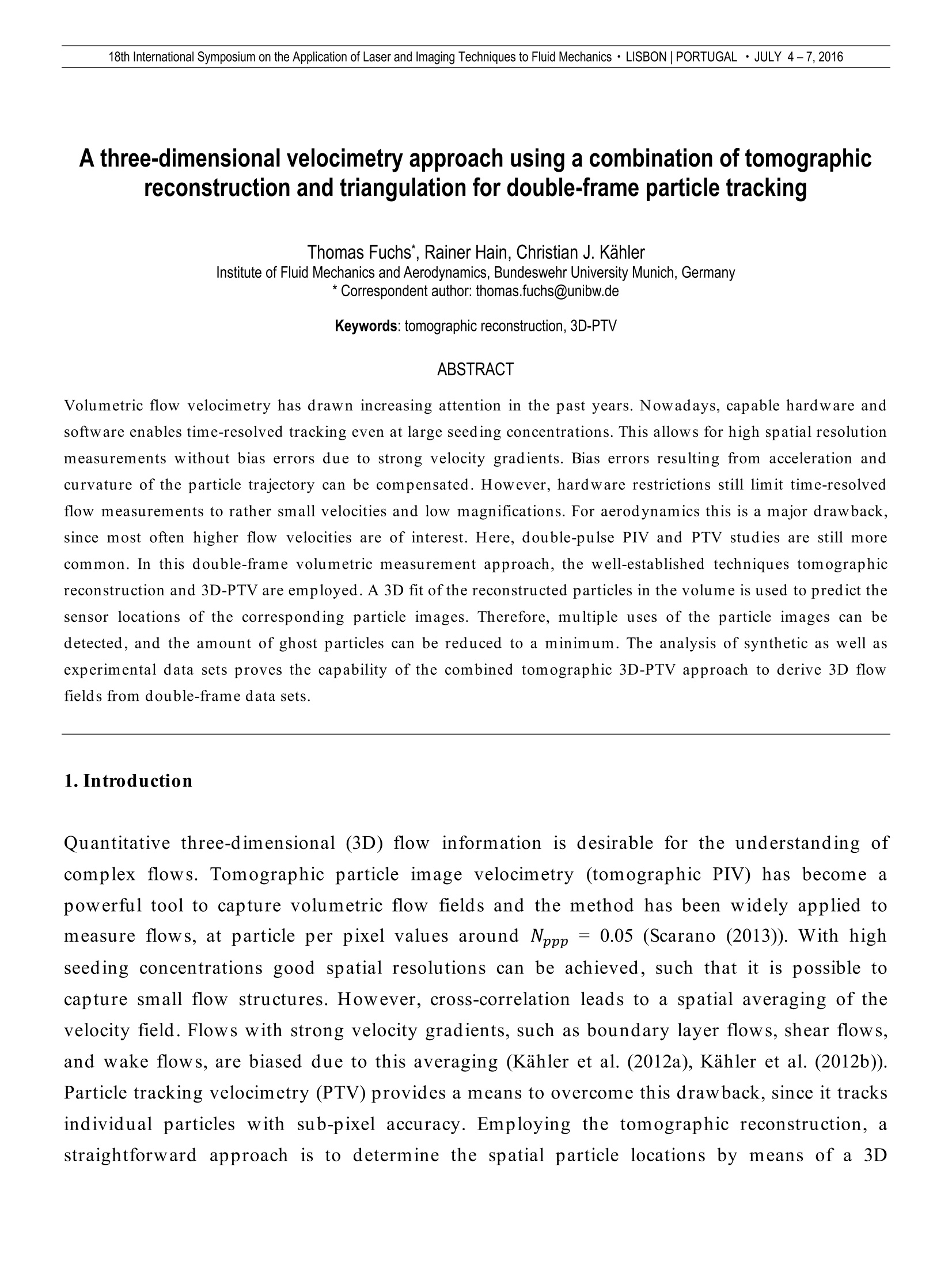
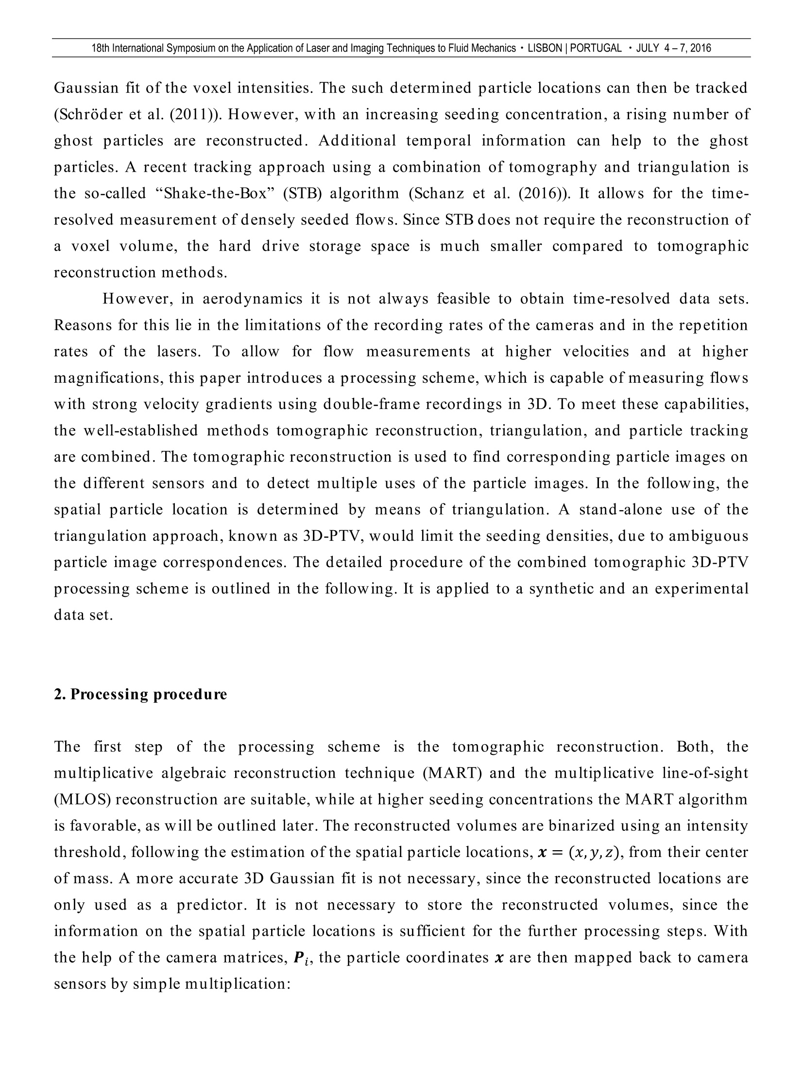
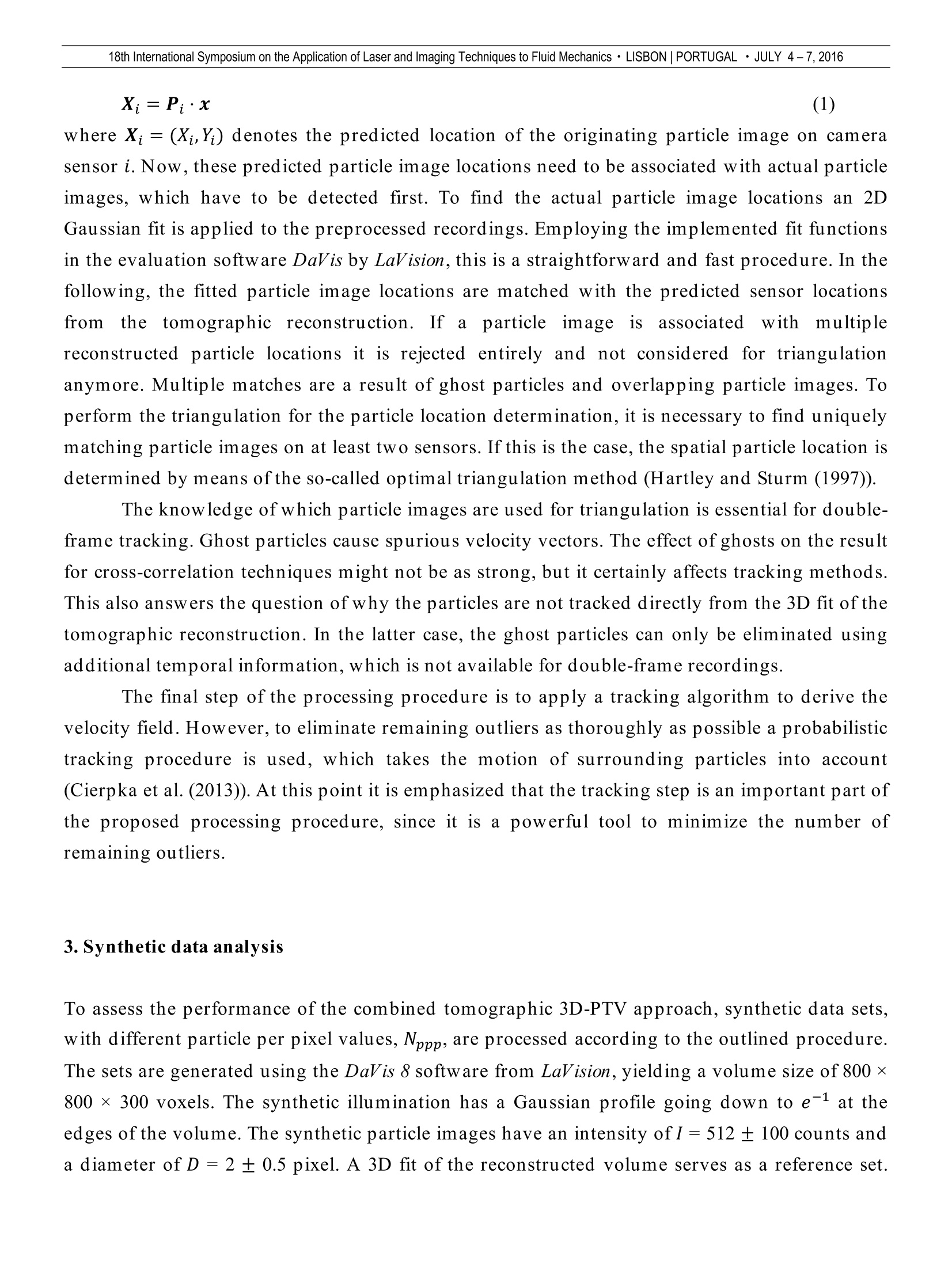
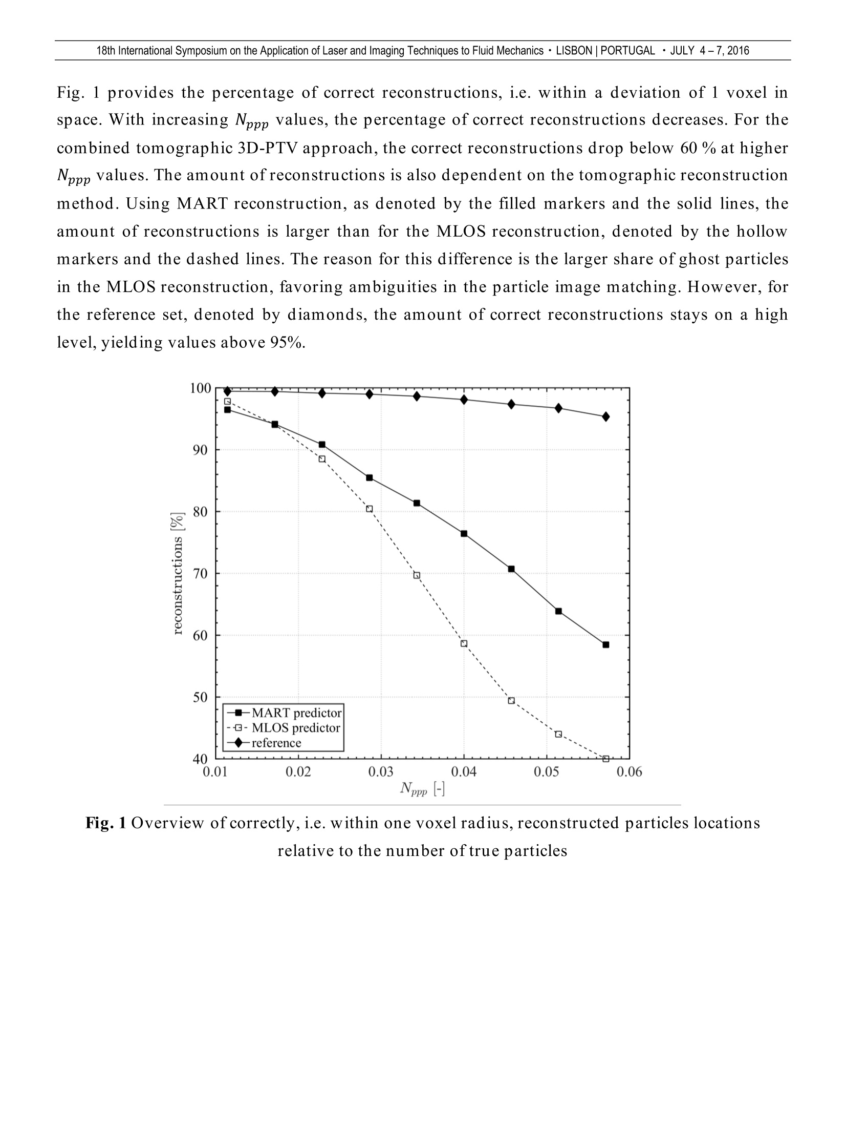
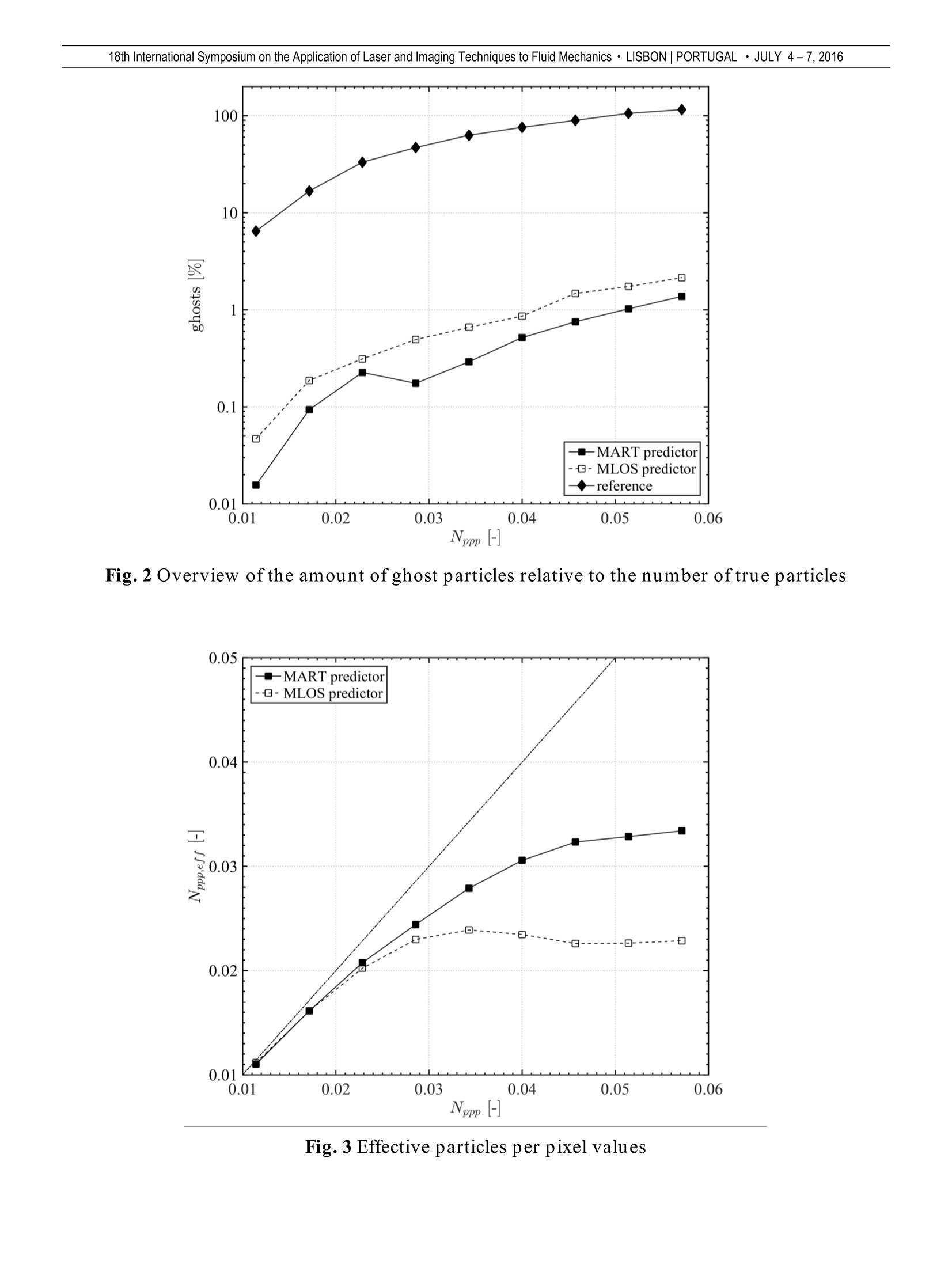
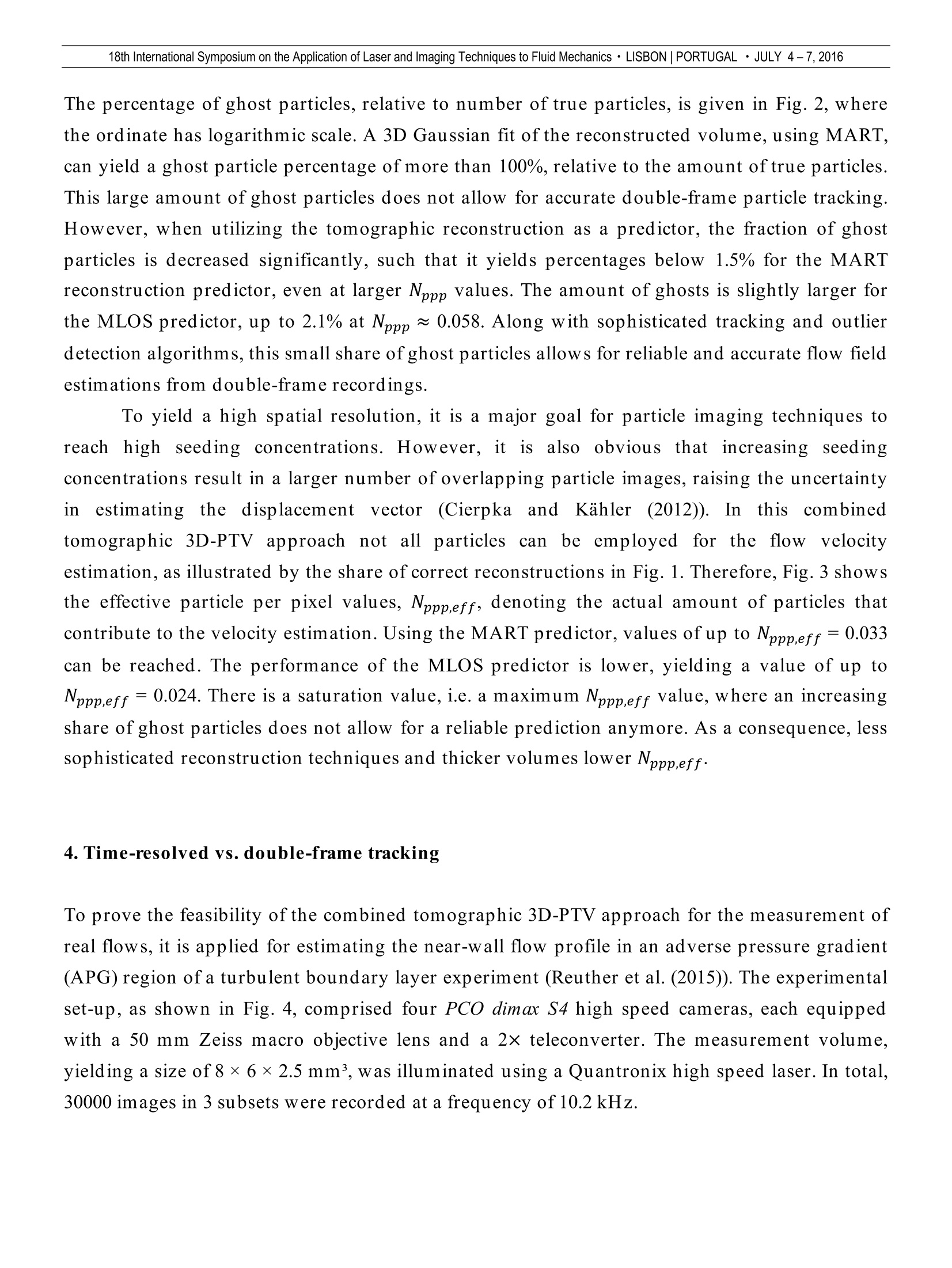
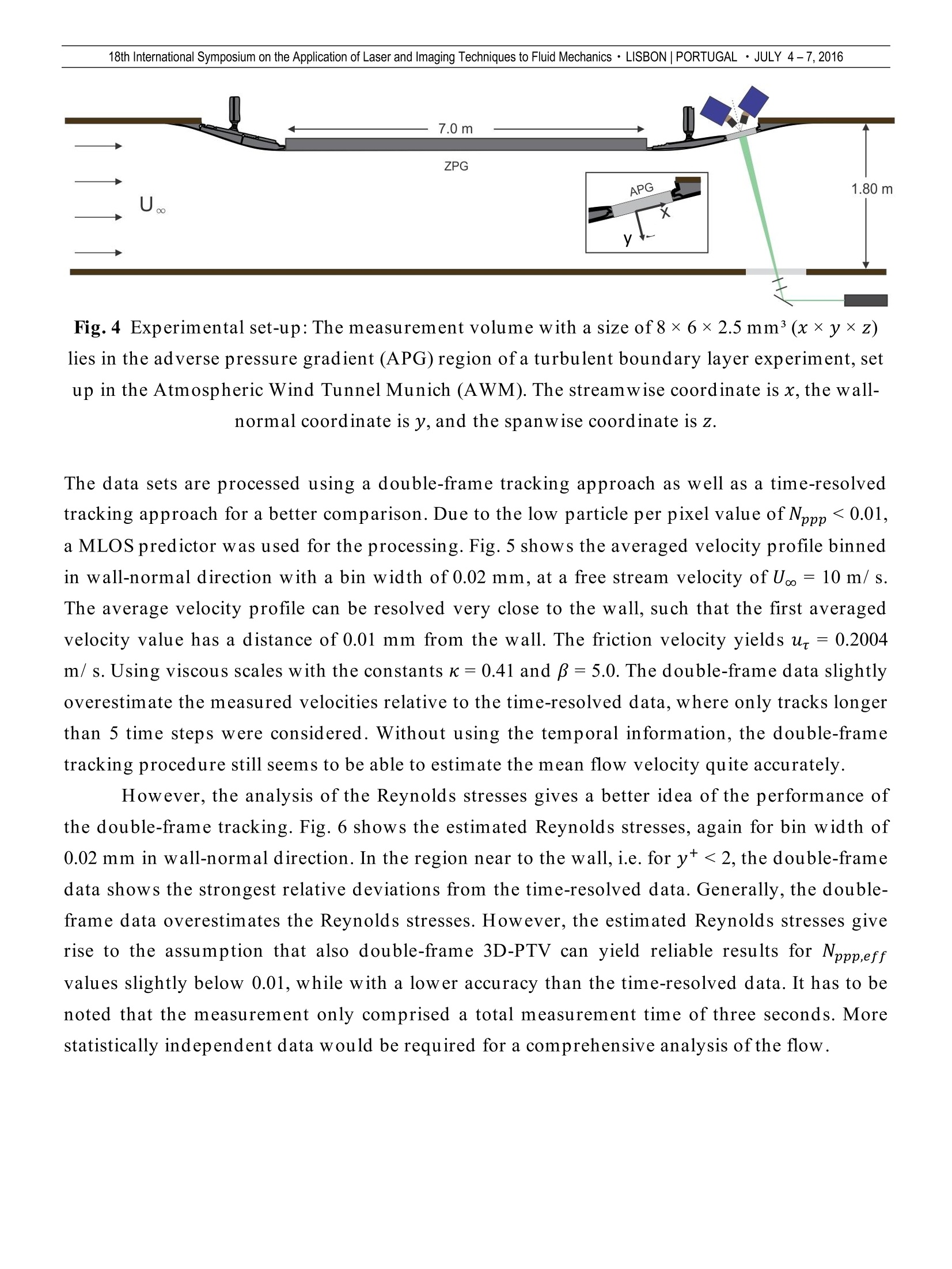
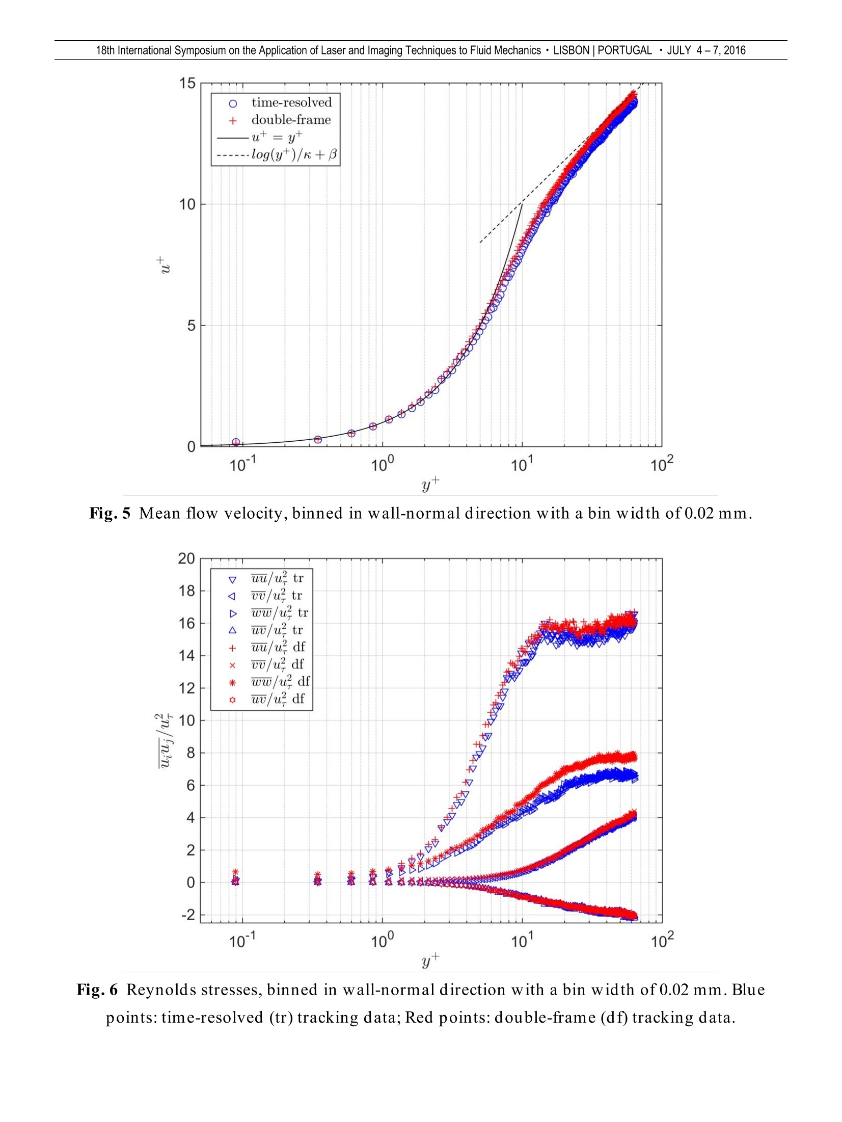
18th International Symposium on the Application of Laser and Imaging Techniques to Fluid Mechanics · LISBON|PORTUGAL · JULY 4-7,2016 A three-dimensional velocimetry approach using a combination of tomographicreconstruction and triangulation for double-frame particle tracking Thomas Fuchs*, Rainer Hain, Christian J. Kahler Institute of Fluid Mechanics and Aerodynamics, Bundeswehr University Munich, Germany * Correspondent author: thomas.fuchs@unibw.de Keywords: tomographic reconstruction, 3D-PTV ABSTRACT Volumetric flow velocimetry has drawn increasing attention in the past years.Nowadays, capable hardware andsoftware enables time-resolved tracking even at large seeding concentrations. This allows for high spatial resolutionmeasurements without bias errors due to strong velocity gradients. Bias errors resulting from acceleration andcurvature of the particle trajectory can be compensated. However, hardware restrictions still limit time-resolvedflow measurements to rather small velocities and low magnifications. For aerodynamics this is a major drawback,since most often higher flow velocities are of interest. Here, double-pulse PIV and PTV studies are still morecommon. In this double-frame volumetric measurement approach, the well-established techniques tomographicreconstruction and 3D-PTV are employed. A 3D fit of the reconstructed particles in the volume is used to predict thesensor locations of the corresponding particle images. Therefore, multiple uses of the particle images can bedetected, and the amount of ghost particles can be reduced to a minimum. The analysis of synthetic as well asexperimental data sets proves the capability of the combined tomographic 3D-PTV approach to derive 3D flowfields from double-frame data sets. 1. Introduction Quantitative three-dimensional (3D) flow information is desirable for the understanding ofcomplex flows.. Tomographic particle image velocimetry (tomographic PIV) has become apowerful tool to capture volumetric flow fields and the method has been widely applied tomeasure flows, at particle per pixel values around Nppp = 0.05 (Scarano (2013)). With highseeding concentrations good spatial resolutions can be achieved, such that it is possible tocapture small flow structures. However, cross-correlation leads to a spatial averaging of thevelocity field. Flows with strong velocity gradients, such as boundary layer flows, shear flows,and wake flows, are biased due to this averaging (Kahler et al. (2012a), Kahler et al. (2012b)).Particle tracking velocimetry (PTV) provides a means to overcome this drawback, since it tracksindividual particles with sub-pixel accuracy. Employing the tomographic reconstruction, astraightforward approach is to determine the spatial particle locations by means of a 3D Gaussian fit of the voxel intensities. The such determined particle locations can then be tracked(Schroder et al. (2011)). However,with an increasing seeding concentration, a rising number ofghost particlesaare reconstructed. Additional temporal information can help to the ghostparticles. A recent tracking approach using a combination of tomography and triangulation isthe so-called “Shake-the-Box”(STB) algorithm (Schanz et al. (2016)). It allows for the time-resolved measurement of densely seeded flows. Since STB does not require the reconstruction ofavoxel volume, the hard drive storage space is much smaller compared to tomographicreconstruction methods. However, in aerodynamics it is not always feasible to obtain time-resolved data sets.Reasons for this lie in the limitations of the recording rates of the cameras and in the repetitionratess of the lasers.To allow fiofior flowvnmeasurementssatthigher velocitiess and at highermagnifications, this paper introduces a processing scheme, which is capable of measuring flowswith strong velocity gradients using double-frame recordings in 3D. To meet these capabilities,the well-established methods tomographic reconstruction, triangulation, and particle trackingare combined. The tomographic reconstruction is used to find corresponding particle images onthe different sensors and to detect multiple uses of the particle images. In the following, thespatial particle location is determined by means of triangulation. A stand-alone use of thetriangulation approach, known as 3D-PTV, would limit the seeding densities, due to ambiguousparticle image correspondences. The detailed procedure of the combined tomographic 3D-PTVprocessing scheme is outlined in the following. It is applied to a synthetic and an experimentaldata set. 2. Processing procedure The first stepof theprocessingscheme iisthee ttomographic reconstruction. Both, themultiplicative algebraic reconstruction technique (MART) and the multiplicative line-of-sight(MLOS) reconstruction are suitable, while at higher seeding concentrations the MART algorithmis favorable, as will be outlined later. The reconstructed volumes are binarized using an intensitythreshold, following the estimation of the spatial particle locations, x= (x,y,z), from their centerof mass. A more accurate 3D Gaussian fit is not necessary,since the reconstructed locations areonly used:asa predictor. It is not necessary to store the reconstructed volumes, since theinformation on the spatial particle locations is sufficient for the further processing steps. Withthe help of the camera matrices, Pi, the particle coordinates x are then mapped back to camerasensors by simple multiplication: where Xi=(X,,Y) denotes the predicted location of the originating particle image on camerasensor i. Now, these predicted particle image locations need to be associated with actual particleimages, which have to be detected first. To find the actual particle image locations an2DGaussian fit is applied to the preprocessed recordings. Employing the implemented fit functionsin the evaluation software DaVis by LaVision, this is a straightforward and fast procedure. In thefollowing, the fitted particle image locations are matched with the predicted sensor locationsfrom1the tomographic reconstruction. If aa particle image isassociatedwith multiplereconstructed particle locations it is rejected entirely and not considered for triangulationanymore. Multiple matches are a result of ghost particles and overlapping particle images. Toperform the triangulation for the particle location determination, it is necessary to find uniquelymatching particle images on at least two sensors. If this is the case, the spatial particle location isdetermined by means of the so-called optimal triangulation method (Hartley and Sturm (1997)). The knowledge of which particle images are used for triangulation is essential for double-frame tracking. Ghost particles cause spurious velocity vectors. The effect of ghosts on the resultfor cross-correlation techniques might not be as strong, but it certainly affects tracking methods.This also answers the question of why the particles are not tracked directly from the 3D fit of thetomographic reconstruction. In the latter case, the ghost particles can only be eliminated usingadditional temporal information, which is not available for double-frame recordings. The final step of the processing procedure is to apply a tracking algorithm to derive thevelocity field. However, to eliminate remaining outliers as thoroughly as possible a probabilistictracking procedure is used, which takes the motion of surrounding particles into account(Cierpka et al. (2013)). At this point it is emphasized that the tracking step is an important part ofthe proposed processing procedure, since it is a powerful tool to minimize the number ofremaining outliers. 3. Synthetic data analysis To assess the performance of the combined tomographic 3D-PTV approach, synthetic data sets,with different particle per pixel values, Nppp, are processed according to the outlined procedure.The sets are generated using the DaV is 8 software from LaVision, yielding a volume size of 800 ×800 ×300 voxels. The synthetic illumination has a Gaussian profile going down to e-1 at theedges of the volume. The synthetic particle images have an intensity ofI = 512 ±100 counts anda diameter of D = 2 ± 0.5 pixel. A 3D fit of the reconstructed volume serves as a reference set. Fig. 1 provides the percentage of correct reconstructions, i.e. within a deviation of 1 voxel inspace. With increasing Nppp values, the percentage of correct reconstructions decreases. For thecombined tomographic 3D-PTV approach, the correct reconstructions drop below 60% at higherNppp values.The amount ofreconstructions is also dependent on the tomographic reconstructionmethod. Using MART reconstruction, as denoted by the filled markers and the solid lines, theamount of reconstructions is larger than for the MLOS reconstruction, denoted by the hollowmarkers and the dashed lines. The reason for this difference is the larger share of ghost particlesin the MLOS reconstruction, favoring ambiguities in the particle image matching.However, forthe reference set, denoted by diamonds, the amount of correct reconstructions stays on a highlevel, yielding values above 95%. Nppp [-] Fig. 1 Overview of correctly, i.e. within one voxel radius, reconstructed particles locationsrelative to the number oftrue particles Fig. 2 Overview of the amount of ghost particles relative to the number of true particles Fig. 3 Effective particles per pixel values The percentage of ghost particles, relative to number of true particles, is given in Fig. 2, wherethe ordinate has logarithmic scale. A 3D Gaussian fit of the reconstructed volume, using MART,can yield a ghost particle percentage of more than 100%, relative to the amount of true particles.This large amount of ghost particles does not allow for accurate double-frame particle tracking.However, when utilizing the tomographic reconstruction as a predictor, the fraction of ghostparticles is decreased significantly, such that it yields percentages below 1.5% for the MARTreconstruction predictor, even at larger Nppp values. The amount of ghosts is slightly larger forthe MLOS predictor, up to 2.1% at Nppp ~0.058. Along with sophisticated tracking and outlierdetection algorithms, this small share of ghost particles allows for reliable and accurate flow fieldestimations from double-frame recordings. To yield a high spatial resolution, it is a major goal for particle imaging techniques toreachhigh seeding concentrations. However, itis; also obvious that increasing seedingconcentrations result in a larger number of overlapping particle images, raising the uncertaintyin estimating the displacementvector(CierpkaandKahle:r(2012)). Inthiscombinedtomographic 3D-PTV approach not all particles can be employed for the flow velocityestimation, as illustrated by the share of correct reconstructions in Fig. 1. Therefore, Fig. 3 showsthe effective particle per pixel values, Nppperf, denoting the actual amount of particles thatcontribute to the velocity estimation. Using the MART predictor, values of up to Npppeff=0.033can be reached. The performance of the MLOS predictor is lower, yielding a value of up toNppp,eff= 0.024. There is a saturation value, i.e. a maximum Nppp,eff value, where an increasingshare of ghost particles does not allow for a reliable prediction anymore. As a consequence, lesssophisticated reconstruction techniques and thicker volumes lower Nppp,eff. 4.Time-resolved vs. double-frame tracking To prove the feasibility of the combined tomographic 3D-PTV approach for the measurement ofreal flows, it is applied for estimating the near-wall flow profile in an adverse pressure gradient(APG) region of a turbulent boundary layer experiment (Reuther et al. (2015)). The experimentalset-up, as shown in Fig. 4, comprised four PCO dimax S4 high speed cameras, each equippedwith a 50 mm Zeiss macro objective lens and a 2× teleconverter. The measurement volume,yielding a size of 8 × 6×2.5 mm’, was illuminated using a Quantronix high speed laser. In total,30000 images in 3 subsets were recorded at a frequency of 10.2 kHz. Fig. 4 Experimental set-up: The measurement volume with a size of8×6×2.5mm³(x×y×z)lies in the adverse pressure gradient (APG) region ofa turbulent boundary layer experiment, setup in the Atmospheric Wind Tunnel Munich (AWM). The streamwise coordinate is x, the wall-normal coordinate is y, and the spanwise coordinate is z. The data sets are processed using a double-frame tracking approach as well as a time-resolvedtracking approach for a better comparison. Due to the low particle per pixel value of Nppp<0.01,a MLOS predictor was used for the processing. Fig.5 shows the averaged velocity profile binnedin wall-normal direction with a bin width of 0.02 mm, at a free stream velocity of U.= 10 m/ s.The average velocity profile can be resolved very close to the wall, such that the first averagedvelocity value has a distance of 0.01 mm from the wall. The friction velocity yields ur=0.2004m/ s. Using viscous scales with the constants k=0.41 and β =5.0. The double-frame data slightlyoverestimate the measured velocities relative to the time-resolved data,where only tracks longerthan 5 time steps were considered. Without using the temporal information, the double-frametracking procedure still seems to be able to estimate the mean flow velocity quite accurately. However, the analysis of the Reynolds stresses gives a better idea of the performance ofthe double-frame tracking. Fig. 6 shows the estimated Reynolds stresses,again for bin width of0.02 mm in wall-normal direction. In the region near to the wall, i.e. for y+<2, the double-framedata shows the strongest relative deviations from the time-resolved data. Generally, the double-frame data overestimates the Reynolds stresses. However, the estimated Reynolds stresses giverise to the assumption that also double-frame 3D-PTV can yield reliable results for Npppeffvalues slightly below 0.01, while with a lower accuracy than the time-resolved data. It has to benoted that the measurement only comprised a total measurement time of three seconds. Morestatistically independent data would be required for a comprehensive analysis ofthe flow. y+ Fig.5 Mean flow velocity, binned in wall-normal direction with a bin width of 0.02 mm. y+ Fig.6 Reynolds stresses, binned in wall-normal direction with a bin width of 0.02 mm. Bluepoints: time-resolved (tr) tracking data; Red points: double-frame (df) tracking data. 5.Conclusion A tomographic predictor enables the use of 3D-PTV for measuring flows with effective particleper pixels values of up to Nppp,eff =0.033, shown for a synthetic data set. The combined 3Dimaging approach limits the fraction of ghost particles to values below 2.1%, allowing fordouble-frame particle tracking. Since the method employs tracking algorithms to determine theflow velocities, it is suitable to resolve strong velocity gradients, as proven by the measurementofa turbulent boundary layer flow measured at a Nppp,eff value of slightly below 0.01. Acknowledgments The investigations were conducted as part of the joint research programme AG Turbo 2020 in theframe of AG Turbo. The work was supported by the Bundesministerium fur Wirtschaft undTechnologie (BMWi) as per resolution of the German Federal Parliament under grant number03ET2013M. The authors gratefully acknowledge AG Turbo and MTU Aero Engines AG for theirsupport and permission to publish this paper. The responsibility for the content lies solely withits authors. References Cierpka C, Kahler CJ (2012) Particle imaging techniques for volumetric three-component (3D3C)velocity measurements in microfluidics. J Vis 15:1-31. Cierpka C, Liitke B, Kahler CJ (2013) Higher order multi-frame particle tracking velocimetry.Exp Fluids 54:1533. Hartley RI, Sturm P (1997) Triangulation. Comput Vis Image Und 68:146-157. Kahler CJ, Scharnowski S, Cierpka C (2012a) On the resolution limit of digital particle imagevelocimetry. Exp Fluids 52:1629-1639. Kahler CJ, Scharnowski S, Cierpka C (2012b) On the uncertainty of digital PIV and PTV nearwalls. Exp Fluids 52:1641-1656. Reuther N, Scharnowski S, Hain R, Schanz D, Schroder A, Kahler CJ (2015) Experimentalinvestigation of adverse pressure gradient turbulent boundary layers by means of large-scale PIV. 11th International Symposium on Particle Image Velocimetry, Santa Barbara, CA USA,September 14-16. Scarano F (2013) Tomographic PIV: principles and practice. Meas Sci Technol 24:012001. Schanz D, Gesemann S, Schroder A (2016) Shake-The-Box: Lagrangian particle tracking at highparticle image densities. Exp Fluids 57:70. Schroder A, Geisler R, Staack K, Elsinga GE, Scarano F, Wieneke B, Henning A, Poelma C,Westerweel J (2011) Eulerian and Lagrangian views of a turbulent boundary layer flow usingtime resolved tomographic PIV. Exp Fluids 50:1071-1091. Volumetric flow velocimetry has drawn increasing attention in the past years. Nowadays, capa ble hardware and software enable s time resolved tracking even at large seeding concentrations. This allows for high spatial resolution measurements without bias errors due to strong velocity gradients. Bias errors resulting from acceleration and curvature of the particle trajectory can b e compensated. However, hardware restrictions still limit time resolved flow measurements to rather small velocities and low magnifications. For aerodynamic s this is a major drawback since most often higher flow velocities are of interest Here double pulse PIV and PTV studies are still more common. In this double frame volumetric measurement approach, the well established techniques tomographicreconstruction and 3D PTV are employed. A 3D fit of the r econstruct ed particles in the volume is used to predict the sensor locations of t he corresponding particle images Therefore, multiple uses of the particle images can be detected and the amount of ghost particles can be reduced to a minimum The analysis of synthetic as well as experimental data sets proves the capability of the combined tom ographic 3D PTV approach to derive 3D flowfields from double frame data sets1.
确定
还剩8页未读,是否继续阅读?
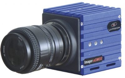
北京欧兰科技发展有限公司为您提供《风洞中3D3C速度矢量场检测方案(CCD相机)》,该方案主要用于航空中3D3C速度矢量场检测,参考标准--,《风洞中3D3C速度矢量场检测方案(CCD相机)》用到的仪器有Imager sCMOS PIV相机、体视层析粒子成像测速系统(Tomo-PIV)、LaVision DaVis 智能成像软件平台
推荐专场
CCD相机/影像CCD
更多
相关方案
更多
该厂商其他方案
更多
