


采用LaVision公司的平面激光诱导荧光(PLIF)测试系统和以DaVis软件平台为基础构成的粒子成像测速(PIV)系统对直喷火花塞引燃(DISI)发动机工作在分层燃烧模式下燃料充量运动和混合物形成的周期性起伏现象进行了观测和研究。
方案详情

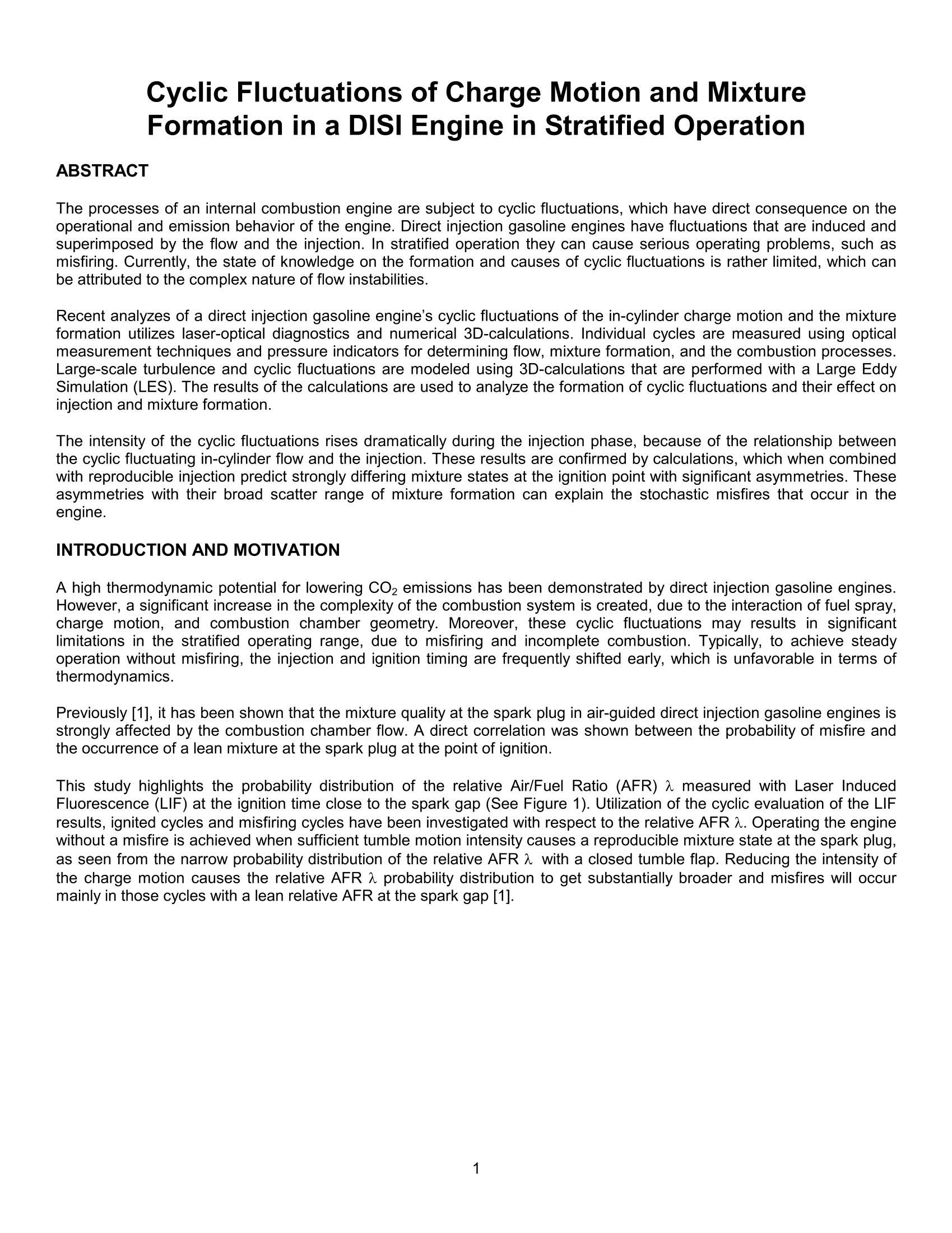
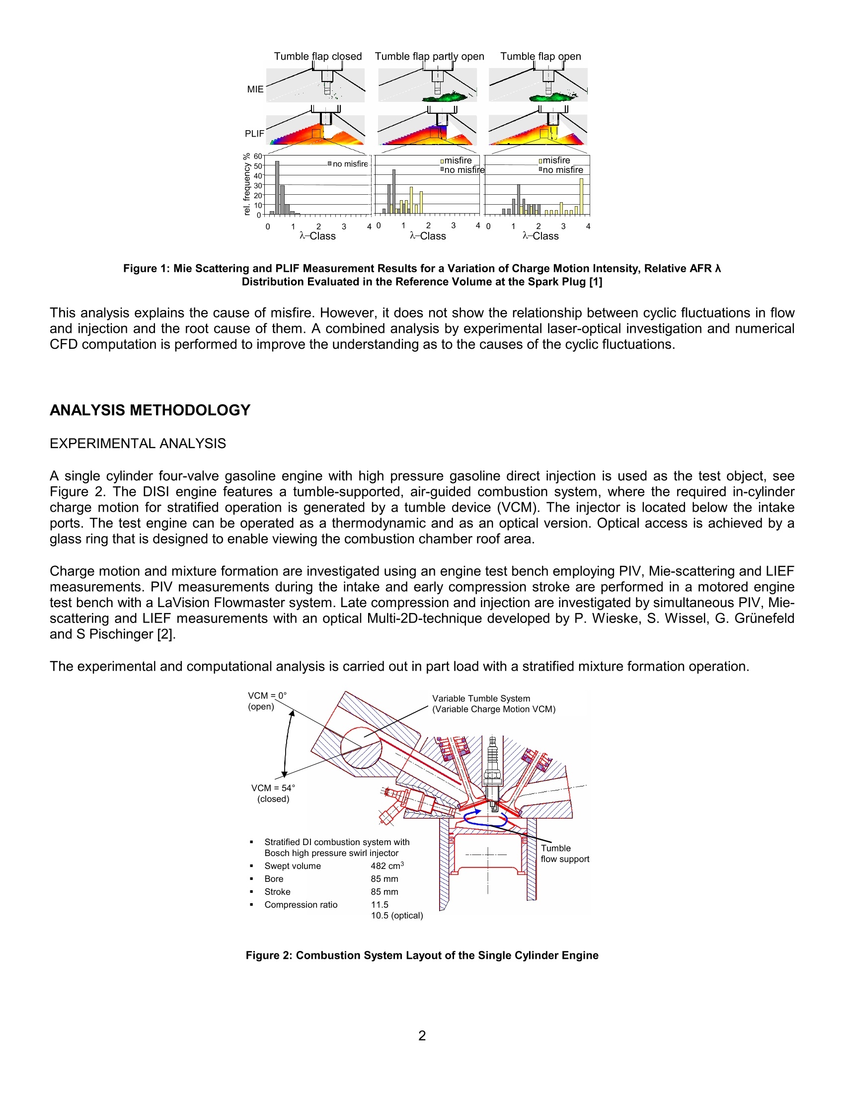
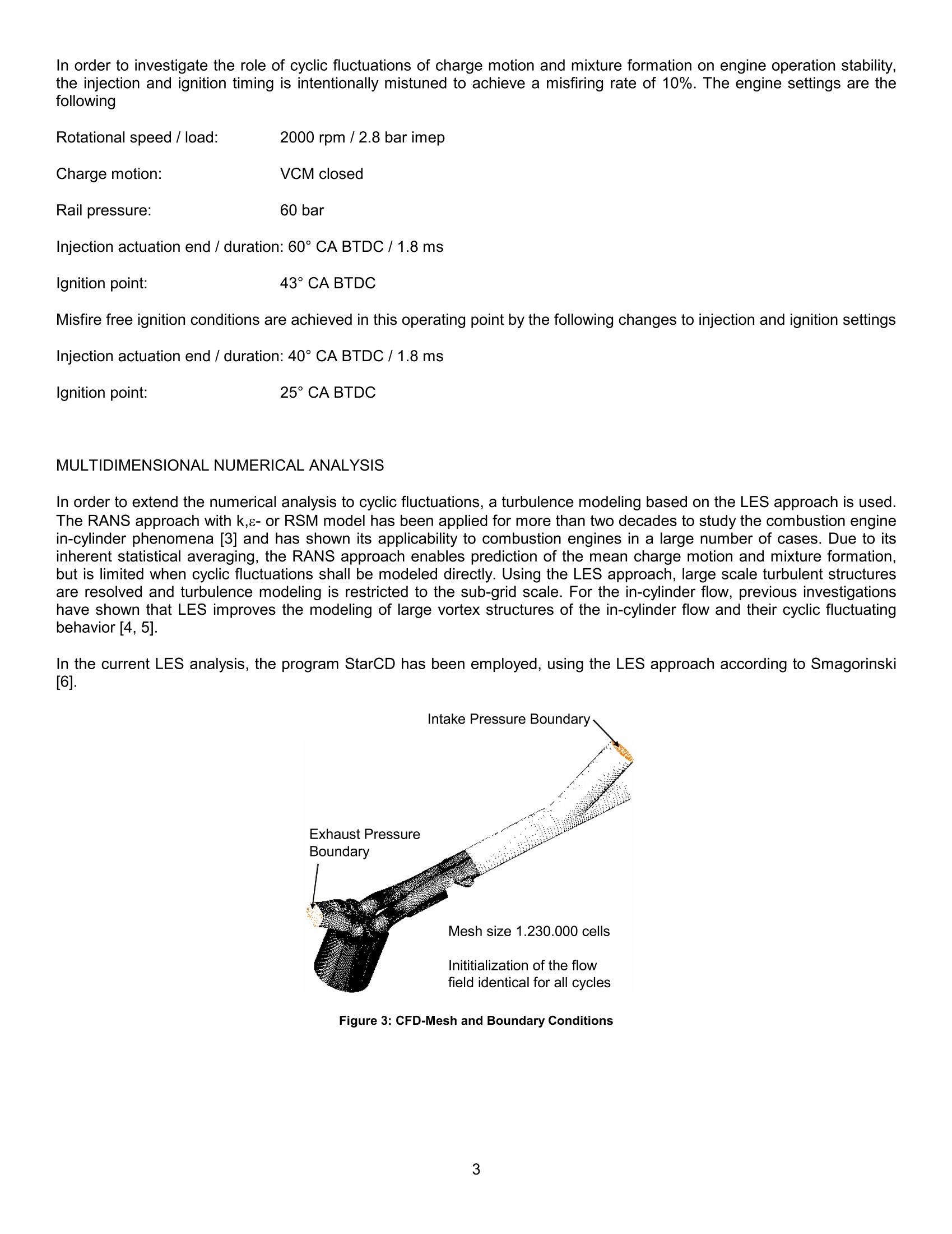
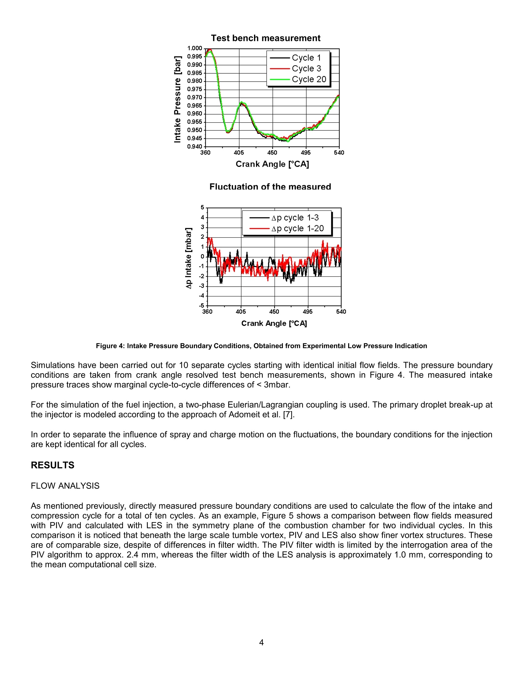
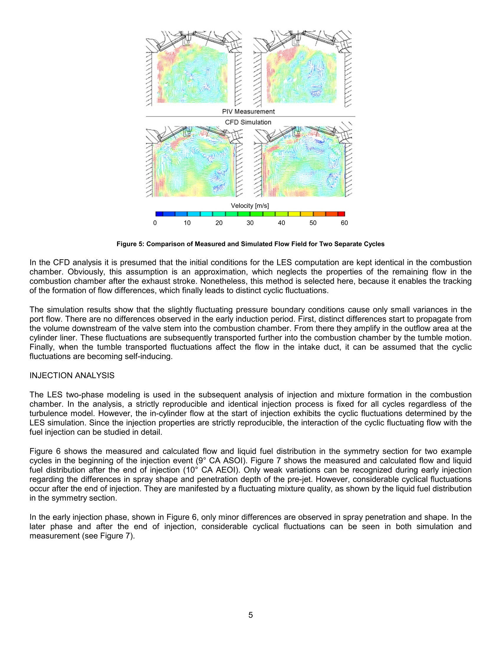
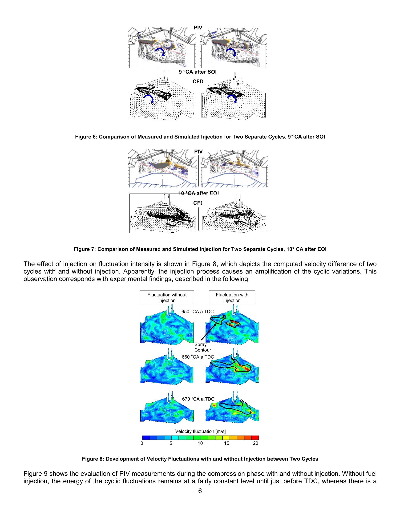
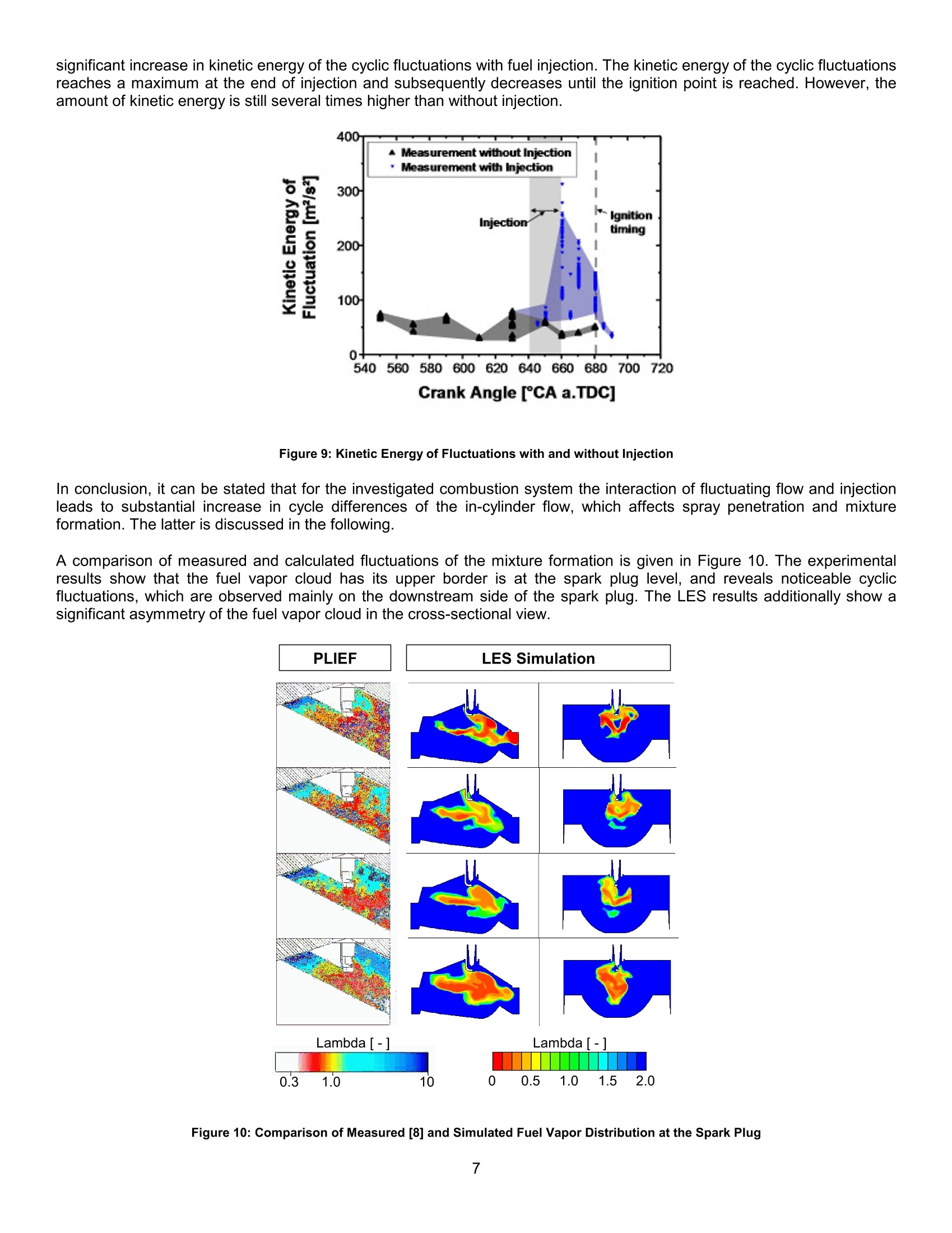
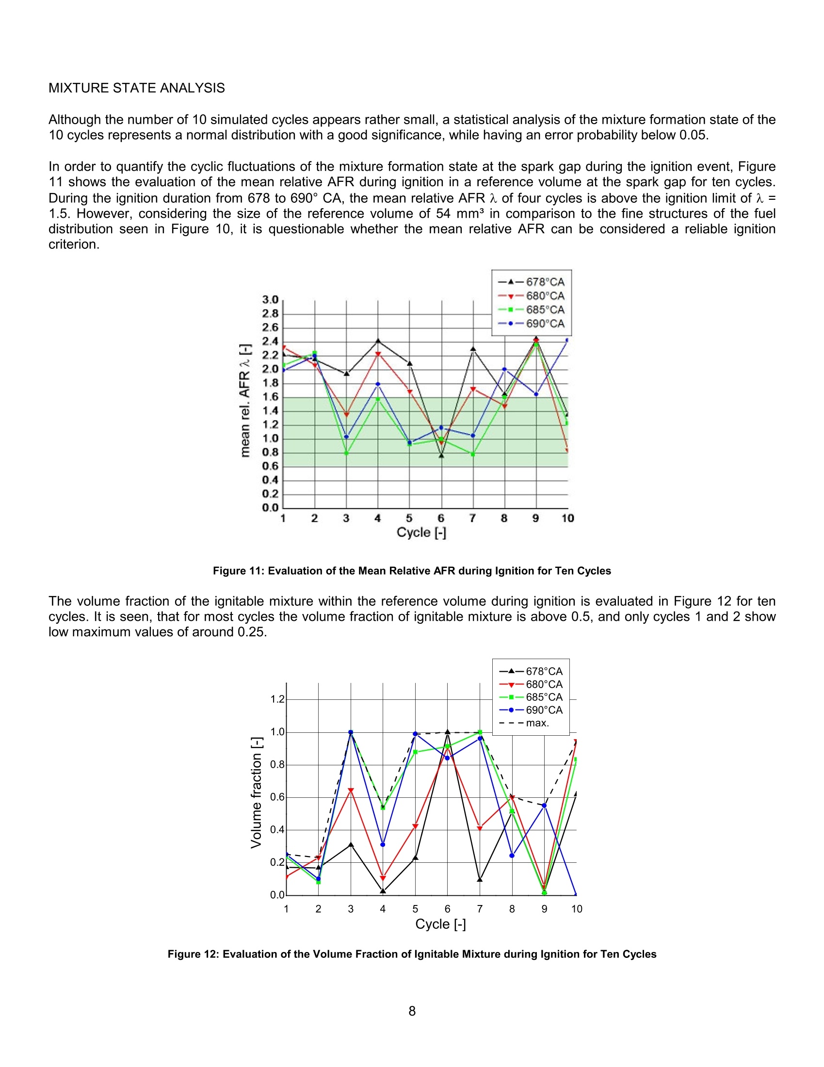
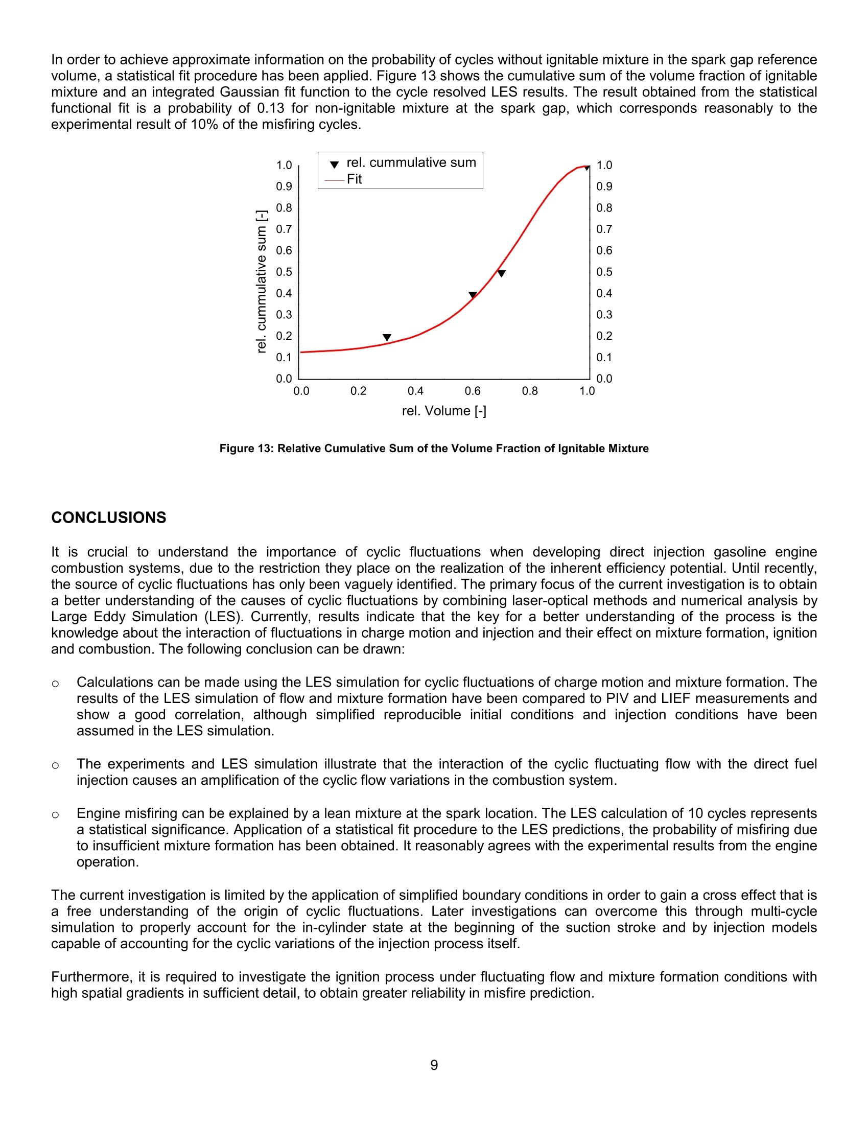
Cyclic Fluctuations of Charge Motion and MixtureFormation in a DISI Engine in Stratified Operation ABSTRACT The processes of an internal combustion engine are subject to cyclic fluctuations, which have direct consequence on theoperational and emission behavior of the engine. Direct injection gasoline engines have fluctuations that are induced andsuperimposed by the flow and the injection. In stratified operation they can cause serious operating problems, such asmisfiring. Currently, the state of knowledge on the formation and causes of cyclic fluctuations is rather limited, which canbe attributed to the complex nature of flow instabilities. Recent analyzes of a direct injection gasoline engine's cyclic fluctuations of the in-cylinder charge motion and the mixtureformation utilizes laser-optical diagnostics and numerical 3D-calculations. Individual cycles are measured using opticalmeasurement techniques and pressure indicators for determining flow, mixture formation, and the combustion processes.Large-scale turbulence and cyclic fluctuations are modeled using 3D-calculations that are performed with a Large EddySimulation (LES). The results of the calculations are used to analyze the formation of cyclic fluctuations and their effect oninjection and mixture formation. The intensity of the cyclic fluctuations rises dramatically during the injection phase, because of the relationship betweenthe cyclic fluctuating in-cylinder flow and the injection. These results are confirmed by calculations, which when combinedwith reproducible injection predict strongly differing mixture states at the ignition point with significant asymmetries. Theseasymmetries with their broad scatter range of mixture formation can explain the stochastic misfires that occur in theengine. INTRODUCTION AND MOTIVATION A high thermodynamic potential for lowering CO2 emissions has been demonstrated by direct injection gasoline engines.However, a significant increase in the complexity of the combustion system is created, due to the interaction of fuel spray,charge motion, and combustion chamber geometry. Moreover, these cyclic fluctuations may results in significantlimitations in the stratified oper.a:ting range, due to misfiring and incomplete combustion. Typically, to achieve steadyoperation without misfiring, the injection and ignition timing are frequently shifted early, which is unfavorable in terms ofthermodynamics. Previously[1], it has been shown that the mixture quality at the spark plug in air-guided direct injection gasoline engines isstrongly affected by the combustion chamber flow. A direct correlation was shown between the probability of misfire andthe occurrence of a lean mixture at the spark plug at the point of ignition. This study highlights the probability distribution of the relative Air/Fuel Ratio (AFR) A measured with Laser InducedFluorescence (LIF) at the ignition time close to the spark gap (See Figure 1). Utilization of the cyclic evaluation of the LIFresults, ignited cycles and misfiring cycles have been investigated with respect to the relative AFR A. Operating the enginewithout a misfire is achieved when sufficient tumble motion intensity causes a reproducible mixture state at the spark plug,as seen from the narrow probability distribution of the relative AFR A with a closed tumble flap. Reducing the intensity ofthe charge motion causes the relative AFR A probability distribution to get substantially broader and misfires will occurmainly in those cycles with a lean relative AFR at the spark gap [1]. Figure 1: Mie Scattering and PLIF Measurement Results for a Variation of Charge Motion Intensity, Relative AFR 入Distribution Evaluated in the Reference Volume at the Spark Plug [1] This analysis explains the cause of misfire. However, it does not show the relationship between cyclic fluctuations in flowand injection and the root cause of them. A combined analysis by experimental laser-optical investigation and numericalCFD computation is performed to improve the understanding as to the causes of the cyclic fluctuations. ANALYSIS METHODOLOGY EXPERIMENTAL ANALYSIS A single cylinder four-valve gasoline engine with high pressure gasoline direct injection is used as the test object, seeFigure 2. The DIsI engine features a tumble-supported, air-guided combustion system, where the required in-cylindercharge motion for stratified operation is generated by a tumble device (VCM). The injector is located below the intakeports. The test engine can be operated as a thermodynamic and as an optical version. Optical access is achieved by aglass ring that is designed to enable viewing the combustion chamber roof area. Charge motion and mixture formation are investigated using an engine test bench employing PIV, Mie-scattering and LIEFmeasurements. PIV measurements during the intake and early compression stroke are performed in a motored enginetest bench with a LaVision Flowmaster system. Late compression and injection are investigated by simultaneous PIV, Mie-scattering and LIEF measurements with an optical Multi-2D-technique developed by P. Wieske, S. Wissel, G. Grunefeldand S Pischinger [2]. The experimental and computational analysis is carried out in part load with a stratified mixture formation operation. Figure 2: Combustion System Layout of the Single Cylinder Engine In order to investigate the role of cyclic fluctuations of charge motion and mixture formation on engine operation stability,the injection and ignition timing is intentionally mistuned to achieve a misfiring rate of 10%. The engine settings are thefollowing Rotational speed / load: 2000 rpm /2.8 bar imep Charge motion: VCM closed Rail pressure: 60 bar Injection actuation end / duration: 60°CA BTDC / 1.8 ms Ignition point: 43° CA BTDC Misfire free ignition conditions are achieved in this operating point by the following changes to injection and ignition settingsInjection actuation end / duration: 40°CA BTDC / 1.8 ms Ignition point: 25°CA BTDC MULTIDIMENSIONAL NUMERICAL ANALYSIS In order to extend the numerical analysis to cyclic fluctuations, a turbulence modeling based on the LES approach is used.The RANS approach with k,s-or RSM model has been applied for more than two decades to study the combustion enginein-cylinder phenomena [3] and has shown its applicability to combustion engines in a large number of cases. Due to itsinherent statistical averaging, the RANS approach enables prediction of the mean charge motion and mixture formation,but is limited when cyclic fluctuations shall be modeled directly. Using the LES approach, large scale turbulent structuresare resolved and turbulence modeling is restricted to the sub-grid scale. For the in-cylinder flow, previous investigationshave shown that LES improves the modeling of large vortex structures of the in-cylinder flow and their cyclic fluctuatingbehavior [4, 5]. In the current LES analysis, the program StarCD has been employed, using the LES approach according to Smagorinski[6]. Figure 3: CFD-Mesh and Boundary Conditions Test bench measurement Crank Ang le [CA] Fluctuation of the measured Figure 4: Intake Pressure Boundary Conditions, Obtained from Experimental Low Pressure Indication Simulations have been carried out for 10 separate cycles starting with identical initial flow fields. The pressure boundaryconditions are taken from crank angle resolved test bench measurements, shown in Figure 4. The measured intakepressure traces show marginal cycle-to-cycle differences of <3mbar. For the simulation of the fuel injection, a two-phase Eulerian/Lagrangian coupling is used. The primary droplet break-up atthe injector is modeled according to the approach of Adomeit et al. [7]. In order to separate the influence of spray and charge motion on the fluctuations, the boundary conditions for the injectionare kept identical for all cycles. RESULTS FLOW ANALYSIS As mentioned previously, directly measured pressure boundary conditions are used to calculate the flow of the intake andcompression cycle for a total of ten cycles. As an example, Figure 5 shows a comparison between flow fields measuredwith PlV and calculated with LES in the symmetry plane of the combustion chamber for two individual cycles. In thiscomparison it is noticed that beneath the large scale tumble vortex, PIV and LES also show finer vortex structures. Theseare of comparable size, despite of differences in filter width. The PIV filter width is limited by the interrogation area of thePIV algorithm to approx. 2.4 mm, whereas the filter width of the LES analysis is approximately 1.0 mm, corresponding tothe mean computational cell size. Figure 5: Comparison of Measured and Simulated Flow Field for Two Separate Cycles In the CFD analysis it is presumed that the initial conditions for the LES computation are kept identical in the combustionchamber. Obviously, this assumption is an approximation, which neglects the properties of the remaining flow in thecombustion chamber after the exhaust stroke. Nonetheless, this method is selected here, because it enables the trackingof the formation of flow differences, which finally leads to distinct cyclic fluctuations. The simulation results show that the slightly fluctuating pressure boundary conditions cause only small variances in theport flow. There are no differences observed in the early induction period. First, distinct differences start to propagate fromthe volume downstream of the valve stem into the combustion chamber. From there they amplify in the outflow area at thecylinder liner. These fluctuations are subsequently transported further into the combustion chamber by the tumble motion.Finally, when the tumble transported fluctuations affect the flow in the intake duct, it can be assumed that the cyclicfluctuations are becoming self-inducing. INJECTION ANALYSIS The LES two-phase modeling is used in the subsequent analysis of injection and mixture formation in the combustionchamber. In the analysis, a strictly reproducible and identical injection process is fixed for all cycles regardless of theturbulence model. However, the in-cylinder flow at the start of injection exhibits the cyclic fluctuations determined by theLES simulation. Since the injection properties are strictly reproducible, the interaction of the cyclic fluctuating flow with thefuel injection can be studied in detail. Figure 6 shows the measured and calculated flow and liquid fuel distribution in the symmetry section for two examplecycles in the beginning of the injection event (9°CA ASOI). Figure 7 shows the measured and calculated flow and liquidfuel distribution after the end of injection (10°CA AEOl). Only weak variations can be recognized during early injectionregarding the differences in spray shape and penetration depth of the pre-jet. However, considerable cyclical fluctuationsoccur after the end of injection. They are manifested by a fluctuating mixture quality, as shown by the liquid fuel distributionin the symmetry section. In the early injection phase, shown in Figure 6,only minor differences are observed in spray penetration and shape. In thelater phase and after the end of injection, considerable cyclical fluctuations can be seen in both simulation andmeasurement (see Figure 7). Figure 6: Comparison of Measured and Simulated Injection for Two Separate Cycles, 9°CA after SOI PIV Figure 7: Comparison of Measured and Simulated Injection for Two Separate Cycles, 10° CA after EOl The effect of injection on fluctuation intensity is shown in Figure 8, which depicts the computed velocity difference of twocycles with and without injection. Apparently, the injection process causes an amplification of the cyclic variations. Thisobservation corresponds with experimental findings, described in the following. Figure 8: Development of Velocity Fluctuations with and without Injection between Two Cycles Figure 9 shows the evaluation of PIV measurements during the compression phase with and without injection. Without fuelinjection, the energy of the cyclic fluctuations remains at a fairly constant level until just before TDC, whereas there is a significant increase in kinetic energy of the cyclic fluctuations with fuel injection. The kinetic energy of the cyclic fluctuationsreaches a maximum at the end of injection and subsequently decreases until the ignition point is reached. However, theamount of kinetic energy is still several times higher than without injection. Figure 9: Kinetic Energy of Fluctuations with and without Injection In conclusion, it can be stated that for the investigated combustion system the interaction of fluctuating flow and injectionleads to substantial increase in cycle differences of the in-cylinder flow, which affects spray penetration and mixtureformation. The latter is discussed in the following. A comparison of measured and calculated fluctuations of the mixture formation is given in Figure 10. The experimentalresults show that the fuel vapor cloud has its upper border is at the spark plug level, and reveals noticeable cyclicfluctuations, which are observed mainly on the downstream side of the spark plug. The LES results additionally show asignificant asymmetry of the fuel vapor cloud in the cross-sectional view. Figure 10: Comparison of Measured [8] and Simulated Fuel Vapor Distribution at the Spark Plug MIXTURE STATE ANALYSIS Although the number of 10 simulated cycles appears rather small, a statistical analysis of the mixture formation state of the10 cycles represents a normal distribution with a good significance, while having an error probability below 0.05. In order to quantify the cyclic fluctuations of the mixture formation state at the spark gap during the ignition event, Figure11 shows the evaluation of the mean relative AFR during ignition in a reference volume at the spark gap for ten cycles.During the ignition duration from 678 to 690°CA, the mean relative AFR A of four cycles is above the ignition limit of =1.5. However, considering the size of the reference volume of 54 mm3 in comparison to the fine structures of the fueldistribution seen in Figure 10, it is questionable whether the mean relative AFR can be considered a reliable ignitioncriterion. Figure 11: Evaluation of the Mean Relative AFR during Ignition for Ten Cycles The volume fraction of the ignitable mixture within the reference volume during ignition is evaluated in Figure 12 for tencycles. It is seen, that for most cycles the volume fraction of ignitable mixture is above 0.5, and only cycles 1 and 2 showlow maximum values of around 0.25. Figure 12: Evaluation of the Volume Fraction of Ignitable Mixture during Ignition for Ten Cycles In order to achieve approximate information on the probability of cycles without ignitable mixture in the spark gap referencevolume, a statistical fit procedure has been applied. Figure 13 shows the cumulative sum of the volume fraction of ignitablemixture and an integrated Gaussian fit function to the cycle resolved LES results. The result obtained from the statisticalfunctional fit is a probability of 0.13 for non-ignitable mixture at the spark gap, which corresponds reasonably to theexperimental result of 10% of the misfiring cycles. Figure 13: Relative Cumulative Sum of the Volume Fraction of Ignitable Mixture CONCLUSIONS It is crucial to understand the importance of cyclic fluctuations when developing direct injection gasoline enginecombustion systems, due to the restriction they place on the realization of the inherent efficiency potential. Until recently,the source of cyclic fluctuations has only been vaguely identified. The primary focus of the current investigation is to obtaina better understanding of the causes of cyclic fluctuations by combining laser-optical methods and numerical analysis byLarge Eddy Simulation (LES). Currently, results indicate that the key for a better understanding of the process is theknowledge about the interaction of fluctuations in charge motion and injection and their effect on mixture formation, ignitionand combustion. The following conclusion can be drawn: Calculations can be made using the LES simulation for cyclic fluctuations of charge motion and mixture formation. Theresults of the LES simulation of flow and mixture formation have been compared to PlV and LIEF measurements andshow a good correlation, although simplified reproducible initial conditions and injection conditions have beenassumed in the LES simulation. 0 The experiments and LES simulation illustrate that the interaction of the cyclic fluctuating flow with the direct fuelinjection causes an amplification of the cyclic flow variations in the combustion system. Engine misfiring can be explained by a lean mixture at the spark location. The LES calculation of 10 cycles representsa statistical significance. Application of a statistical fit procedure to the LES predictions, the probability of misfiring dueto insufficient mixture formation has been obtained. It reasonably agrees with the experimental results from the engineoperation. The current investigation is limited by the application of simplified boundary conditions in order to gain a cross effect that isa free understanding of the origin of cyclic fluctuations. Later investigations can overcome this through multi-cyclesimulation to properly account for the in-cylinder state at the beginning of the suction stroke and by injection modelscapable of accounting for the cyclic variations of the injection process itself. Furthermore, it is required to investigate the ignition process under fluctuating flow and mixture formation conditions withhigh spatial gradients in sufficient detail, to obtain greater reliability in misfire prediction. ACKNOWLEDGEMENTS The authors thank the Federal Ministry of Education and Research of Germany, BMBF for the financial support, whichenabled this project. The work reported here was sponsored with funds of the Federal Ministry of Education and Researchunder the sign 03PIA1AC. The responsibility for the content of this publication lies with the authors. REFERENCES [1] Adomeit, P., Geiger, J., Herrmann, H.-O., Ballauf, J., Becker, M., Vogt, B., Greis, A.: Laseroptical diagnostics andnumerical analysis of modern DI-combustion systems, 5th Int. Symposium for Combustion Diagnostics (ed. Ziegler, P.)06.-07.06.2002, Baden-Baden [2] Wieske P., Wissel S., Grunefeld G., Pischinger S.: Improvement of LIEF by wavelength-resolved acquisition of multipleimages using a single CCD detector - Simultaneous 2D measurement of air/fuel ratio, temperature distribution of theliquid phase and qualitative distribution of the liquid phase with the Multi-2D technique. J. Applied Physics B, vol. 83(2),323-329,2006 ( [3] Thary E.S.H.: Application of a Reynolds Stress Model to Engine Flow Calculations, J. Fluids Eng. 107, 444-450, 1985 ) ( [4] Haworth D.: Large Eddy Simulation o f In-Cylinder Flows, Oil and Gas Sci . Techn. Rev. IFP, 1999 ) ( [5] Celik 1. , Yavuz 1., Smirov A.: Large e ddy s i mulations of the in-cylinder t u rbulence for internal combustion engines: areview, Int.J . Engin e Res. Vol.2(2), 119-148,2001 ) ( [6] Smagorinski, J.: G eneral c i rculation experiments wi t h the pr i mitive equations. I. The ba s ic experiment. Mon.WeatherRev., 1963,v.91(3),99-164 ) ( [7] Adomeit, P ., Lang, O. und Pischinger S.: S p ray pr o pagation and mix t ure formation in an air g ui d ed direct inj e ctiongasoline e ngine. I nt. J. Engine Research, 2000, v o l.1 ( 2), 163-170 ) [8] Wieske P., Grunefeld G.: Measurement of the fuel distribution as liquid and gas phase by Laser Induced ExciplexFluoreszence (LIEF) (in German). BMBF Workshop Turbulenz in der Energietechnik, 06.06.2005, Darmstadt CONTACT P. Adomeit, FEV Motorentechnik GmbH, 52078 Aachen,Germany; ++49 241 5689-434; Email: Adomeit@fev.de The processes of an internal combustion engine are subject to cyclic fluctuations, which have direct consequence on theoperational and emission behavior of the engine. Direct injection gasoline engines have fluctuations that are induced andsuperimposed by the flow and the injection. In stratified operation they can cause serious operating problems, such asmisfiring. Currently, the state of knowledge on the formation and causes of cyclic fluctuations is rather limited, which canbe attributed to the complex nature of flow instabilities.Recent analyzes of a direct injection gasoline engine’s cyclic fluctuations of the in-cylinder charge motion and the mixtureformation utilizes laser-optical diagnostics and numerical 3D-calculations. Individual cycles are measured using opticalmeasurement techniques and pressure indicators for determining flow, mixture formation, and the combustion processes.Large-scale turbulence and cyclic fluctuations are modeled using 3D-calculations that are performed with a Large EddySimulation (LES). The results of the calculations are used to analyze the formation of cyclic fluctuations and their effect oninjection and mixture formation.The intensity of the cyclic fluctuations rises dramatically during the injection phase, because of the relationship betweenthe cyclic fluctuating in-cylinder flow and the injection. These results are confirmed by calculations, which when combinedwith reproducible injection predict strongly differing mixture states at the ignition point with significant asymmetries. Theseasymmetries with their broad scatter range of mixture formation can explain the stochastic misfires that occur in theengine.
确定
还剩8页未读,是否继续阅读?

产品配置单


北京欧兰科技发展有限公司为您提供《直喷火花塞引燃(DISI)发动机中燃料充量运动和混合物形成的周期性起伏检测方案(流量计)》,该方案主要用于汽车电子电器中热性能检测,参考标准--,《直喷火花塞引燃(DISI)发动机中燃料充量运动和混合物形成的周期性起伏检测方案(流量计)》用到的仪器有PLIF平面激光诱导荧光火焰燃烧检测系统、德国LaVision PIV/PLIF粒子成像测速场仪、汽车发动机多参量测试系统、LaVision SprayMaster 喷雾成像测量系统
推荐专场


汽车尾气分析仪
更多


该厂商其他方案
更多