


采用LaVision公司已图像增强器为核心搭建的平面激光诱导荧光测试系统和喷雾分析系统,定量地研究了丙烷/液化石油气喷雾结构及其和环境压力的关系。
方案详情

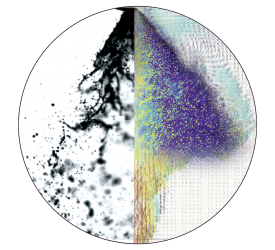
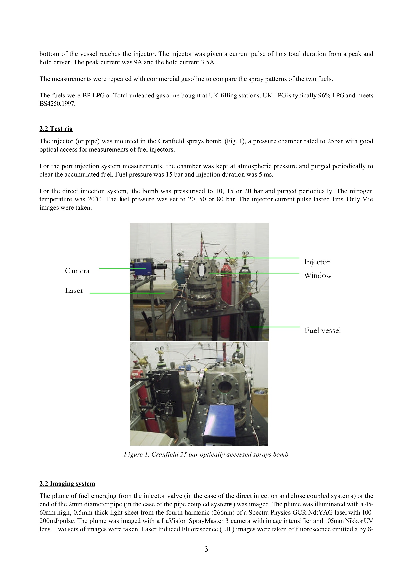
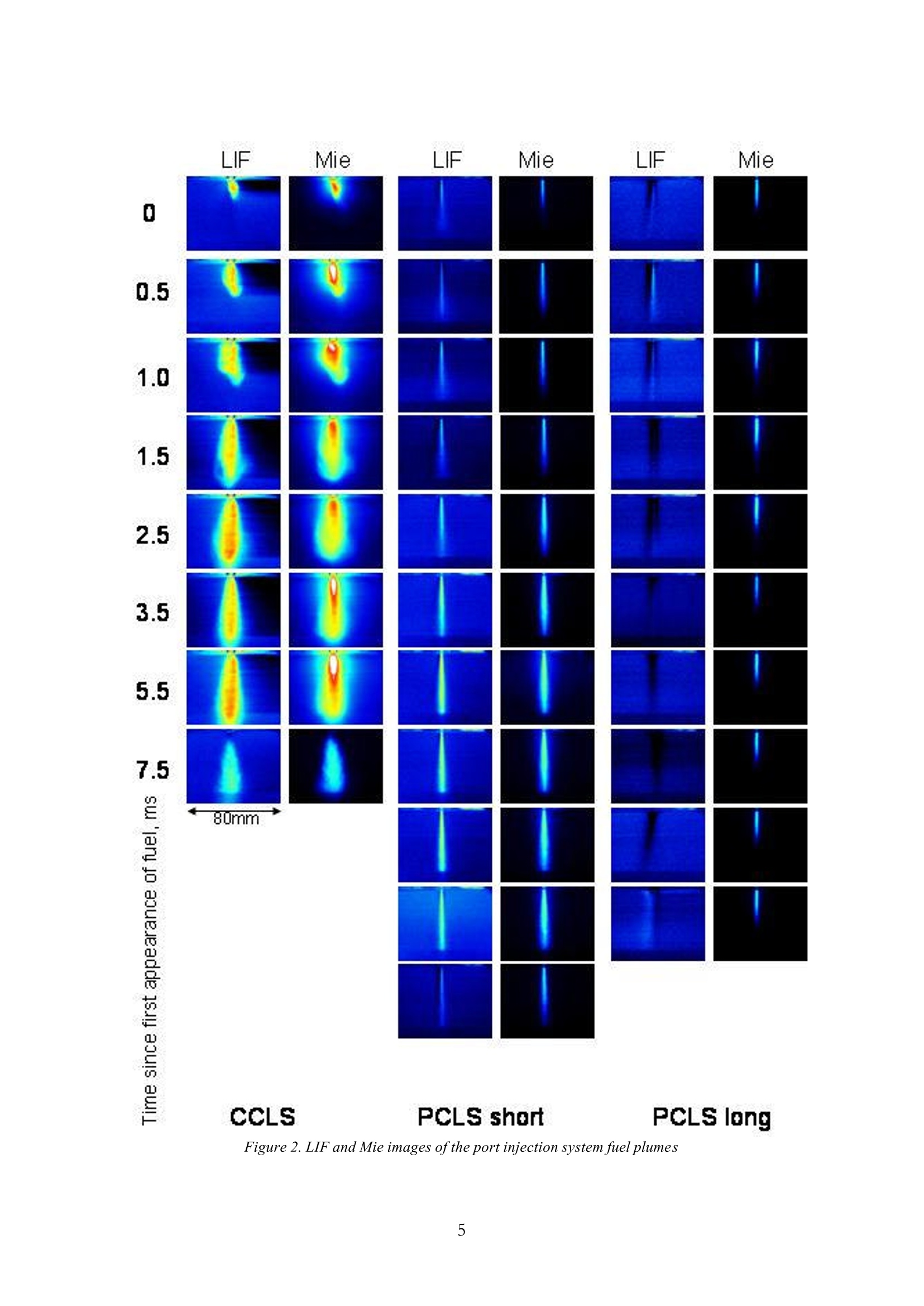
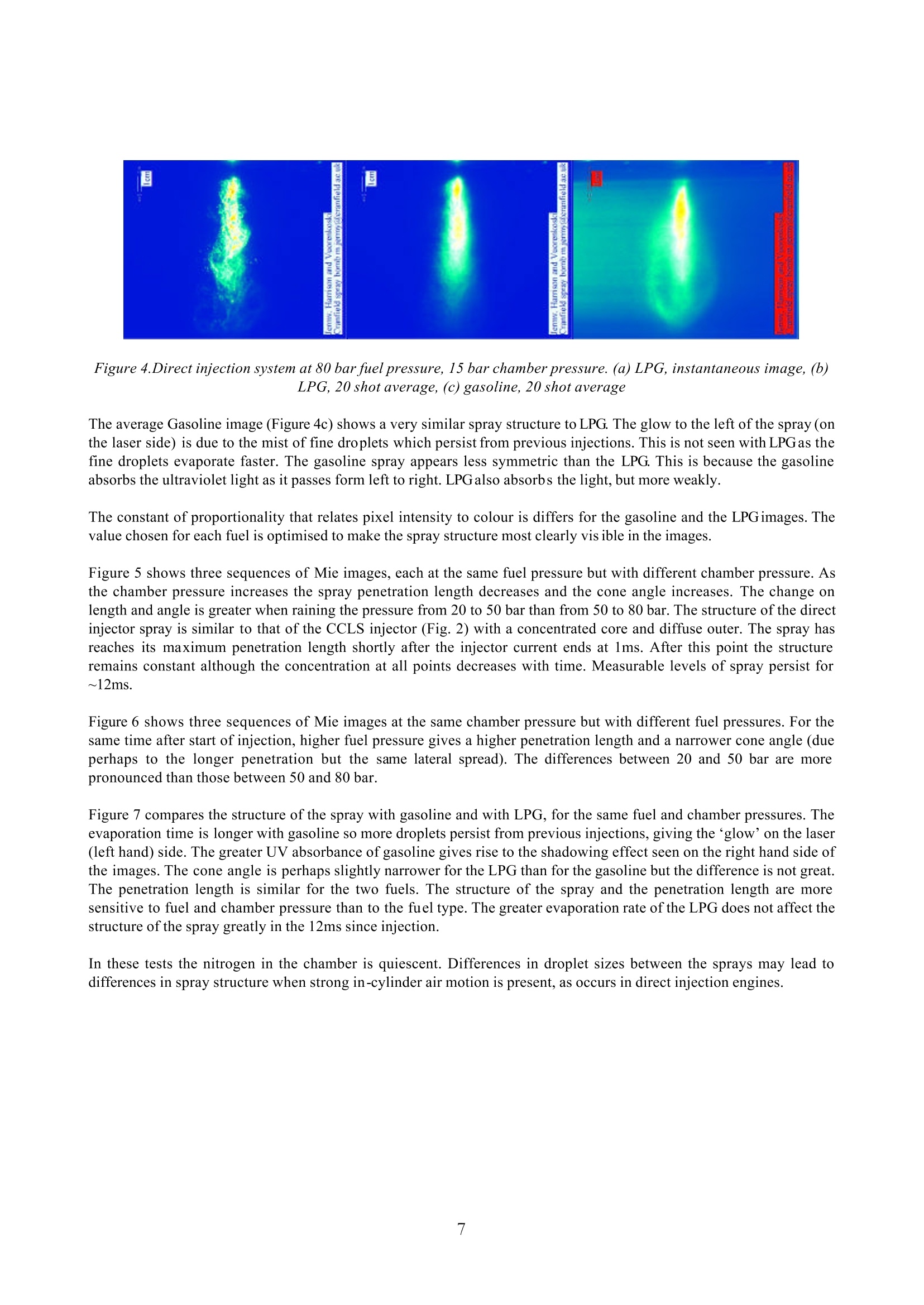
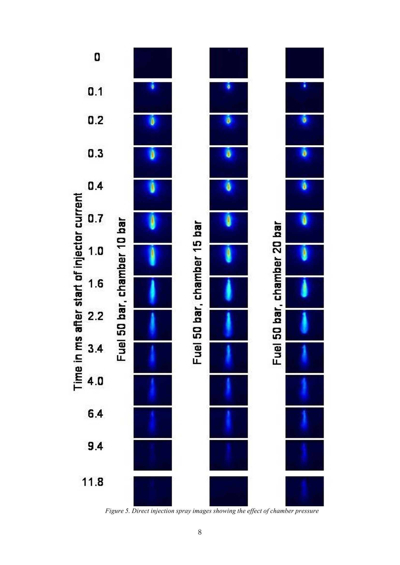
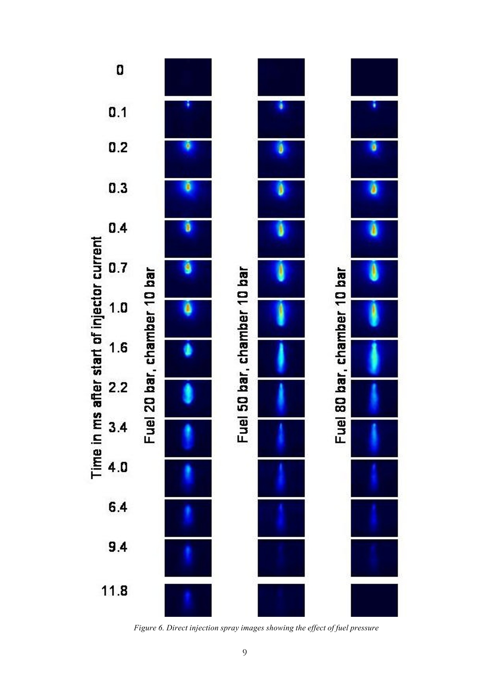
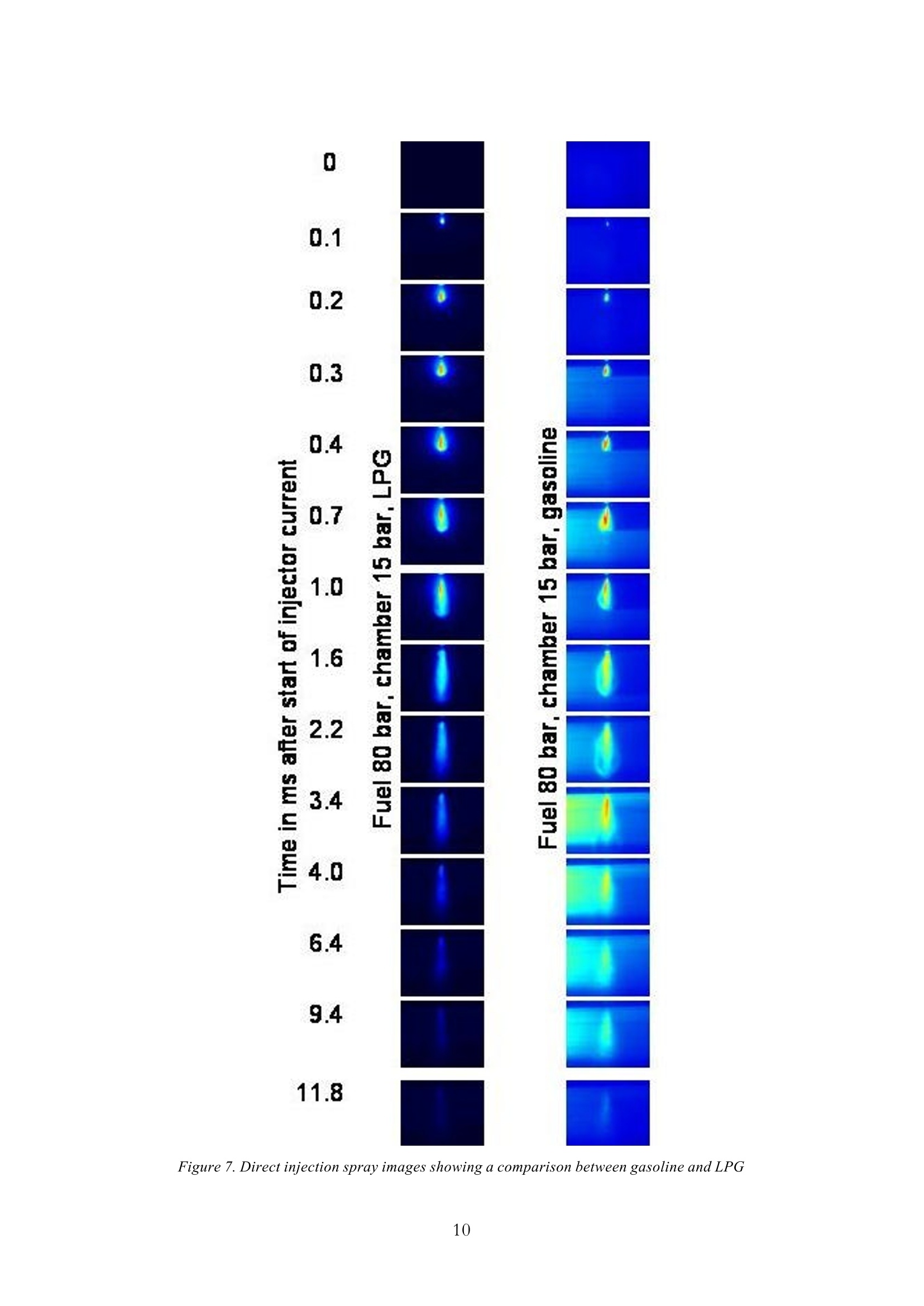
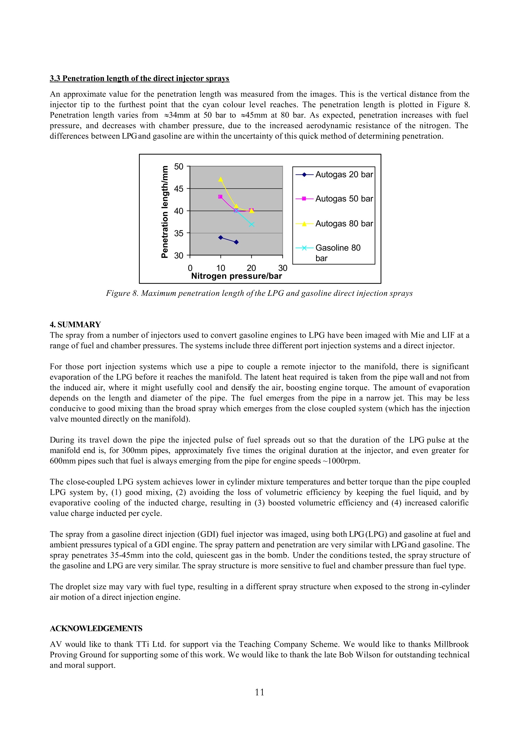
The structure of propane/LPG sprays from automotive fuel injectors as a function of fuel andambient pressure by Mie and LIFimaging by M.C. Jermy(), A.K. Vuorenkoski, T.I. Mohamed,E. Kaparis, M. Harrisonand M. Macartney(2) ()DAMSE,School of EngineeringCranfield University Cranfield Beds MK43 0AL United Kingdom http://www.cranfield.ac.uk/soe/departments/optical.htm E-Mail: m.jermy@cranfield.ac.uk (2)Jaymic Ltd, www.jaymic.co.uk ABSTRACT When a gasoline engine is converted to propane (LPG,Autogas) there is usually a reduction in power. This loss can bemitigated by careful design of the injection system such that the heat required for evaporation of the LPG is drawn fromthe intake air and not the intake walls. The air is cooled and densified, resulting in an increase in volumetric efficiency.To do this effectively requires the injector spray pattern to be known. There are many studies on the structure ofgasoline sprays, but few of LPGsprays. In this work we have imaged LPG sprays from a gasoline direct injection (GDI) injector, a port fuel injector, and from longand short pipes usually used to connect a remote LPG metering valve to the injection point in the manifold. Both Mieand LIF imaging have been used. For the LIF, acetone is added to the LPG. Images were taken in an optically accessedpressure chamber at pressures from atmospheric to 20 bar and with fuel line pressures from 10 to 80 bar. The imaging of the pipe-coupled injection system shows that (1) there is significant but not complete evaporation in thepipe, the amount of evaporation depending on the length and diameter of the pipe, and (2) during its travel down thepipe the injected pulse of fuel spreads out so that the duration of the LPG pulse at the manifold end is, for 300mm pipes,five times the original duration at the injector, and even greater for 600mm pipes such that fuel is always emerging fromthe pipe. When fuel evaporated in the pipe the latent heat required is taken from the pipe wall and not from the inducedair, where it might usefully cool and densify the air, boosting engine torque. The fuel emerges from the pipe in a narrowjet. This may be less conducive to good mixing than the broad spray which emerges from the close coupled system(which has the injection valve mounted directly on the manifold. The structure of the sprays and the amount of evaporation that occurs before the fuel enters the manifold explains theobserved differences in engine torque and in-cylinder mixture temperature observed with the different systems. The spray structure of the direct injector is similar with gasoline and LPG. The spray structure is more sensitive tcchanges in fuel or chamber pressure than to the type of fuel. The droplet size may vary with fuel type, resulting in adifferent spray structure when exposed to the strong in-cylinder air motion of a direct injection engine. 1.INTRODUCTION LPG (propane, Autogas) is of interest as a low cost, low pollutant emissions altemnative fuel for cars and trucks. LPG iscleaner than gasoline in that it tends to produce less particulates, carbon monoxide (CO) and unburnt hydrocarbons(UHC) (Poulton, 1994, Sher, 1998). Gasoline engines have been converted to LPG for 40 years, initially with simpleVenturi type LPG vapour-air mixing devices but recently with more sophisticated systems including sequential injectionof liquid LPG in the intake port, and direct injection of liquid LPG into the cylinder. Many conversion systems areavailable but most cause a significant (~10%) reduction in torque relative to the original gasoline or Diesel engine(Watson and Milkins 1982, Caton et al. 1997, Shehata 2001). In some cases this means the engine is no longer fit forpurpose, in others the engine will function but the loss of driveability discourages the driver from converting the engine.This loss can be mitigated by careful design of the injection system. If the heat required for evaporation of the LPG isdrawn from the intake air and not the intake walls, the air is cooled and densified, resulting in an increase in volumetricefficiency and~6% increase in power (Jermy et al.2004). As with gasoline it is also important to achieve good fuel-air mixing. There are many studies on the structure of gasolinesprays, but few of LPGsprays. In this work we have imaged LPG sprays from a gasoline direct injection (GDI) injector, a port fuel injector, and from longand short pipes usually used to connect a remote LPG metering valve to the injection point in the manifold. Both Mieand LIF imaging have been used. For the LIF, acetone is added to the LPG. Imaged were taken in an optically accessedpressure chamber at pressures from atmospheric to 20 bar and with fuel line pressures from 10 to 80 bar. Measurements of engine torque and in-cylinder mixture temperatures in a gasoline engines converted to LPG with eachof the three port injection systems are discussed in terms of the spray structure. 2.EXPERIMENTAL METHOD and PROCEDURES 2.1 Iniection systems The port injection LPG systems are sequential port injection systems with one LPG injector for each cylinder, an exhaustoxygen (lambda) sensor and closed loop control of the injection duration. One LPG system (hereafter called the ‘closecoupled LPG system’or CCLS) has the injectors mounted directly on the intake manifold, within 100mm of the inlet valve.The second LPG system (hereafter called the ‘pipe coupled LPG system’or PCLS) was the identical to the CCLS but thatthe injectors were not mounted directly on the manifold. Instead they were connected to the manifold by flexible hoses2mm in diameter. The pipes were used so the injectors could be mounted in a more convenient place. The connection onthe manifold was in the same place as the CCLS. These systems have been installed as both mono-fuel systems and bi-fuel systems capable of switching rapidly betweengasoline and LPG and have operated successfully on a 1.0 litre gasoline Nissan Micra engine (Jermy et al. 2004). Like allsequential closed loop systems they gives good transient response and a balanced, near stochiometric air fuel ratic(AFR) over all cylinders resulting in low pollutant emissions. The LPG is kept liquefied until the injector tip. Since the fuel is injected as a liquid, and evaporates only partially in themanifold, the system gives better volumetric efficiency than a gas injection system. There is an additional benefit fromcharge cooling. The liquid partly vaporises in the manifold and the vapour expands. Some of the energy required for thelatent heat of vaporisation and the PdV work of expansion is supplied by the inducted air (Jermy et al. 2004).Consequently this air is cooled, the mixture density increases and the mass of mixture (and hence total heating value ofthe mixture) inducted per cycle increases, hence the engine torque increases. A secondary benefit is that knock is lesslikely in the cooler mixture so the spark can be advanced further, increasing torque. The spark advance due to coolingadds to the advance due to the higher RON of LPG relative to gasoline (Watson and Milkins 1982, Caton et al. 1997,Shehata 2001). The LPG direct injection system is designed to mimic a system which might be used for injection of the LPG direct intothe cylinder of a gasoline direct injection engine, combining the high cycle efficiency of the direct injection engine withthe low pollutant emissions of the LPG fuel. It consists of a gasoline direct injection injector and solenoid driver,connected to a reservoir of LPG pressurised with a nitrogen bottle. A dip tube ensures that only liquid fuel form the bottom of the vessel reaches the injector. The injector was given a current pulse of 1ms total duration from a peak andhold driver. The peak current was 9A and the hold current 3.5A. The measurements were repeated with commercial gasoline to compare the spray patterns of the two fuels. The fuels were BP LPG or Total unleaded gasoline bought at UK filling stations. UK LPG is typically 96% LPG and meetsBS4250:1997. 2.2 Test rig The injector (or pipe) was mounted in the Cranfield sprays bomb (Fig. 1),a pressure chamber rated to 25bar with goodoptical access for measurements of fuel injectors. For the port injection system measurements, the chamber was kept at atmospheric pressure and purged periodically toclear the accumulated fuel. Fuel pressure was 15 bar and injection duration was 5 ms. For the direct injection system, the bomb was pressurised to 10, 15 or 20 bar and purged periodically. The nitrogentemperature was 20℃. The fuel pressure was set to 20, 50 or 80 bar. The injector current pulse lasted 1ms.Only Mieimages were taken. Figure 1. Cranfield 25 bar optically accessed sprays bomb 2.2 Imaging system The plume of fuel emerging from the injector valve (in the case of the direct injection and close coupled systems) or theend of the 2mm diameter pipe (in the case of the pipe coupled systems) was imaged. The plume was illuminated with a 45-60mm high,0.5mm thick light sheet from the fourth harmonic (266nm) of a Spectra Physics GCR Nd:YAG laser with 100-200mJ/pulse. The plume was imaged with a LaVision SprayMaster 3 camera with image intensifier and 105mm Nikkor UVlens. Two sets of images were taken. Laser Induced Fluorescence (LIF) images were taken of fluorescence emitted a by 8- 10 vol% acetone mixed with the LPG using a Schott WG360 filter. Mie-scatter images were taken without a filter. The LIFis emitted by both droplets and vapour and the signal is proportional to the local mass concentration of fuel independentof physical state. The Mie scatter is only caused by droplets, so the Mie images show the location of the liquid fuel. TheMie signal is proportional to the total droplet surface area in a region. For the port injection systems (CCLS and PCLS), images were taken at 7-10 different times after the start of the injectorcurrent pulse. At each time, 20 images were taken from successive cycles. For the direction injection system, the laser pulse energy was ~100mJ for LPG and ~200mJ for gasoline. The camerasettings were f/8, intensifier gate 200ns, intensifier gain 60, camera gain 95. Images were taken at 14 different times afterthe start of injector current. 20 images were taken at each time setting, from subsequent injection events. For all systems the images were averaged and corrected for background intensity and light sheet intensity variationswith LaVision DaVis 6.2 software. 3. RESULTS AND DISCUSSION 3.1 Port injection systems The images of the fuel plumes from the port injection systems are shown in Fig. 2. The images are on a false colour scalewith hot colours (red, orange, yellow) indicating high intensity i.e. high droplet concentrations and cold (green, blue)indicating low intensity. Note the time of the image is since the first appearance of fuel rather than since beginning ofinjector current. The PCLS systems have a transport delay between injector opening and fuel appearing at the end of thepipe. The close coupled injector shows a wide plume of fuel emerging fromthe injector valve and mixing with the surroundingair. The structure of the LIF and Mie images differs, with the Mie showing a bright central core, and the LIF showing amore even intensity profile. This indicates that the central core contains many droplets, which evaporate as they reachthe tip and edges of the plume. The pipe coupled injectors show a narrow jet of fuel. The Mie and LIF images have similar structure indicating that thedistribution of droplets more even than for the close coupled injector. The Mie images are much weaker for both pipecoupled injectors, indicating that the number of droplets remaining at the end of the pipe is much lower than the numberemerging from the injection valve: much of the liquid has evaporated in the pipe. The dark region on the centre of thePCLS long LIF images is due to imperfect background subtraction. During its travel down the pipe the injected pulse of fuel spreads out so that the duration of the LPG pulse at themanifold end is, for 300mm pipes, approximately five times the original duration at the injector, and even greater for600mm pipes such that fuel is always emerging from the pipe for engine speeds ~1000rpm. The structure of the CCLS fuel plume changes significantly with time over the first 1.5ms. In contrast after a 0.5ms periodduring which the basic structure is established, he structure of the jet from the pipe coupled injectors remainsapproximately constant with time, although the amount of fuel increases and decreases. The concentration along thecentreline is not a good fit to the Kleinstein theory for the structure of compressible free jets (Kleinstein, 1964) perhapsbecause the jet still contains significant mass of droplets whose dynamics differ from that of the gas. The constant of proportionality relating pixel intensity to colour is chosen for each injector and image type (Mie or LIF)to best display the structure of the image. However the constant is the same for all three sets of Mie images. The PCLSlong Mie images are weaker than those of the PCLS short indicating that the longer pipe leads to more evaporation of thefuel before it emerges. The wide plume of the close coupled injector suggests that in the engine manifold it will achieve much earlier and morecomplete mixing of the fuel and air than the pipe coupled system. The lack of liquid fuel in the plume of the pipe-coupledsystem suggests that much of the fuel has evaporated, leading to low volumetric efficiency due to the space occupiedby the vapour state fuel and due to the lack of liquid left to generate charge cooling. This vapourisation in the pipe alsoleads to a longer period during which fuel emerges from the pipe which can affect mixing. LIF Mie LIF Mie LIF Mie Mie 5 The pipe configuration affects the engine torque. Fig. 3 shows the torque measured at 3000 rpm, wide open throttle withclose-coupled injectors, and with pipe-coupled injectors with pipes of length 600 and 300mm length, and 2 and 4mmdiameter (Jermy et al. 2004). The figure clearly shows the torque advantage of close coupled injectors. It also shows thatthe pipe diameter is more important than pipe length. The smaller diameter the pipe, the better the torque, due to thesmaller surface area for heat transfer and to the increased velocity of the fuel, leaving less time for heat transfer andvaporisation in the pipe. The shorter the pipe the better the torque. Figure 3. Engine torque with differentpipe configurations To investigate the degree of cooling, the temperature of the mixture in cylinder 1 was measured with a 13um wire diametertype K thermocouple inserted through a dummy spark plug at 2000rpm (Jermy et al. 2004). The engine was run on theother three cylinders: there was no combustion in cylinder 1. The temperature was logged with a LabView system andthe minimum temperature reached in each cycle captured,and averaged over ten cycles. The measurement was repeatedwith injection on cylinder 1 switched off to give the temperature of a pure air charge without any cooling due to fuelvaporisation. The difference between the minimum cycle temperatures with and without injection is caused by thevaporisation and expansion cooling of the fuel and is given in Table 1. The presence of the fuel causes a 14K drop in temperature for the close coupled LPG system due to the evaporation ofthe LPG. For gasoline the temperature drop is similar, as the gasoline also vaporises. The pipe-coupled LPG systemhowever gains the energy required for vaporisation through the pipe walls rather than from the inducted air: this resultsin a much smaller 5K drop in mixture temperature. A simple model of the effect of charge cooling on torque predicted the improvement in torque due to close coupling ofthe injectors to within 1%, suggesting that charge cooling is the principal mechanism behind the torque advantage ofclose over pipe coupling (Jermy et al. 2004). CCLS PCLS Gasoline -14.3 士 2.4K-4.9 士 2.4K-13.0 2.2K Table 1.Mixture temperature variations in cylinder with different pipe configurations 3.2 Direct iniection svstem Fig. 4a-c shows three individual Mie images for comparison. All are taken with fuel at 80 bar, nitrogen in bomb at 15 barand are at 2.2ms after the injector current begins. The instantaneous image of LPG(Figure 4a) shows the turbulent mixingof the spray with the surrounding gas. The vortices are not visible in the average LPG image (Figure 4b)as they varyfrom shot to shot and are averaged away. To scale the image, the ellipse in the top left corner is 1cm long and its top is level with the injector tip. Figure 4.Direct injection system at 80 bar fuel pressure, 15 bar chamber pressure. (a) LPG, instantaneous image, (b)LPG, 20 shot average, (c) gasoline, 20 shot average The average Gasoline image (Figure 4c) shows a very similar spray structure to LPG. The glow to the left of the spray (onthe laser side) is due to the mist of fine droplets which persist from previous injections. This is not seen with LPG as thefine droplets evaporate faster. The gasoline spray appears less symmetric than the LPG. This is because the gasolineabsorbs the ultraviolet light as it passes form left to right. LPG also absorbs the light, but more weakly. The constant of proportionality that relates pixel intensity to colour is differs for the gasoline and the LPGimages. Thevalue chosen for each fuel is optimised to make the spray structure most clearly vis ible in the images. Figure 5 shows three sequences of Mie images, each at the same fuel pressure but with different chamber pressure. Asthe chamber pressure increases the spray penetration length decreases and the cone angle increases. The change onlength and angle is greater when raining the pressure from 20 to 50 bar than from 50 to 80 bar. The structure of the directinjector spray is similar to that of the CCLS injector (Fig. 2) with a concentrated core and diffuse outer. The spray hasreaches its maximum penetration length shortly after the injector current ends at 1ms. After this point the structureremains constant although the concentration at all points decreases with time. Measurable levels of spray persist for~12ms. Figure 6 shows three sequences of Mie images at the same chamber pressure but with different fuel pressures. For thesame time after start of injection, higher fuel pressure gives a higher penetration length and a narrower cone angle (dueperhaps to the longer penetration but the same lateral spread). The differences between 20 and 50 bar are morepronounced than those between 50 and 80 bar. Figure 7 compares the structure of the spray with gasoline and with LPG, for the same fuel and chamber pressures. Theevaporation time is longer with gasoline so more droplets persist from previous injections, giving the ‘glow’on the laser(left hand) side. The greater UV absorbance of gasoline gives rise to the shadowing effect seen on the right hand side ofthe images. The cone angle is perhaps slightly narrower for the LPG than for the gasoline but the difference is not great.The penetration length is similar for the two fuels. The structure of the spray and the penetration length are moresensitive to fuel and chamber pressure than to the fuel type. The greater evaporation rate of the LPG does not affect thestructure of the spray greatly in the 12ms since injection. In these tests the nitrogen in the chamber is quiescent. Differences in droplet sizes between the sprays may lead todifferences in spray structure when strong in-cylinder air motion is present, as occurs in direct injection engines. Time in ms after start of injector current nenFuel 50 bar, chamber 10 barncn nsn Fuel 50 bar, chamber 15 bar Fuel 50 bar, chamber 20 bar Time in ms after start of injector current Fuel 20 bar, chamber 10 bar -- Fuel 50 bar. chamber 10 bar Fuel 80 bar, chamber 10 bar Time in ms after start of injector current Fuel 80 bar, chamber 15 bar, gasoline 3.3 Penetration length of the direct injector sprays An approximate value for the penetration length was measured from the images. This is the vertical distance from theinjector tip to the furthest point that the cyan colour level reaches. The penetration length is plotted in Figure 8.Penetration length varies from ~34mm at 50 bar to ~45mm at 80 bar. As expected, penetration increases with fuelpressure, and decreases with chamber pressure, due to the increased aerodynamic resistance of the nitrogen. Thedifferences between LPGand gasoline are within the uncertainty of this quick method of determining penetration. Figure 8. Maximum penetration length ofthe LPG and gasoline direct injection sprays 4.SUMMARY The spray from a number of injectors used to convert gasoline engines to LPG have been imaged with Mie and LIF at arange of fuel and chamber pressures. The systems include three different port injection systems and a direct injector. For those port injection systems which use a pipe to couple a remote injector to the manifold, there is significantevaporation of the LPG before it reaches the manifold. The latent heat required is taken from the pipe wall and not fromthe induced air, where it might usefully cool and densify the air, boosting engine torque. The amount of evaporationdepends on the length and diameter of the pipe. The fuel emerges from the pipe in a narrow jet. This may be lessconducive to good mixing than the broad spray which emerges from the close coupled system (which has the injectionvalve mounted directly on the manifold). During its travel down the pipe the injected pulse of fuel spreads out so that the duration of the LPG pulse at themanifold end is, for 300mm pipes, approximately five times the original duration at the injector, and even greater for600mm pipes such that fuel is always emerging from the pipe for engine speeds ~1000rpm. The close-coupled LPG system achieves lower in cylinder mixture temperatures and better torque than the pipe coupledLPG system by, (1) good mixing, (2) avoiding the loss of volumetric efficiency by keeping the fuel liquid, and byevaporative cooling of the inducted charge, resulting in (3) boosted volumetric efficiency and (4) increased calorificvalue charge inducted per cycle. The spray from a gasoline direct injection (GDI) fuel injector was imaged, using both LPG(LPG) and gasoline at fuel andambient pressures typical of a GDI engine. The spray pattern and penetration are very similar with LPG and gasoline. Thespray penetrates 35-45mm into the cold, quiescent gas in the bomb. Under the conditions tested, the spray structure ofthe gasoline and LPG are very similar. The spray structure is more sensitive to fuel and chamber pressure than fuel type. The droplet size may vary with fuel type, resulting in a different spray structure when exposed to the strong in-cylinderair motion of a direct injection engine. ACKNOWLEDGEMENTS AV would like to thank TTi Ltd. for support via the Teaching Company Scheme. We would like to thanks MillbrookProving Ground for supporting some of this work. We would like to thank the late Bob Wilson for outstanding technicaland moral support. REFERENCES Caton J.A., Mcdermott M. and Chona R. (1997),“Development of a Dedicated LPG-Fueled, Spark-Ignition Engine andVehicle for the 1996 LPG Vehicle Challenge”SAE paper no. 972692 Jermy M.C., Harrison M., Vuorenkoski A.K., Mohamad T.I., Kaparis E. and Macartney M.,“Overcoming power loss inLPG/LPG conversions of vehicle engines”, sub. to Int. J. Vehicle Design 2004 Kleinstein G. (1964),“Mixing in turbulent axially symmetric free jets”, J. Spacecraft Vol.1 403-408 Poulton M.L. (1994), “Alternative fuels for road vehicles”, Computational Mechanics Publications, Southampton Shehata M.S. (2001),“Combustioncharacteristics ofspark ignition engine fuelled by LPG”ASME Internal Combustion Engine Division (Publication) ICE, Vol.37 147-156 Sher E. (1998),“Handbook of air pollution from internal combustion engines”, Academic Press Watson H.C., Milkins E.E.(1982),“Comparison and optimization of emission efficiency and power of five automotivefuels in one engine”, Int. J.Vehicle Design Vol 3, 463-476 ( Jermy M.C., Harrison M ., Vuorenkoski A.K., Mohamad T.I., K a paris E . and M a cartney M.,“Overcoming powe r loss inLPG/LPGconversions of vehicle engines”, sub. To Int. J. Vehicle Design 2004 mi ) When a gasoline engine is converted to propane (LPG, Autogas) there is usually a reduction in power. This loss can bemitigated by careful design of the injection system such that the heat required for evaporation of the LPG is drawn fromthe intake air and not the intake walls. The air is cooled and densified, resulting in an increase in volumetric efficiency.To do this effectively requires the injector spray pattern to be known. There are many studies on the structure ofgasoline sprays, but few of LPG sprays.In this work we have imaged LPG sprays from a gasoline direct injection (GDI) injector, a port fuel injector, and from longand short pipes usually used to connect a remote LPG metering valve to the injection point in the manifold. Both Mieand LIF imaging have been used. For the LIF, acetone is added to the LPG. Images were taken in an optically accessedpressure chamber at pressures from atmospheric to 20 bar and with fuel line pressures from 10 to 80 bar.The imaging of the pipe-coupled injection system shows that (1) there is significant but not complete evaporation in thepipe, the amount of evaporation depending on the length and diameter of the pipe, and (2) during its travel down thepipe the injected pulse of fuel spreads out so that the duration of the LPG pulse at the manifold end is, for 300mm pipes,five times the original duration at the injector, and even greater for 600mm pipes such that fuel is always emerging fromthe pipe. When fuel evaporated in the pipe the latent heat required is taken from the pipe wall and not from the inducedair, where it might usefully cool and densify the air, boosting engine torque. The fuel emerges from the pipe in a narrowjet. This may be less conducive to good mixing than the broad spray which emerges from the close coupled system(which has the injection valve mounted directly on the manifold.The structure of the sprays and the amount of evaporation that occurs before the fuel enters the manifold explains theobserved differences in engine torque and in-cylinder mixture temperature observed with the different systems.The spray structure of the direct injector is similar with gasoline and LPG. The spray structure is more sensitive tochanges in fuel or chamber pressure than to the type of fuel. The droplet size may vary with fuel type, resulting in adifferent spray structure when exposed to the strong in-cylinder air motion of a direct injection engine.
确定


还剩10页未读,是否继续阅读?

产品配置单


北京欧兰科技发展有限公司为您提供《汽车燃料喷嘴产生的丙烷/液化石油气中喷雾结构与燃料和环境压力的关系检测方案(激光粒度仪)》,该方案主要用于汽车排放与节能中理化分析检测,参考标准--,《汽车燃料喷嘴产生的丙烷/液化石油气中喷雾结构与燃料和环境压力的关系检测方案(激光粒度仪)》用到的仪器有LaVision SprayMaster 喷雾成像测量系统、PLIF平面激光诱导荧光火焰燃烧检测系统、德国LaVision PIV/PLIF粒子成像测速场仪、LaVision HighSpeedStar 高帧频相机、汽车发动机多参量测试系统
推荐专场


该厂商其他方案
更多