


方案详情
文
活化表面的方法很多,它们都是为了提高表面自由能。通过比较测试油墨和接触角测量发现,测试油墨很多时候会产生问题,特别是在考虑极性和色散力组成部分时。
方案详情

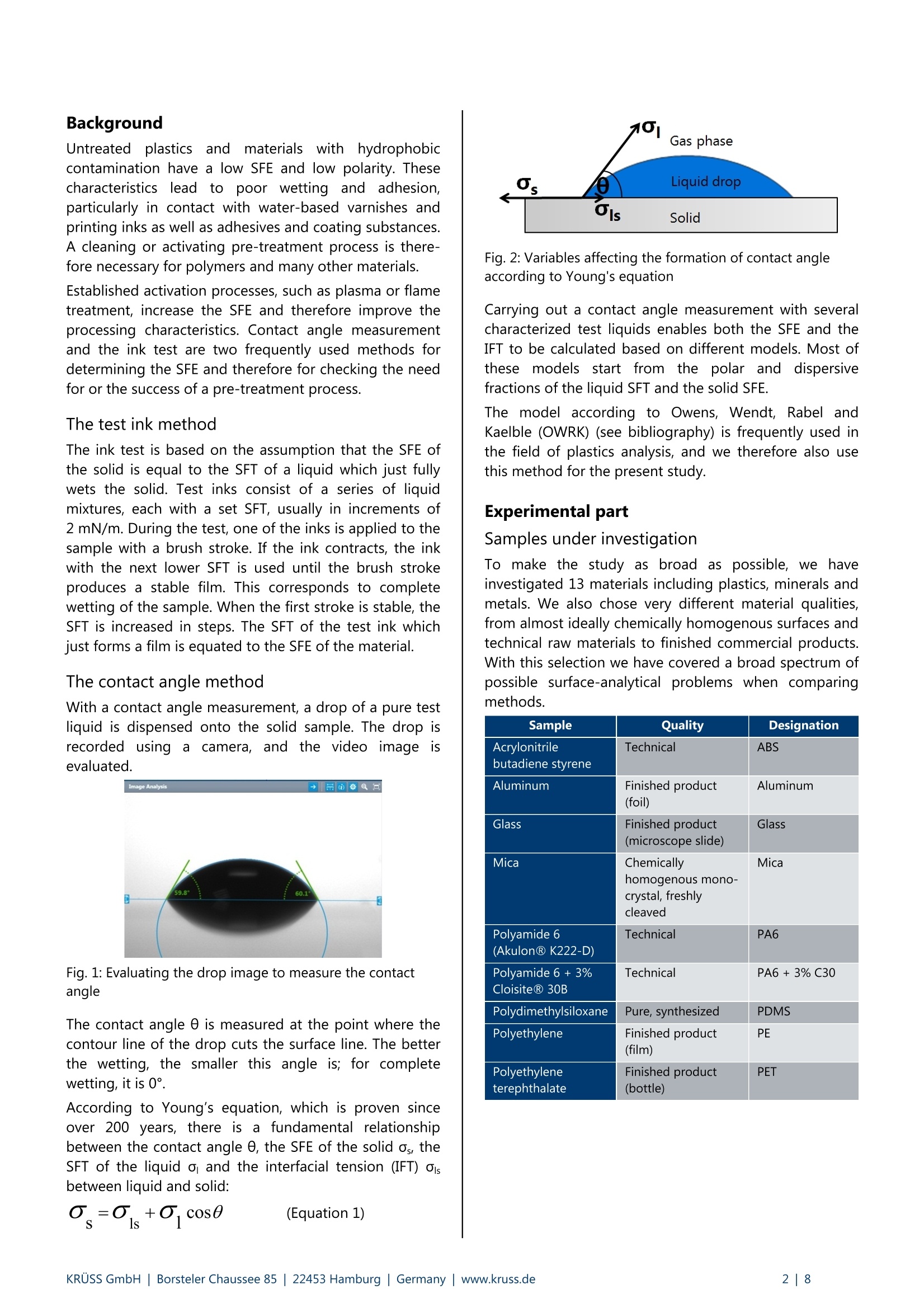
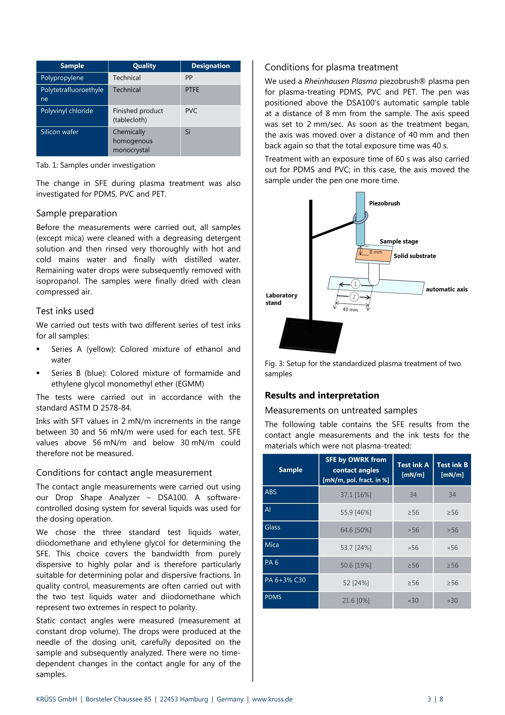
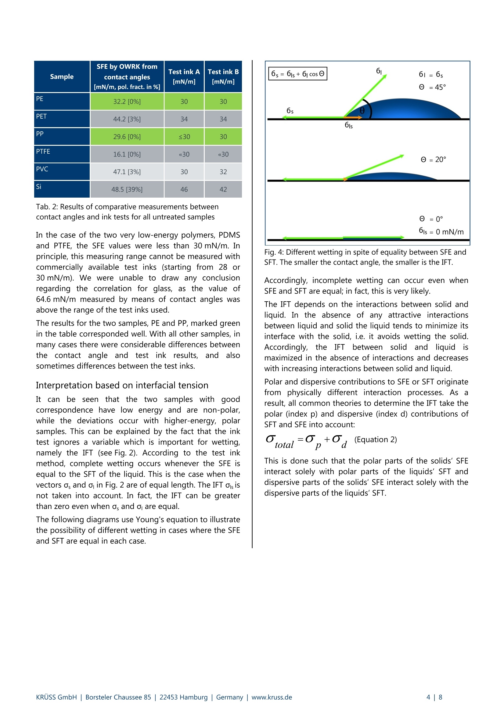
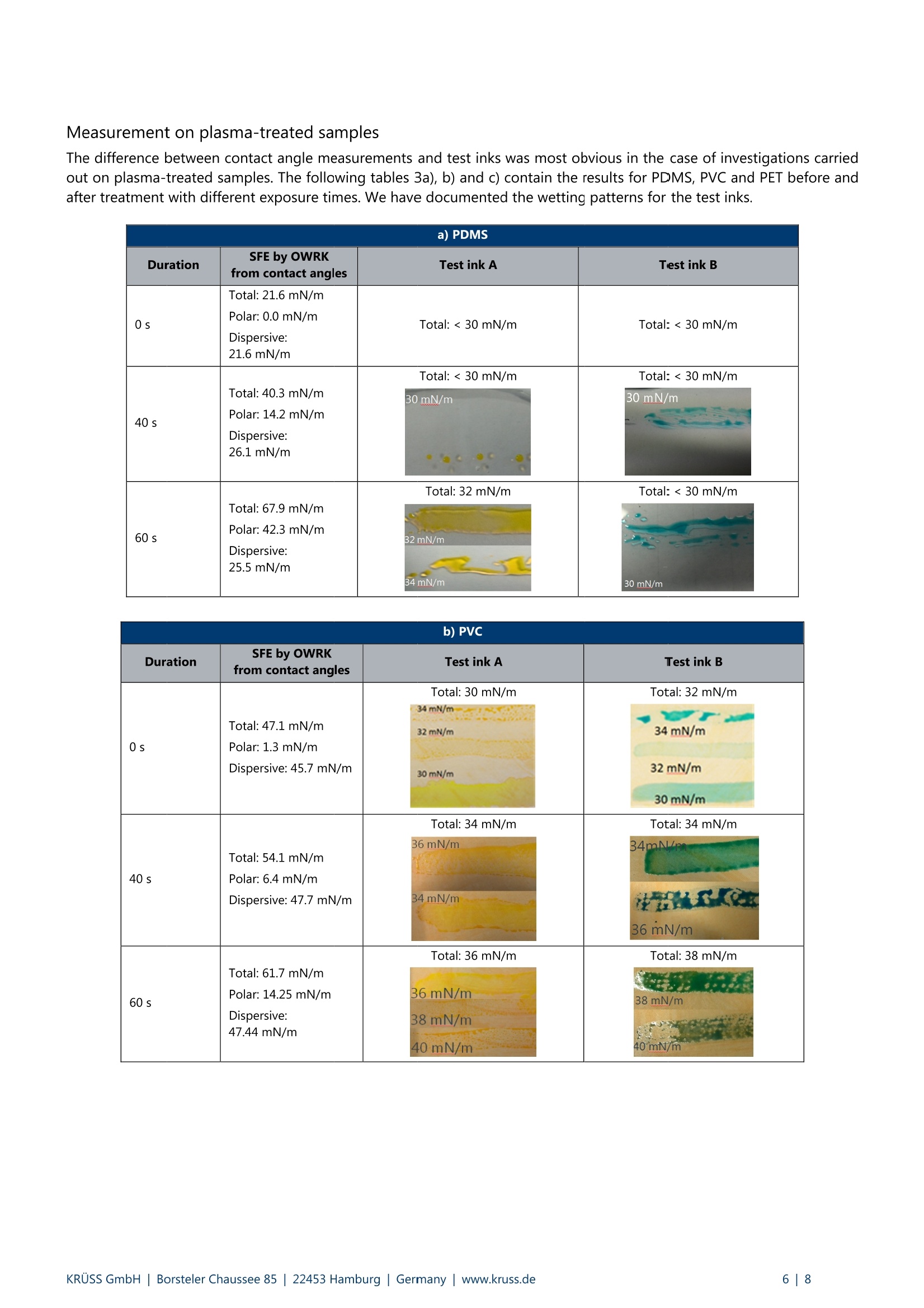
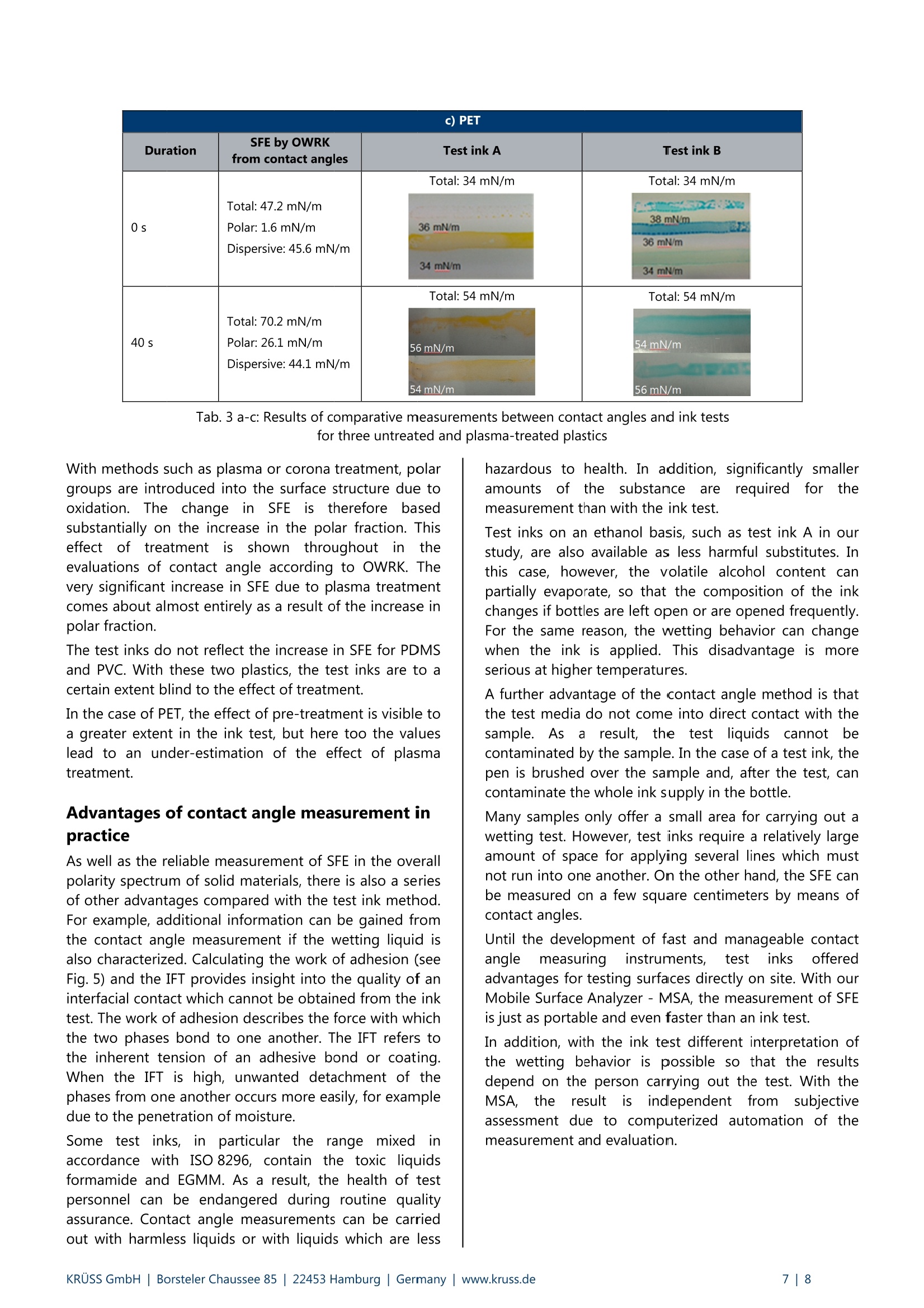
KRUSS Application Report Application report: AR 272 Industry section: Surface Treatment for Polymers Author: TW, MJI Date: 06/2014 Method: SFE Mobile Surface Analyzer- Drop Shape Analyzer- AAE MSA DSA100 Keywords: contact angle, surface free energy, surface treatment, surface cleaning Why test inks cannot tell the full truth about surface free energy A comparative study between test inks and contact angle measurements in our laboratory There are a range of methods for activating the surface when treating materials before coating, bonding or printing.These include thermal or electrical methods, such as plasma, flame or corona treatment, and chemical treatment withoxidizing gases. Equally important are cleaning steps which remove hydrophobic substances from the surface. All thesemethods increase the surface free energy (SFE) and therefore improve wettability and adhesion. Norms such as DIN 55660 for coating materials and DIN EN 828 for adhesive processes specify contact anglemeasurement as the method for determining the SFE of surfaces and for checking an activating or cleaning pre-treatmentprocess. In addition, test inks, which are intended to reflect the SFE based on liquids with set surface tension (SFT), arealso frequently used. According to the ink test method, complete wetting always occurs when the values of the SFE of the solid and the SFT ofthe liquid are equal. Many scientific authors have refuted this wetting theory and have shown that only an analysis of thepolar and dispersive interaction fractions of the SFE and the SFT provide a complete picture of the wetting process.Contact angle measurements, which take these interactions into account, and ink tests should accordingly lead todifferent evaluations of surfaces and therefore also to different assessments of the quality of a pre-treatment process. In the present study, we have compared SFE results from contact angle measurements with those from ink tests for 13very different materials. We also carried out comparative measurements on three plasma-treated plastics. Both the smallnumber of consistent results and the large number of deviations can be conclusively explained when we take the effect ofpolar and dispersive interactions into account. It appears that the SFE result of an ink test must be called into question formany samples. In this article, we also point out some advantages of the contact angle method in measurement practice. Background UntreatedplasticsandnmaterialsIswithrhydrophobiccontamination have a low SFE and low polarity. Thesecharacteristics lead to poor wetting and adhesion,particularly in contact with water-based varnishes andprinting inks as well as adhesives and coating substances.A cleaning or activating pre-treatment process is there-fore necessary for polymers and many other materials. Established activation processes, such as plasma or flametreatment, increase the SFE and therefore improve theprocessing characteristics. Contact angle measurementand the ink test are two frequently used methods fordetermining the SFE and therefore for checking the needfor or the success ofa pre-treatment process. The test ink method The ink test is based on the assumption that the SFE ofthe solid is equal to the SFT of a liquid which just fullywets the solid. Test inks consist of a series of liquidmixtures, each with a set SFT, usually in increments of2 mN/m. During the test, one of the inks is applied to thesample with a brush stroke. If the ink contracts, the inkwith the next lower SFT is used until the brush strokeproduces a stable film. This corresponds to completewetting of the sample. When the first stroke is stable, theSFT is increased in steps. The SFT of the test ink whichjust forms a film is equated to the SFE of the material. The contact angle method With a contact angle measurement, a drop of a pure testliquid is dispensed onto the solid sample. The drop isrecorded using a camera, and the video image isevaluated. Fig. 1: Evaluating the drop image to measure the contactangle The contact angle 0 is measured at the point where thecontour line of the drop cuts the surface line. The betterthe wetting, the smaller this angle is; for completewetting, it is 0°. According to Young's equation, which is proven sinceover 200 years, there is a fundamental relationshipbetween the contact angle e, the SFE of the solid o,, theSFT of the liquid o and the interfacial tension (IFT) oisbetween liquid and solid: Fig. 2: Variables affecting the formation of contact angleaccording to Young's equation Carrying out a contact angle measurement with severalcharacterized test liquids enables both the SFE and theIFT to be calculated based on different models. Most ofthese models start from the polar and dispersivefractions of the liquid SFT and the solid SFE. The model according to Owens, Wendt, Rabel andKaelble (OWRK) (see bibliography) is frequently used inthe field of plastics analysis, and we therefore also usethis method for the present study. Experimental part Samples under investigation To make the study as broad as possible, we haveinvestigated 13 materials including plastics, minerals andmetals. We also chose very different material qualities,from almost ideally chemically homogenous surfaces andtechnical raw materials to finished commercial products.With this selection we have covered a broad spectrum ofpossible surface-analytical problems when comparingmethods. Sample Quality Designation Acrylonitrilebutadiene styrene Technical ABS Aluminum Finished product(foil) Aluminum Glass Finished product (microscope slide) Glass Mica Chemically homogenous mono-crystal, freshly cleaved Mica Polyamide 6(AkulonQ K222-D) Technical PA6 Polyamide 6 +3%CloisiteR 30B Technical PA6+ 3% C30 Polydimethylsiloxane Pure, synthesized PDMS Polyethylene Finished product(film) PE Polyethyleneterephthalate Finished product(bottle) PET Sample Quality Designation Polypropylene Technical PP Polytetrafluoroethyle ne Technical PTFE Polyvinyl chloride Finished product(tablecloth) PVC Silicon wafer Chemically homogenous monocrystal Si Tab.1: Samples under investigation The change in SFE during plasma treatment was alsoinvestigated for PDMS, PVC and PET. Sample preparation Before the measurements were carried out, all samples(except mica) were cleaned with a degreasing detergentsolution and then rinsed very thoroughly with hot andcold mains water and finally with distilled water.Remaining water drops were subsequently removed withisopropanol. The samples were finally dried with cleancompressed air. Test inks used We carried out tests with two different series of test inksfor all samples: Series A (yellow): Colored mixture of ethanol andwater m Series B (blue): Colored mixture of formamide andethylene glycol monomethyl ether (EGMM) The tests were carried out in accordance with thestandard ASTM D 2578-84. Inks with SFT values in 2 mN/m increments in the rangebetween 30 and 56 mN/m were used for each test. SFEvalues above 56 mN/m and below 30mN/m couldtherefore not be measured. Conditions for contact angle measurement The contact angle measurements were carried out usingour DropShape Analyzer - IDSA100. A software-controlled dosing system for several liquids was used forthe dosing operation. We chose the three standardttest liquids water,diiodomethane and ethylene glycol for determining theSFE. This choice covers the bandwidth from purelydispersive to highly polar and is therefore particularlysuitable for determining polar and dispersive fractions. Inquality control, measurements are often carried out withthe two test liquids water and diiodomethane whichrepresent two extremes in respect to polarity. Static contact angles were measured (measurement atconstant drop volume). The drops were produced at theneedle of the dosing unit, carefully deposited on thesample and subsequently analyzed. There were no time-dependent changes in the contact angle for any of thesamples. We used a Rheinhausen Plasma piezobrushQ plasma penfor plasma-treating PDMS, PVC and PET. The pen waspositioned above the DSA100's automatic sample tableat a distance of 8 mm from the sample. The axis speedwas set to 2 mm/sec. As soon as the treatment began,the axis was moved over a distance of 40 mm and thenback again so that the total exposure time was 40 s. Treatment with an exposure time of 60 s was also carriedout for PDMS and PVC; in this case, the axis moved thesample under the pen one more time. Fig. 3: Setup for the standardized plasma treatment of twosamples Results and interpretation Measurements on untreated samples The following table contains the SFE results from thecontact angle measurements and the ink tests for thematerials which were not plasma-treated: Sample SFE by OWRK fromcontact angles[mN/m,pol. fract. in %] Test ink A[mN/m] Test ink B[mN/m] ABS 37.1[16%] 34 34 Al 55.9[46%] ≥56 ≥56 Glass 64.6[50%] >56 >56 Mica 53.7[24%] >56 》56 PA6 50.6[19%] ≥56 ≥56 PA 6+3% C30 52 [24%] ≥56 ≥56 PDMS 21.6[0%] 《30 《30 Sample SFE by OWRK fromcontact angles[mN/m, pol. fract. in %] Test ink A [mN/m] Test ink B [mN/m] PE 32.2[0%] 30 30 PET 44.2[3%] 34 34 PP 29.6[0%] ≤30 30 PTFE 16.1[0%] 《30 《30 PVC 47.1[3%] 30 32 Si 48.5[39%] 46 42 Tab. 2: Results of comparative measurements betweencontact angles and ink tests for all untreated samples In the case of the two very low-energy polymers, PDMSand PTFE, the SFE values were less than 30 mN/m. Inprinciple, this measuring range cannot be measured withcommercially available test inks (starting from 28 or30 mN/m). We were unable to draw any conclusionregarding the correlation for glass, as the value of64.6 mN/m measured by means of contact angles wasabove the range of the test inks used. The results for the two samples, PE and PP, marked greenin the table corresponded well. With all other samples, inmany cases there were considerable differences betweenthe contact angle andl test ink: results, and alsosometimes differences between the test inks. Interpretation based on interfacial tension It can be seen that the two samples with goodcorrespondence have low energy and are non-polar,while the deviations occur with higher-energy, polarsamples. This can be explained by the fact that the inktest ignores a variable which is important for wetting,namely the IFT (see Fig.2). According to the test inkmethod, complete wetting occurs whenever the SFE isequal to the SFT of the liquid. This is the case when thevectors os and o in Fig. 2 are of equal length. The IFT ois isnot taken into account. In fact, the IFT can be greaterthan zero even when as and o are equal. The following diagrams use Young's equation to illustratethe possibility of different wetting in cases where the SFEand SFT are equal in each case. Fig. 4: Different wetting in spite of equality between SFE andSFT. The smaller the contact angle, the smaller is the IFT. Accordingly, incomplete wetting can occur even whenSFE and SFT are equal; in fact, this is very likely. The IFT depends on the interactions between solid andliquid. In the absence of any attractive interactionsbetween liquid and solid the liquid tends to minimize itsinterface with the solid, i.e. it avoids wetting the solid.Accordingly, the IFT between solidandliquidismaximized in the absence of interactions and decreaseswith increasing interactions between solid and liquid. Polar and dispersive contributions to SFE or SFT originatefrom physically different interaction processes. Asaresult, all common theories to determine the IFT take thepolar (index p) and dispersive (index d) contributions ofSFT and SFE into account: This is done such that the polar parts of the solids’ SFEinteract solely with polar parts of the liquids' SFT anddispersive parts of the solids’ SFE interact solely with thedispersive parts of the liquids'SFT. The following figure illustrates this behavior. Fig. 5: Schematic diagram of the interactions for the contactbetween phases (top: complete wetting; bottom: incompletewetting). IFT and work of adhesion were calculatedaccording to OWRK The figure shows a liquid with a total SFT of 50 mN/mgetting into contact with a solid with an SFE of also50 mN/m. Thus, following the idea of test inks, the liquidshould wet the solid completely. The large hands represent the (often stronger) polarparts and the small hands the (often weaker) dispersiveparts of SFE and SFT, respectively. The upper panel showsa perfect match between the polar and dispersive parts:every polar hand of the solid grabs a polar hand of theliquid and every dispersive hand finds its dispersivepartner. The attracting interaction between solid andliquid is maximized and the interfacial tension vanishes.In this case of a vanishing interfacial tension, the contactangle becomes zero as illustrated in the lower panel ofFig. 4. However, in practice such a situation can indeedalmost exclusively be found if totally dispersive liquidsget in contact with totally dispersive solids. The lower panel of the figure shows the case in which thedistribution into polar and dispersive parts of SFE andSFT are different. In this example, there is only one pair oflarge polar hands and small dispersive hands grabbingeach other, respectively. As a consequence, there is aremaining interfacial tension in the liquid-solid bond.This remaining interfacial tension results inanon-vanishing contact angle as illustrated in the top andmiddle panel in Fig. 4. Despite SFE and SFT being equal,the liquid does not fully wet the solid as expected whenfollowing the test ink idea. This is exactly the case when atest ink is applied on a solid with a different degree ofpolarity. In another study we have determined the polar anddispersive parts of the test inks used for the presentwork. We found that the test inks with an SFT of30 mN/m are almost completely non-polar and that thepolarity increases with the SIFT value. Knowing that, it canbe understood why only for PP and PE the SFE valuesdetected with the test inks agree with that determinedwith contact angle measurements. For these samples, inaddition to SFE and OFS being equal, also the polaritiesare the same (polar part of 0 mN/m). Thus, according tothe wetting theories, the IFT vanishes and the test inksfully wet the solid, i.e. exhibit a contact angle of zerodegrees. For all other possible combinations of test inksand solids in which SFE and SFT are equal, the polaritiesare different so that the wetting test with the test inkscannot give the solid’s SFE. Moreover, the polarities forthe blue and yellow test inks having the same SFT valueare different. This explains why for example for Si eventhe SFEs determined with the two different test inks weredifferent. Measurement on plasma-treated samples The difference between contact angle measurements and test inks was most obvious in the case of investigations carriedout on plasma-treated samples. The following tables 3a), b) and c) contain the results for PDMS,PVC and PET before andafter treatment with different exposure times. We have documented the wetting patterns for the test inks a) PDMS Duration SFE by OWRK from contact angles Test ink A Test ink B 0s Total: 21.6mN/m Polar: 0.0 mN/mDispersive: 21.6 mN/m Total: <30 mN/m Total: <30 mN/m 40 s Total: 40.3 mN/m Polar: 14.2 mN/mDispersive: 26.1 mN/m Total:< 30 mN/m 30 mN/m Total:<30 mN/m 30mN/m 60s Total: 67.9 mN/mPolar: 42.3 mN/mDispersive:25.5 mN/m Total: 32 mN/m B2mN/m 34mN/m Total:<30 mN/m 一 30 mN/m With methods such as plasma or corona treatment, polargroups are introduced into the surface structure due tooxidation.The change inlSFEis therefore basedsubstantially on the increase in the polar fraction. Thiseffect oftreatment isshowntthroughoutiimntheevaluations of contact angle according to OWRK. Thevery significant increase in SFE due to plasma treatmentcomes about almost entirely as a result of the increase inpolar fraction. Tab. 3 a-c: Results of comparative measurements between contact angles and ink testsfor three untreated and plasma-treated plasticsKRUSS GmbH|Borsteler Chaussee 85|22453 Hamburg| Germany|www.kruss.de The test inks do not reflect the increase in SFE for PDMSand PVC. With these two plastics, the test inks are to acertain extent blind to the effect of treatment. In the case of PET, the effect of pre-treatment is visible toa greater extent in the ink test, but here too the valueslead to an under-estimation of the effect of plasmatreatment. Advantages of contact angle measurement inpractice As well as the reliable measurement of SFE in the overallpolarity spectrum of solid materials, there is also a seriesof other advantages compared with the test ink method.For example, additional information can be gained fromthe contact angle measurement if the wetting liquid isalso characterized. Calculating the work of adhesion (seeFig.5) and the IFT provides insight into the quality of aninterfacial contact which cannot be obtained from the inktest. The work of adhesion describes the force with whichthe two phases bond to one another. The IFT refers tothe inherent tension of an adhesive bond or coatina.When the IFT is high, unwanted detachment of thephases from one another occurs more easily, for exampledue to the penetration of moisture. Some itest iiinks, inniparticular the range mixediiinaccordance with ISO 8296, contain the toxic liquidsformamide and EGMM. As a result, the health of testpersonnel can be endangered during routine qualityassurance. Contact angle measurements can be carriedout with harmless liquids or with liquids which are less hazardous to health. In addition, significantly smalleramounts oftheesubstance arererequired for themeasurement than with the ink test. Test inks on an ethanol basis, such as test ink A in ourstudy, are also available as less harmful substitutes. Inthis case, however, the volatile alcohol content canpartially evaporate, so that the composition of the inkchanges if bottles are left open or are opened frequently.For the same reason, the wetting behavior can changewhen the ink is applied. This disadvantage is moreserious at higher temperatures. A further advantage of the contact angle method is thatthe test media do not come into direct contact with thesample. Asa result, thetestliquidsscannotbecontaminated by the sample. In the case of a test ink, thepen is brushed over the sample and, after the test, cancontaminate the whole ink supply in the bottle. Many samples only offer a small area for carrying out awetting test. However, test iinks require a relatively largeamount of space for applying several lines which mustnot run into one another. On the other hand, the SFE canbe measured on a few square centimeters by means ofcontact angles. Until the development of fast and manageable contactangle measurinag iinstruments, test inksofferedadvantages for testing surfaces directly on site. With ourMobile Surface Analyzer-MSA, the measurement of SFEis just as portable and even faster than an ink test. In addition, with the ink test different interpretation ofthe wetting behavior is possible so that the resultsdepend on the person carrying out the test. With theMSA, the result is independent from subjectiveassessment due to computerized automation of themeasurement and evaluation. Summary A comparative study of contact angle measurements andink tests on 13 materials identified major differences inthe SFE values in many cases. A good correspondencewas only obtained for two low-energy, non-polar plastics. We were able to explain the differences with reference tothe OWRK wetting model. For good wetting, this requiresa compatibility of the phases with regard to the polarand dispersive infractions. This is not a prerequisite of theink test. It is highly probable that an ink, whose total SFTis equal in value to the SFE of the solid, has a differentpolarityand does not completely wet the sample. In comparative measurements on three plasma-treatedplastics, the effect of treatment on two of the materialscould only be detected by means of the contact angleand not by means of the ink tests. In the case of the thirdplastic, the results of the contact angle evaluation weresignificantly higher than those of the ink tests. As well as the systematic advantages of contact anglemeasurement based on sophisticated theory, we havealso highlighted some benefits of the measuring methodin practice. These include the reduced health hazard dueto harmless substances and smaller quantities comparedwith the ink test. The non-contact process compared with the ink testavoids possible contamination of the liquids. The smalltest area required for contact angle measurement andthe possibility of carrying out measurements at highertemperatures are also beneficial. Former advantages ofthe ink test, such as mobility and speed, cease to existthanks to the use of new, handy instruments such as theMobile Surface Analyzer- MSA. A further advantage ofthe MSA lies in the completely automated measurementwhich is independent from an assessment by the user. Bibliography D. H. Kaelble, Dispersion-Polar Surface TensionProperties of Organic Solids. In: J. Adhesion 2 (1970),P. 66-81. D. Owens; R. Wendt, Estimation of the Surface FreeEnergy of Polymers. In: J. Appl. Polym. Sci 13 (1969),P. 1741-1747. W. Rabel, Einige Aspekte der Benetzungstheorie und ihreAnwendung auf die Untersuchung und Veranderung derOberflacheneigenschaften von Polymeren. In: Farbe undLack 77, 10 (1971), P. 997-1005. KRUSS GmbH|Borsteler Chaussee | Hamburg| Germany |www.kruss.de
确定

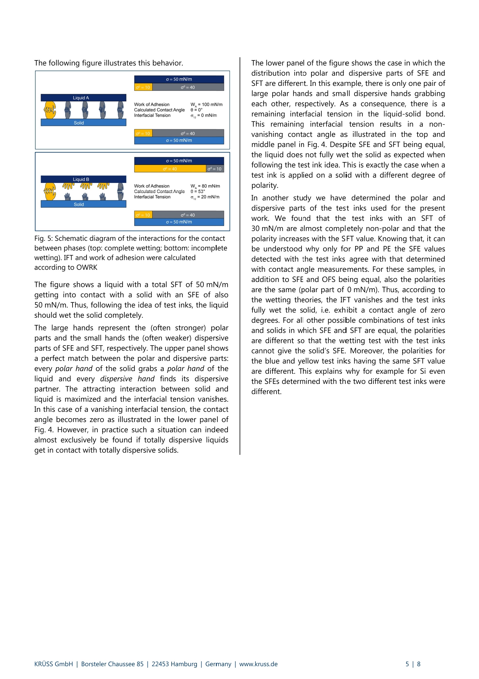

还剩6页未读,是否继续阅读?

产品配置单

克吕士科学仪器(上海)有限公司为您提供《油墨中表面能检测方案(接触角测量仪)》,该方案主要用于其他中表面能检测,参考标准--,《油墨中表面能检测方案(接触角测量仪)》用到的仪器有KRUSS MSA便携式接触角测量仪
推荐专场


相关方案
更多
该厂商其他方案
更多