


方案详情
文
利用德国LaVision公司的显微粒子成像测速分析软件包DaVis对串联气泡诱导喷射流动导致的细胞膜形变和生物效应进行了实验研究和分析。
方案详情

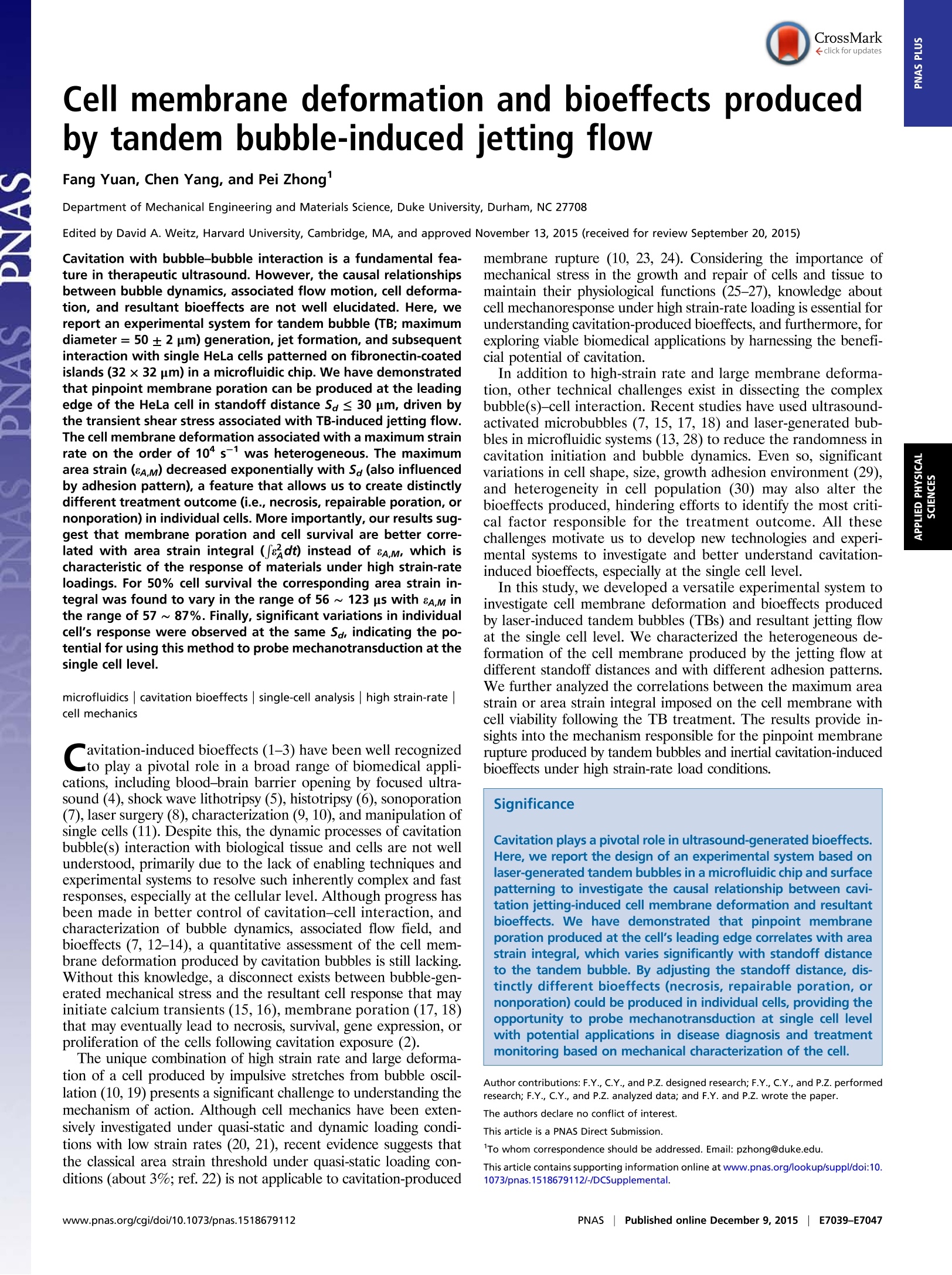
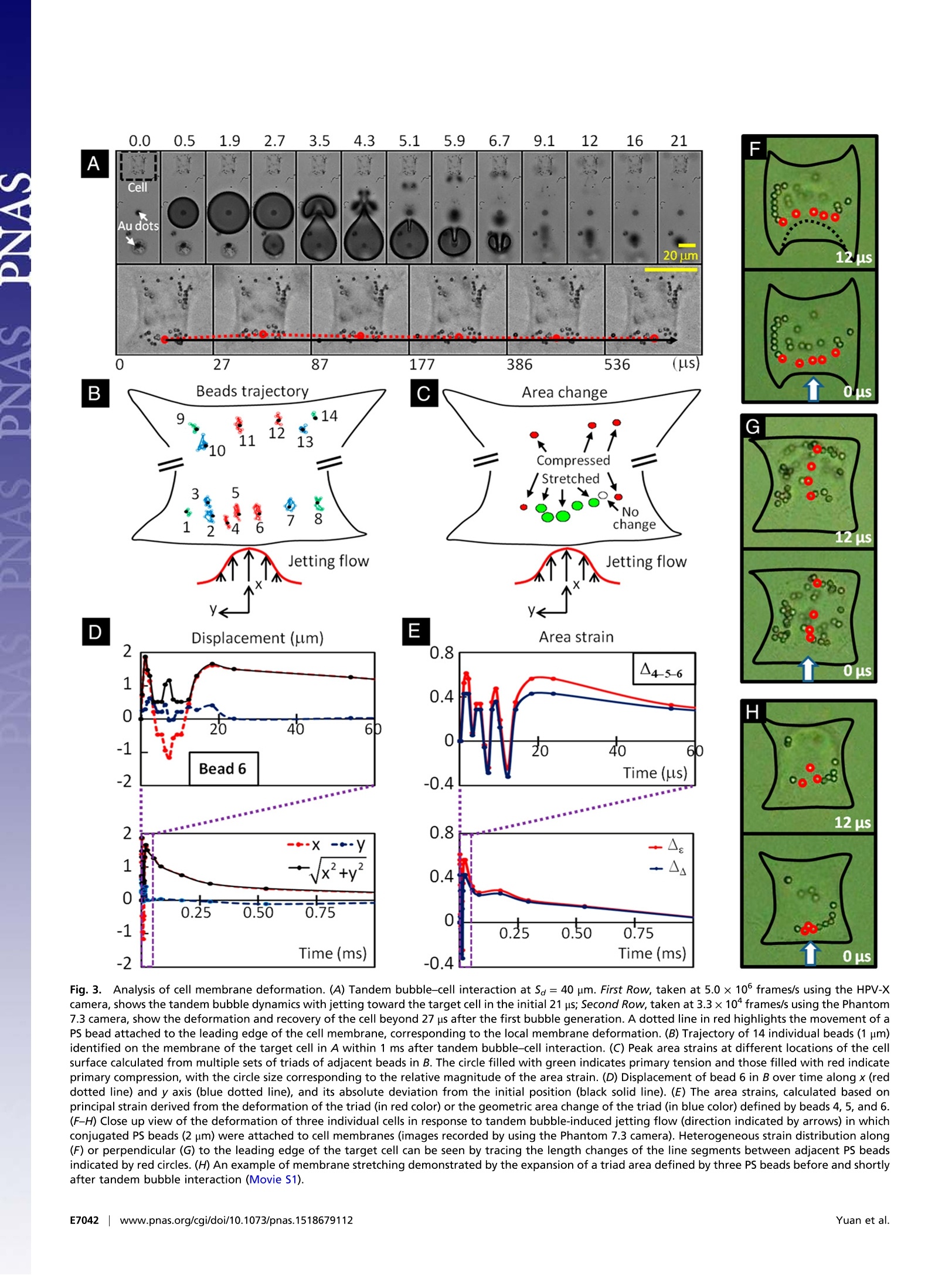
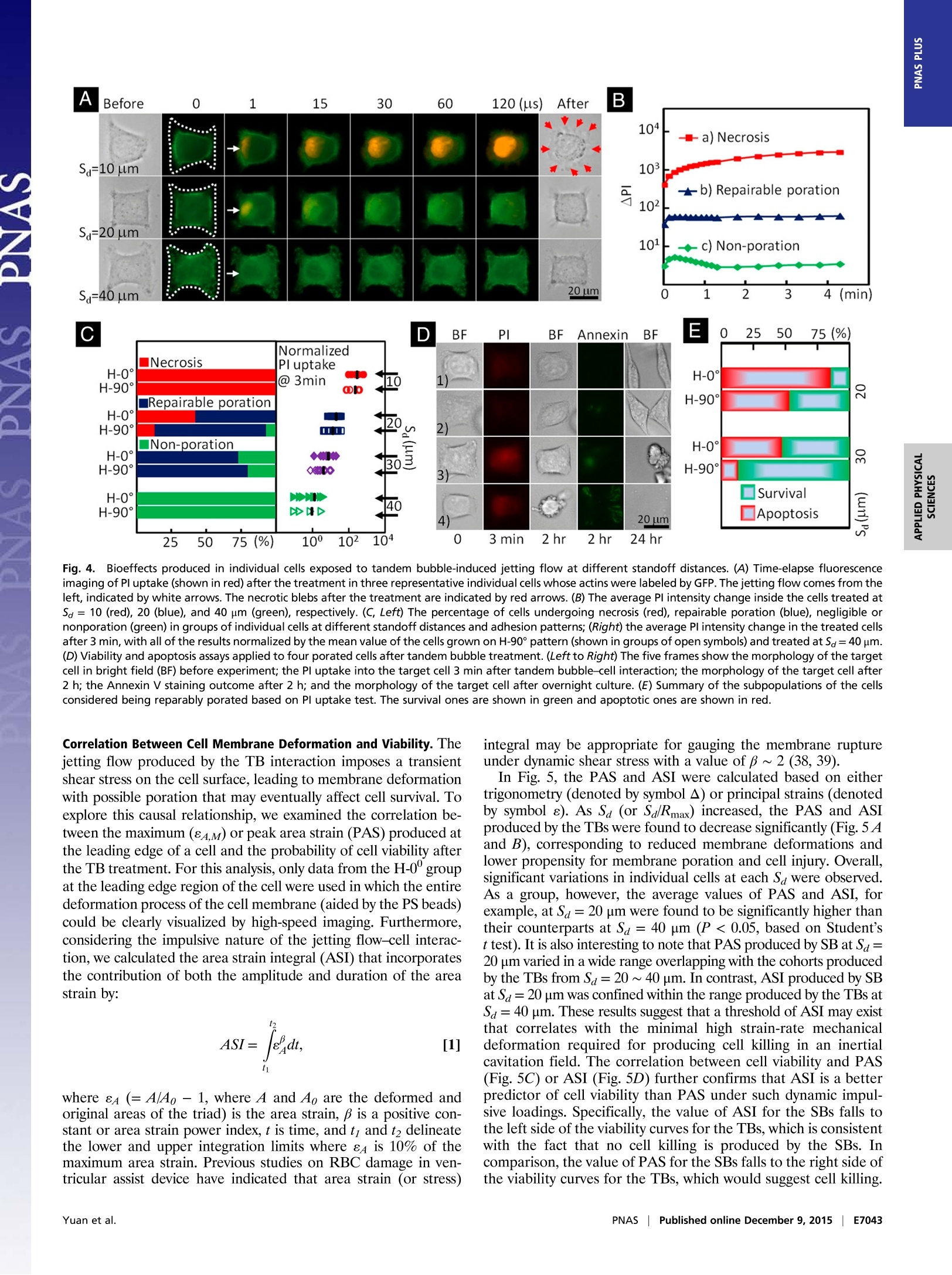
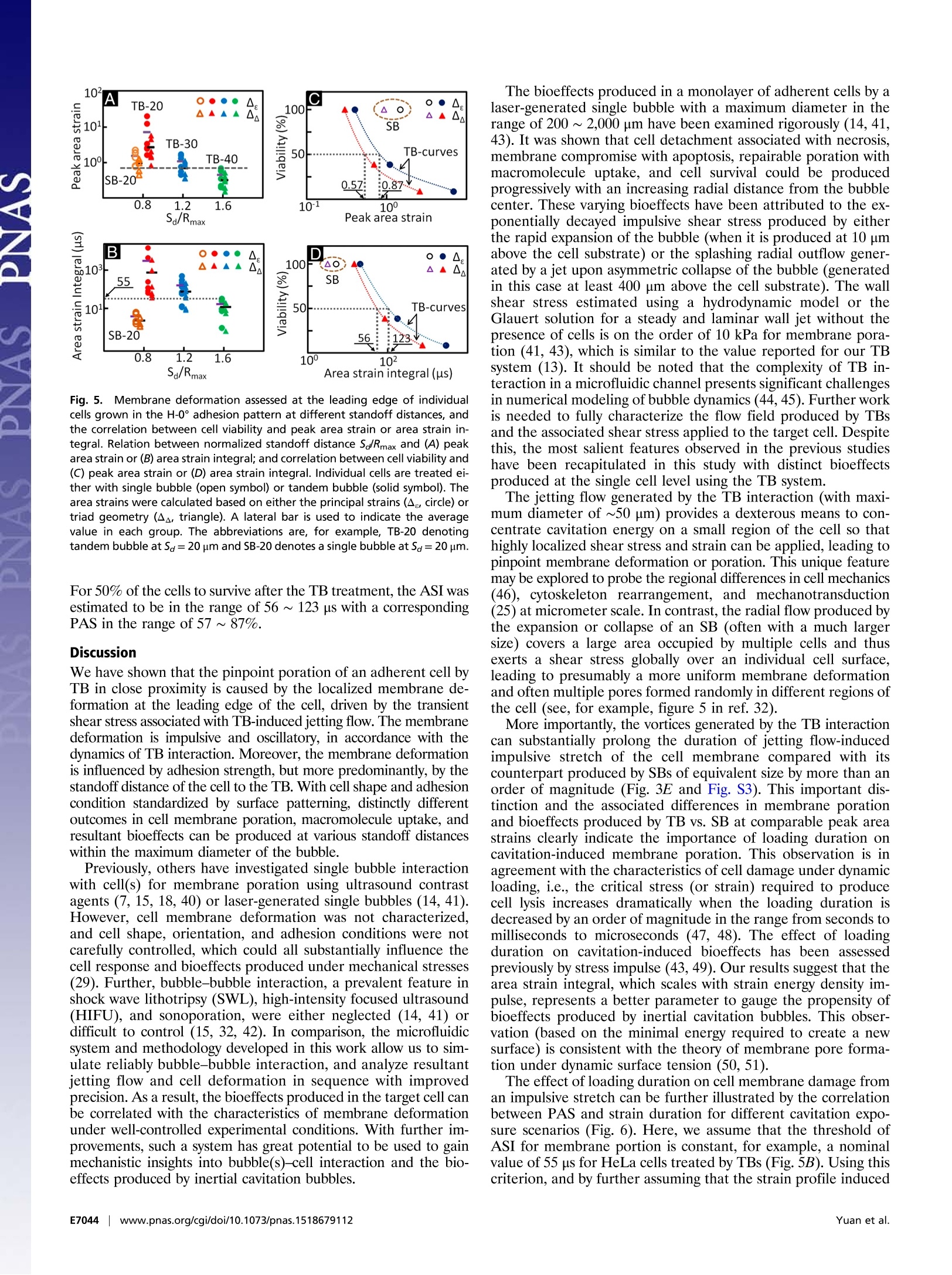
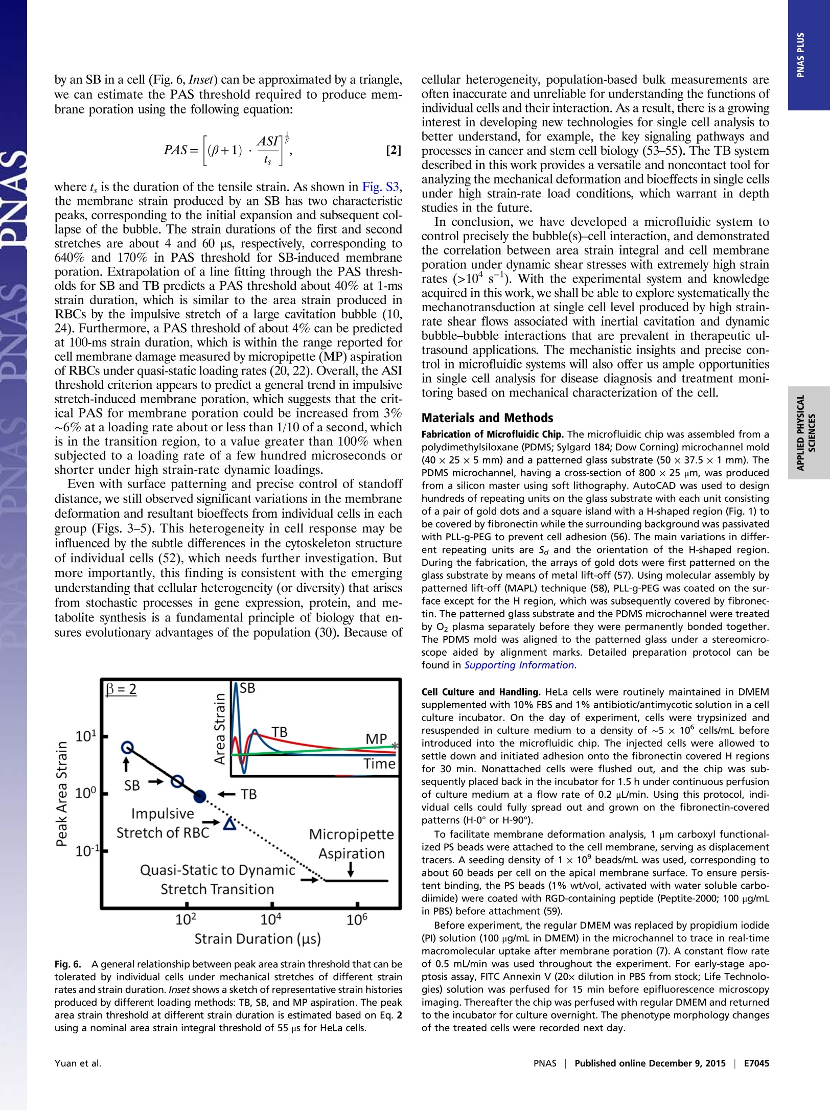
CrossMark10s-1). With the experimental system and knowledgeacquired in this work, we shall be able to explore systematically themechanotransduction at single cell level produced by high strain-rate shear flows associated with inertial cavitation and dynamicbubble-bubble interactions that are prevalent in therapeutic ul-trasound applications. The mechanistic insights and precise 0-con-trol in microfluidic systems will also offer us ample opportunitiesin single cell analysis for disease diagnosis and treatment moni-toring based on mechanical characterization of the cell. Materials and Methods Fabrication of Microfluidic Chip. The microfluidic chip was assembled from apolydimethylsiloxane (PDMS; Sylgard 184; Dow Corning) microchannel mold(40×25×5 mm) and a patterned glass substrate (50×37.5×1 mm). ThePDMS microchannel, having a cross-section of 800 × 25 um, was producedfrom a silicon master using soft lithography. AutoCAD was used to designhundreds of repeating units on the glass substrate with each unit consistingof a pair of gold dots and a square island with a H-shaped region (Fig.1) tobe covered by fibronectin while the surrounding background was passivatedwith PLL-g-PEG to prevent cell adhesion (56). The main variations in differ-ent repeating units are S。 and the orientation of the H-shaped region.During the fabrication, the arrays of gold dots were first patterned on theglass substrate by means of metal lift-off (57). Using molecular assembly bypatterned lift-off (MAPL) technique (58), PLL-g-PEG was coated on the sur-face except for the H region, which was subsequently covered by fibronec-tin. The patterned glass substrate and the PDMS microchannel were treatedby O2 plasma separately before they were permanently bonded together.The PDMS mold was aligned to the patterned glass under a stereomicro-scope aided by alignment marks. Detailed preparation protocol can befound in Supporting Information. Cell Culture and Handling. HeLa cells were routinely maintained in DMEMsupplemented with 10%FBS and 1% antibiotic/antimycotic solution in a cellculture incubator. On the day of experiment, cells were trypsinized andresuspended in culture medium to a density of ~5 × 10 cells/mL beforeintroduced into the microfluidic chip. The injected cells were allowed tosettle down and initiated adhesion onto the fibronectin covered H regionsfor 30 min. Nonattached cells were flushed out, and the chip was sub-sequently placed back in the incubator for 1.5 h under continuous perfusionof culture medium at a flow rate of 0.2 pL/min. Using this protocol, indi-vidual cells could fully spread out and grown on the fibronectin-coveredpatterns (H-0°or H-90). To facilitate membrane deformation analysis, 1 um carboxyl functional-ized PS beads were attached to the cell membrane, serving as displacementtracers. A seeding density of 1× 10°beads/mL was used, corresponding toabout 60 beads per cell on the apical membrane surface. To ensure persis-tent binding, the PS beads (1% wt/vol, activated with water soluble carbo-diimide) were coated with RGD-containing peptide (Peptite-2000; 100 ug/mLin PBS) before attachment (59). Before experiment, the regular DMEM was replaced by propidium iodide(PI) solution (100 ug/mL in DMEM) in the microchannel to trace in real-timemacromolecular uptake after membrane poration (7). A constant flow rateof 0.5 mL/min was used throughout the experiment. For early-stage apo-ptosis assay, FITC Annexin V (20x dilution in PBS from stock; Life Technolo-gies) solution was perfused for 15 min before epifluorescence microscopyimaging. Thereafter the chip was perfused with regular DMEM and returnedto the incubator for culture overnight. The phenotype morphology changesof the treated cells were recorded next day. TB Treatment and Image Acquisition. The microfluidic chip with cells wasplaced on the stage of a motorized inverted microscope (Axio Observer Z1;Zeiss). Two Q-switched Nd:YAG lasers (New Wave Research) were focusedthrough a 63x objective (LD Plan Neofluar; Zeiss) and projected on a pair ofgold dots to generate tandem bubble next to a target cell. Before treatmentthe original intracellular PI intensity and morphology of the cell wererecorded by a CCD camera (AxioCam MRc; Zeiss) using fluorescence andbright field (BF) imaging, respectively. Zeiss AxioVision software was usedto control illumination shutter, dichroic mirror, and switching betweentwo adjacent alternative positions in the rotating turret (within 200 ms).Transistor-transistor logic (TTL) trigger signals from a delay generator(565-8c; Berkeley Nucleonics Corporation) were used to synchronize lasersand cameras for TB generation and image acquisition. Bubble oscillation, jet formation, and resultant cell deformation were cap-tured by a high-speed video camera (HPV-X; Shimadzu) operated at 200-nsinterframe time (IFT) or 5 M fps with 100-ns exposure time for 25 us followingthe trigger of the first laser. Immediately after the TB-cell interaction, therecovery of the target cell membrane deformation was recorded for 1 msusing a second high-speed video camera (Phantom V7.3; Vision Research)operated at 20-us IFT with 1-us exposure time. Thereafter, the AxioCam cam-era, operated at 2-10 s IFT, was used to record PI diffusion from the porationsite into the target cell for 300 s; or in other experiments, Annexin Vand Plstaining performed at 2 and 24 h after the TB treatment. Characterization of TB-Generated Flow Field. PS beads (1 um, 2.6% wt/vol inculture medium) were used as tracers to map the flow field produced by TBs.High-speed image sequences of TB interaction recorded by the Shimadzucamera were analyzed offline using a commercial PIV software (DaVis 7.2;LaVision). The image field (100 ×200 um) was divided into multiple interro-gation windows of 16 × 16 um each with 75% overlap, and multipass itera-tions and regional filters were applied to reduce the error in velocity fieldcomputation (see details in Supporting Information). To improve the accuracy 1. Rooney JA (1970) Hemolysis near an ultrasonically pulsating gas bubble. Science169(3948):869-871. 2. Miller MW, Miller DL, Brayman AA (1996) A review of in vitro bioeffects of inertial ul-trasonic cavitation from a mechanistic perspective. Ultrasound Med Bio/ 22(9):1131-1154. 3. Mitragotri S (2005) Healing sound: The use of ultrasound in drug delivery and othertherapeutic applications. Nat Rev Drug Discov 4(3):255-260. 4. Hynynen K, McDannold N, Sheikov NA, Jolesz FA, Vykhodtseva N (2005) Local andreversible blood-brain barrier disruption by noninvasive focused ultrasound at fre-quencies suitable for trans-skull sonications. Neuroimage 24(1):12-20. 5. Zhong P (2013) Shock Wave Lithotripsy. Bubble Dynamics and Shock Waves, ShockWave Science and Technology Reference Library, ed Delale CF (Springer, Berlin), Vol 8,pp 291-338. 6. Xu Z, Hall TL, Fowlkes JB, Cain CA (2007) Effects of acoustic parameters on bubblecloud dynamics in ultrasound tissue erosion (histotripsy). J Acoust Soc Am 122(1):229-236. 7. Fan Z, Liu H, Mayer M, Deng CX (2012) Spatiotemporally controlled single cellsonoporation. Proc Nat/ Acad Sci USA 109(41):16486-16491. 8. Vogel A, Noack J, Huttman G, Paltauf G (2005) Mechanisms of femtosecond lasernanosurgery of cells and tissues. App/ Phys B 81(8):1015-1047. 9. Quinto-Su PA, Huang XH, Gonzalez-Avila SR, Wu T, Ohl CD (2010) Manipulation andmicrorheology of carbon nanotubes with laser-induced cavitation bubbles. Phys RevLett 104(1):014501. 10. Li F, Chan CU, Ohl CD (2013) Yield strength of human erythrocyte membranes toimpulsive stretching. Biophys J 105(4):872-879. 11. Lautz J, Sankin G, Yuan F,Zhong P (2010) Displacement of particles in microfluidics bylaser-generated tandem bubbles. App/ Phys Lett 97(18):183701. 12. Marmottant P, Hilgenfeldt S (2003) Controlled vesicle deformation and lysis by singleoscillating bubbles. Nature 423(6936):153-156. 13. Sankin GN, Yuan F, Zhong P (2010) Pulsating tandem microbubble for localized anddirectional single-cell membrane poration. Phys Rev Lett 105(7):078101. 14. Rau KR, Quinto-Su PA, Hellman AN, Venugopalan V (2006) Pulsed laser microbeam-induced cell lysis: Time-resolved imaging and analysis of hydrodynamic effects.Biophys J91(1):317-329. 15. Kudo N, Okada K, Yamamoto K (2009) Sonoporation by single-shot pulsed ultrasoundwith microbubbles adjacent to cells. Biophys J 96(12):4866-4876. 16. Fan Z, Kumon RE, Park J, Deng CX (2010) Intracellular delivery and calcium transients generated in sonoporation facilitated by microbubbles.J Control Release 142(1):31-39.17. Prentice P, Cuschierp A, Dholakia K, Prausnitz M, Campbell P(2005) Membrane dis- ruption by optically controlled microbubble cavitation. Nat Phys 1(2):107-110.18. van Wamel A, et al. (2006) Vibrating microbubbles poking individual cells: Drug transfer into cells via sonoporation. J Control Release 112(2):149-155. 19. Quinto-Su PA, Kuss C, Preiser PR, Ohl CD (2011) Red blood cell rheology using singlecontrolled laser-induced cavitation bubbles. Lab Chip 11(4):672-678. 20. Hategan A, Law R, Kahn S, Discher DE (2003) Adhesively-tensed cell membranes: Lysiskinetics and atomic force microscopy probing. Biophys J 85(4):2746-2759. of velocity field calculation, each flow field was recorded up to 3 times underthe same experimental condition and the resultant images were superimposedbefore PIV analysis. To further illustrate the characteristics of the flow motion produced by theTBs, the deformation of five parallel imaginary material lines, each 40 um inlength and initially placed at Sa=20, 30, 40, 50, 60 um, respectively, weretraced. Each material line consisted of 1,000 individual material points theincremental displacements of which at consecutive time points were calcu-lated based on the local velocity interpolated from the PlV results. Byinterconnecting these material points at different time steps, the evolutionof the material lines in TB-induced flow field could be visualized (Fig. 2C). Calculation of Cell Membrane Deformation. A triangulation scheme wasadapted to analyze the local membrane strain (60). The triangular areas se-lected for strain calculation were in the peripheral region of the cell awayfrom the nucleus, and therefore the beads' displacement was confined withinthe focal plane of the objective lens. The beads were traced over time andtheir coordinates were recorded from the high-speed images. Area straincalculations were carried out based on principal strains (see details in Sup-porting Information) determined by using a custom code written in Matlab(The MathWorks) following established protocols (61, 62). For comparison,thearea strain was also calculated based on trigonometry to determine thechange of the triangular area encompassed by the triad of beads. ACKNOWLEDGMENTS. The authors acknowledge Georgy Sankin and YingZhang for their technical support, and Harold Erickson and Tomoo Ohashi forproviding the LifeAct-GFP DNA plasmid. The authors thank Todd Rumbaugh ofHadland Imaging for providing the Shimadzu HPV-X camera. The authors alsowant to express their gratitude to Farshid Guilak, Brenton Hoffman, andFenfang Li for reading through the manuscript and providing valuablecomments. This work was supported in part by NIH through Grants R03-EB017886-01A1 and R37-DK052985-18. 21. Wirtz D, Konstantopoulos K, Searson PC (2011) The physics of cancer: The role ofphysical interactions and mechanical forces in metastasis. Nat Rev Cancer 11(7):512-522. 22. Evans EA, Waugh R, Melnik L (1976) Elastic area compressibility modulus of red cellmembrane. Biophys J 16(6):585-595. 23. Waugh RE (2014) Forty-percent area strain in red cell membranes? Doubtful. BiophysJ106(8):1834-1835. 24. Li F, Chan CU, Ohl CD (2014) Rebuttal to a comment by Richard E. Waugh on ourarticle "Yield strength of human erythrocyte membranes to impulsive stretching".Biophys J 106(8):1832-1833. 25. Bao G, Suresh S (2003) Cell and molecular mechanics of biological materials. NatMater 2(11):715-725. 26. Discher D, et al. (2009) Biomechanics: Cell research and applications for the nextdecade. Ann Biomed Eng 37(5):847-859. 27. Guilak F, et al.(2009) Control of stem cell fate by physical interactions with the ex-tracellular matrix. Cell Stem Cell 5(1):17-26. 28. Zwaan E, Le Gac S, Tsuji K, Ohl C-D (2007) Controlled cavitation in microfluidic sys-tems. Phys Rev Lett 98(25):254501. 29. Chen CS, Mrksich M, Huang S, Whitesides GM, Ingber DE (1997) Geometric control ofcell life and death. Science 276(5317):1425-1428. 30. Wang D, Bodovitz S (2010) Single cell analysis: The new frontier in 'omics’. TrendsBiotechno/ 28(6):281-290. 31. Yuan F, Sankin G, Zhong P (2011) Dynamics of tandem bubble interaction in a mi-crofluidic channel. J Acoust Soc Am 130(5):3339-3346. 32. Ohl C-D, et al. (2006) Sonoporation from jetting cavitation bubbles. Biophys J 91(11):4285-4295. 33. Hoffman BD, Grashoff C, Schwartz MA (2011) Dynamic molecular processes mediatecellular mechanotransduction. Nature 475(7356):316-323. 34. Janmey PA, McCulloch CA (2007) Cell mechanics: Integrating cell responses to me-chanical stimuli. Annu Rev Biomed Eng 9:1-34. 35. Fan Z, et al. (2013) Acoustic tweezing cytometry for live-cell subcellular modulation ofintracellular cytoskeleton contractility. Sci Rep 3:2176. 36. Li ZG, Liu AQ, Klaseboer E, Zhang JB, Ohl CD(2013) Single cell membrane poration by bubble-induced microjets in a microfluidic chip. Lab Chip 13(6):1144-1150.37. Barros LF, et al. (2003) Apoptotic and necrotic blebs in epithelial cells display similar neck diameters but different kinase dependency. Cell Death Differ 10(6):687-697. 38. Arora D, Behr M, Pasquali M (2004) A tensor-based measure for estimating blooddamage. Artif Organs 28(11):1002-1015. 39. Grigioni M, et al. (2004) The power-law mathematical model for blood damageprediction: Analytical developments and physical inconsistencies. Artif Organs 28(5):467-475. 40. Hu Y, Wan JMF, Yu ACH (2013) Membrane perforation and recovery dynamics inmicrobubble-mediated sonoporation.Ultrasound Med Bio/ 39(12):2393-2405. 41. Dijkink R, et al. (2008) Controlled cavitation-cell interaction: Trans-membrane trans-port and viability studies. Phys Med Biol 53(2):375-390. 42.Kooiman K, Foppen-Harteveld M, van der Steen AFW, de Jong N (2011) Sonoporation ofendothelial cells by vibrating targeted microbubbles. J Control Release 154(1):35-41. 43. Compton JL, Hellman AN,Venugopalan V (2013) Hydrodynamic determinants of cellnecrosis and molecular delivery produced by pulsed laser microbeam irradiation ofadherent cells. Biophys J105(9):2221-2231. 44. Hsiao CT, et al. (2013) Modelling single- and tandem-bubble dynamics between twoparallel plates for biomedical applications. J Fluid Mech 716:137-170. 45. Q(uinto-Su PA, Ohl C-D (2009) Interaction between two laser-induced cavitationbubbles in a quasi-two-dimensional geometry. J Fluid Mech 633:425-435. 46. Wu P-H, et al. (2012) High-throughput ballistic injection nanorheology to measure cellmechanics. Nat Protoc 7(1):155-170. 47. Lokhandwalla M, Sturtevant B (2001) Mechanical haemolysis in shock wave lithotripsy(SWL): I. Analysis of cell deformation due to SWL flow-fields. Phys Med Biol 46(2):413-437. 48.Leverett LB, Hellums JD, Alfrey CP, Lynch EC (1972) Red blood cell damage by shearstress. Biophys J 12(3):257-273. 49. Forbes MM, O'Brien WD, Jr (2012) Development of a theoretical model describingsonoporation activity of cells exposed to ultrasound in the presence of contrastagents.J Acoust Soc Am 131(4):2723-2729. 50. Bicout DJ, Kats E (2012) Rupture of a biomembrane under dynamic surface tension.Phys Rev E Stat Nonlin Soft Matter Phys 85(3 Pt 1):031905. 51. Evans E, Ludwig F (2000) Dynamic strengths of molecular anchoring and materialcohesion in fluid biomembranes. J Phys Condens Matter 12(8A):A315-A320. 52. Fletcher DA, Mullins RD (2010) Cell mechanics and the cytoskeleton. Nature 463(7280):485-492. 53. Weaver WM,et al. (2014) Advances in high-throughput single-cell microtechnologies.Curr Opin Biotechno/ 25:114-123. 54. Gossett DR, et al.(2012) Hydrodynamic stretching of single cells for large populationmechanical phenotyping. Proc Natl Acad Sci USA 109(20):7630-7635. 55. Spiller DG, Wood CD, Rand DA, White MRH (2010) Measurement of single-cell dynamics.Nature 465(7299):736-745. 56. Michel R, et al. (2002) Selective molecular assembly patterning: A new approach tomicro-and nanochemical patterning of surfaces for biological applications. Langmuir18(8):3281-3287. 57. Baldwin RP,et al.(2002) Fully integrated on-chip electrochemical detection for cap-illary electrophoresis in a microfabricated device. Anal Chem 74(15):3690-3697. 58. Falconnet D, Koenig A, Assi T, Textor M (2004) A combined photolithographic andmolecular-assembly approach to produce functional micropatterns for applications inthe biosciences. Adv Funct Mater 14(8):749-756. 59. Wang N, Butler JP, Ingber DE (1993) Mechanotransduction across the cell surface andthrough the cytoskeleton. Science 260(5111):1124-1127. 60. Fung YC (1965) Foundations of Solid Mechanics (Prentice Hall, Upper Saddle River, NJ).nci61. Barbee KA, Macarak EJ, Thibault LE (1994) Strain measurements in cultured vascular smooth muscle cells subjected to mechanical deformation. Ann Biomed Eng 22(1):14-22. 62. Simon Sl, Schmid-Schonbein GW (1990) Cytoplasmic strains and strain rates in motilepolymorphonuclear leukocytes. Biophys J 58(2):319-332. 63. Huang NP, et al. (2001) Poly(L-lysine)-g-poly(ethylene glycol) layers on metal oxidesurfaces: Surface-analytical characterization and resistance to serum and fibrinogenadsorption. Langmuir 17(2):489-498. 64. Adrian RJ (1991) Particle-imaging techniques for experimental fluid-mechanics. AnnuRev Fluid Mech 23:261-304. 65. Raffel M, Willert CE, Wereley ST, Kompenhans J (1998) Image Evaluation Methods for PIV. Particle Image Velocimetry: A Practical Guide (Springer, Berlin), pp 123-176.66. Raffel M, Willert CE, Wereley ST, Kompenhans J (1998) Post-Processing of PIV Data. Particle Image Velocimetry: A Practical Guide (Springer, Berlin), pp 177-208. 67. Riedl J, et al. (2008) Lifeact: A versatile marker to visualize F-actin. Nat Methods 5(7):605-607. www.pnas.org/cgi/doi/pnas.NAS | Published online December , EE Yuan et al.Eww.pnas.org/cgi/doi/pnas. Cavitation with bubble–bubble interaction is a fundamental featurein therapeutic ultrasound. However, the causal relationshipsbetween bubble dynamics, associated flow motion, cell deformation,and resultant bioeffects are not well elucidated. Here, wereport an experimental system for tandem bubble (TB; maximumdiameter = 50 ± 2 μm) generation, jet formation, and subsequentinteraction with single HeLa cells patterned on fibronectin-coatedislands (32 × 32 μm) in a microfluidic chip. We have demonstratedthat pinpoint membrane poration can be produced at the leadingedge of the HeLa cell in standoff distance Sd ≤ 30 μm, driven bythe transient shear stress associated with TB-induced jetting flow.The cell membrane deformation associated with a maximum strainrate on the order of 104 s−1 was heterogeneous. The maximumarea strain (eA,M) decreased exponentially with Sd (also influencedby adhesion pattern), a feature that allows us to create distinctlydifferent treatment outcome (i.e., necrosis, repairable poration, ornonporation) in individual cells. More importantly, our results suggestthat membrane poration and cell survival are better correlatedwith area strain integral (Re2Adt) instead of eA,M, which ischaracteristic of the response of materials under high strain-rateloadings. For 50% cell survival the corresponding area strain integralwas found to vary in the range of 56 ∼ 123 μs with eA,M inthe range of 57 ∼ 87%. Finally, significant variations in individualcell’s response were observed at the same Sd, indicating the potentialfor using this method to probe mechanotransduction at thesingle cell level.
确定
还剩7页未读,是否继续阅读?

产品配置单
北京欧兰科技发展有限公司为您提供《细胞中细胞膜形变检测方案(粒子图像测速)》,该方案主要用于其他中细胞膜形变检测,参考标准--,《细胞中细胞膜形变检测方案(粒子图像测速)》用到的仪器有显微粒子成像测速系统(Micro PIV)
推荐专场


相关方案
更多
该厂商其他方案
更多