


方案详情
文
Two-dimensional velocity fields around a freely swimming freshwater black shark fish in longitudinal (XZ) plane and
transverse (YZ) plane are measured using digital particle image velocimetry (DPIV). By transferring momentum to
the fluid, fishes generate thrust. Thrust is generated not only by its caudal fin, but also using pectoral and anal fins,
the contribution of which depends on the fish’s morphology and swimming movements. These fins also act as roll
and pitch stabilizers for the swimming fish. In this paper, studies are performed on the flow induced by fins of freely
swimming undulatory carangiform swimming fish (freshwater black shark, L = 26 cm) by an experimental hydrodynamic
approach based on quantitative flow visualization technique. We used 2D PIV to visualize water flow pattern
in the wake of the caudal, pectoral and anal fins of swimming fish at a speed of 0.5–1.5 times of body length per
second. The kinematic analysis and pressure distribution of carangiform fish are presented here. The fish body and fin
undulations create circular flow patterns (vortices) that travel along with the body waves and change the flow around
its tail to increase the swimming efficiency. The wake of different fins of the swimming fish consists of two counterrotating
vortices about the mean path of fish motion. These wakes resemble like reverse von Karman vortex street
which is nothing but a thrust-producing wake. The velocity vectors around a C-start (a straight swimming fish bends
into C-shape) maneuvering fish are also discussed in this paper. Studying flows around flapping fins will contribute to
design of bioinspired propulsors for marine vehicles.
方案详情

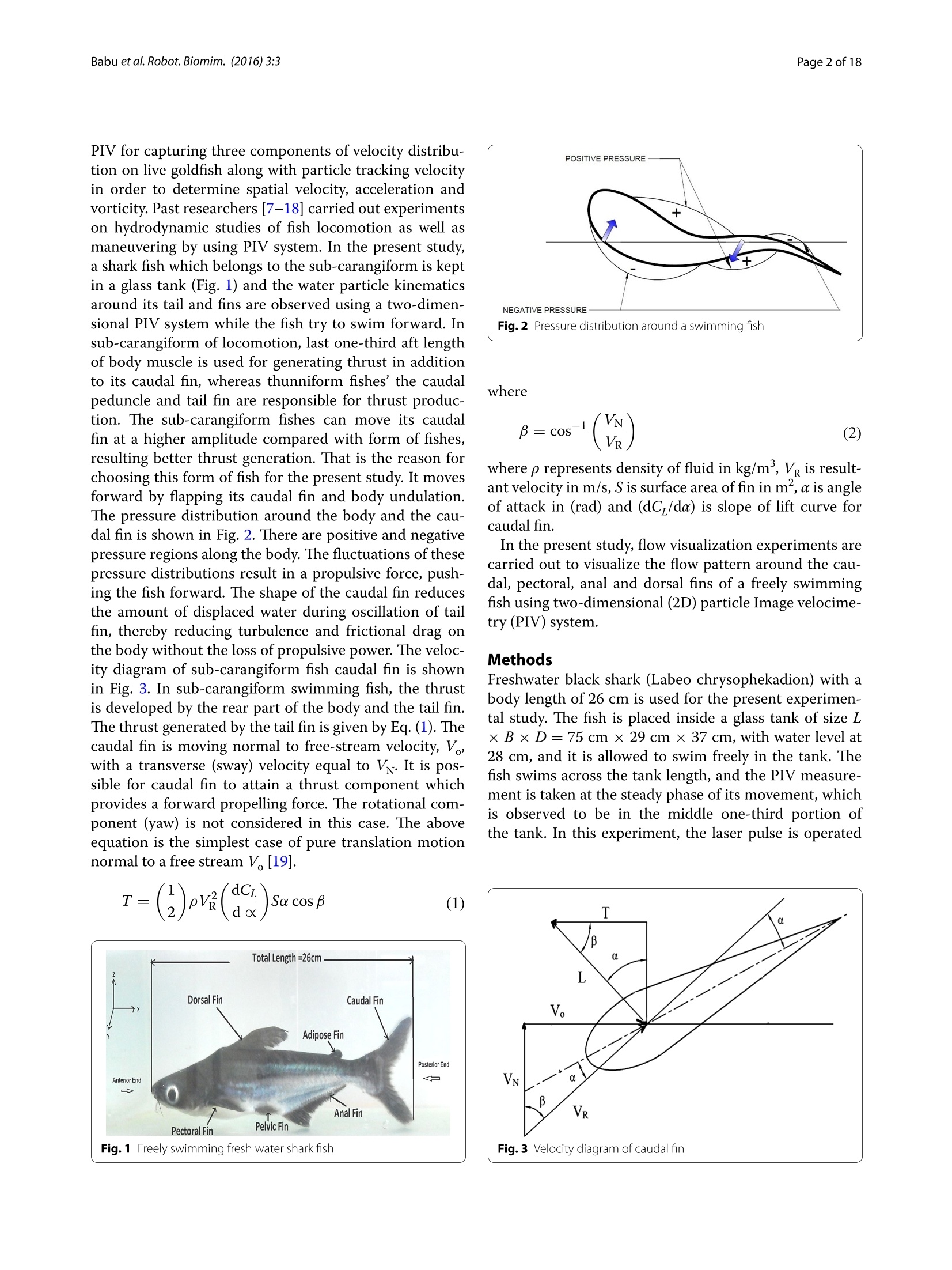
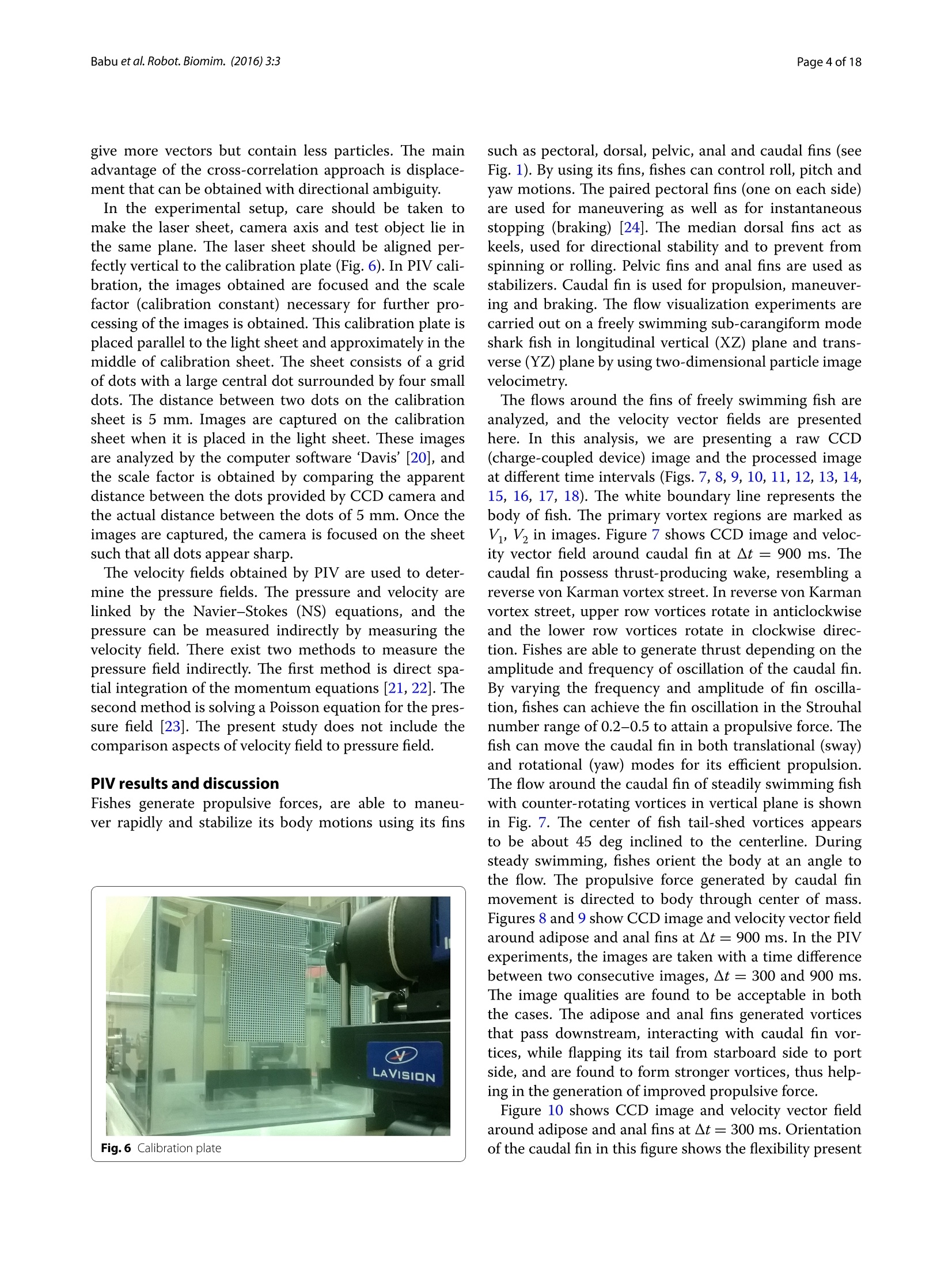
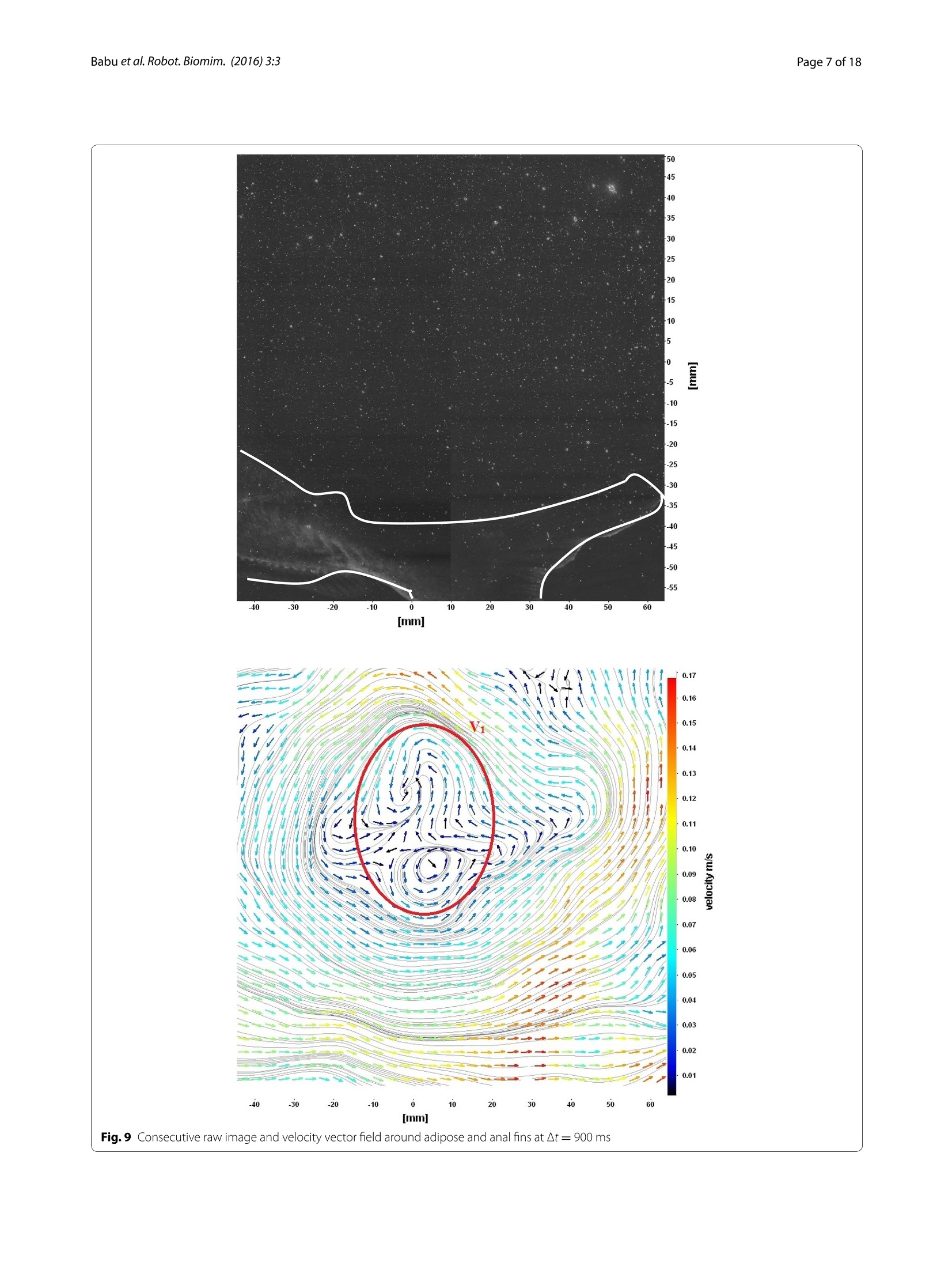
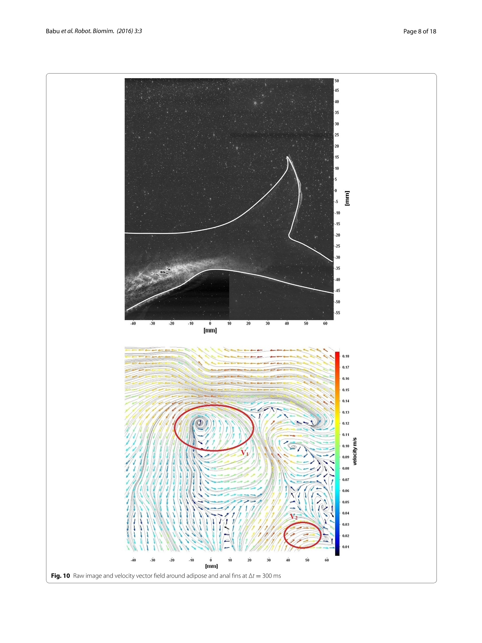
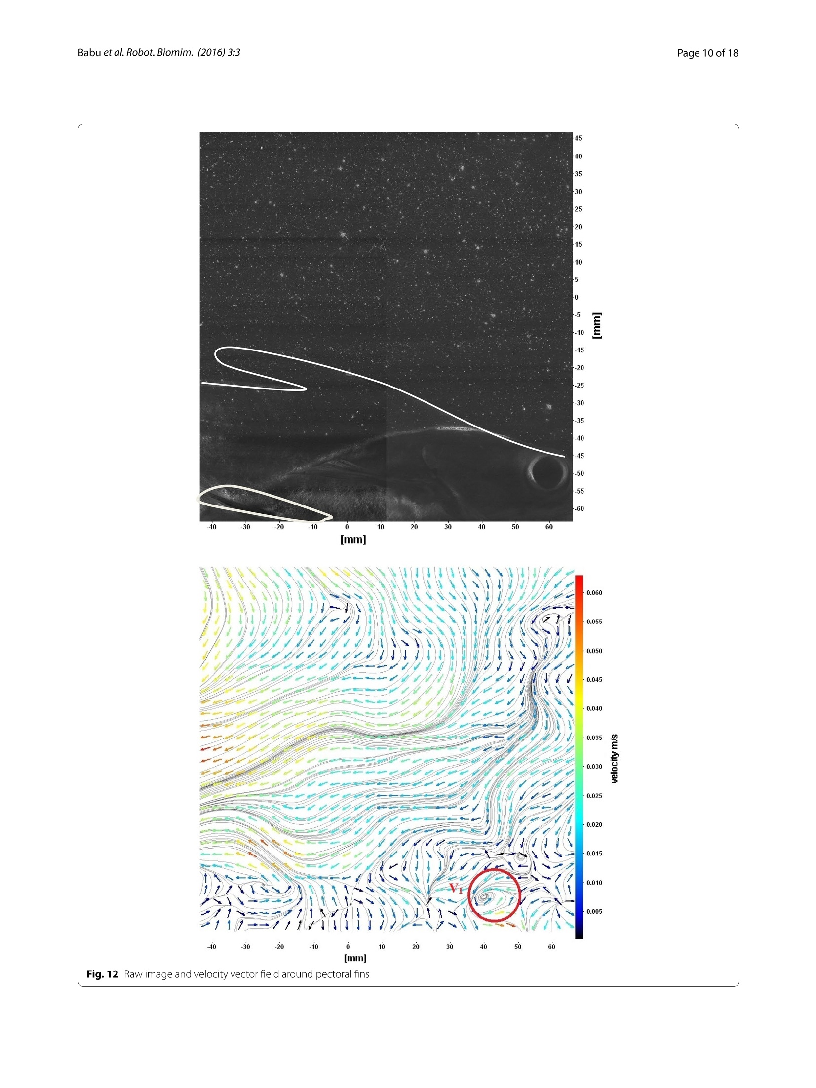
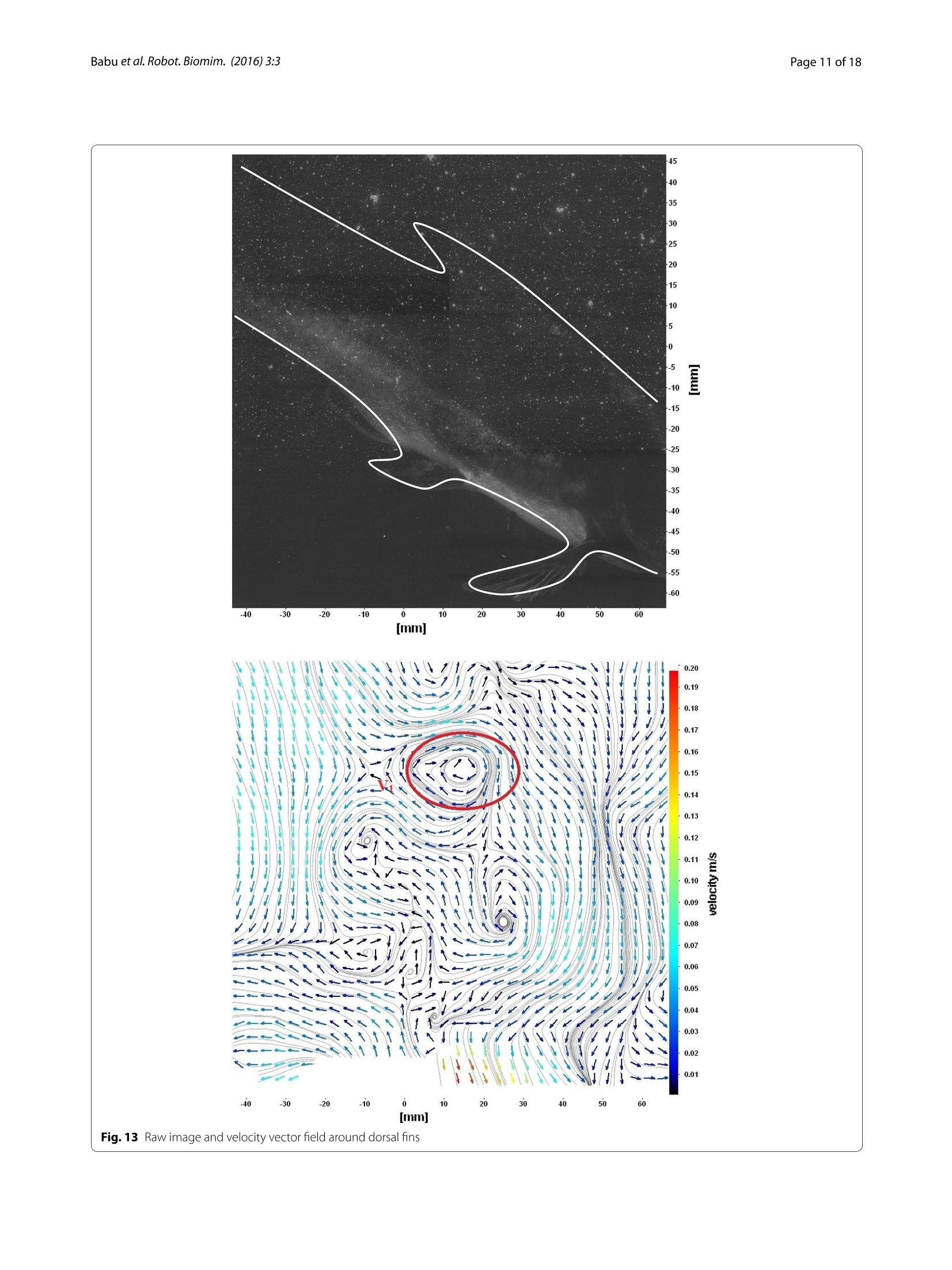
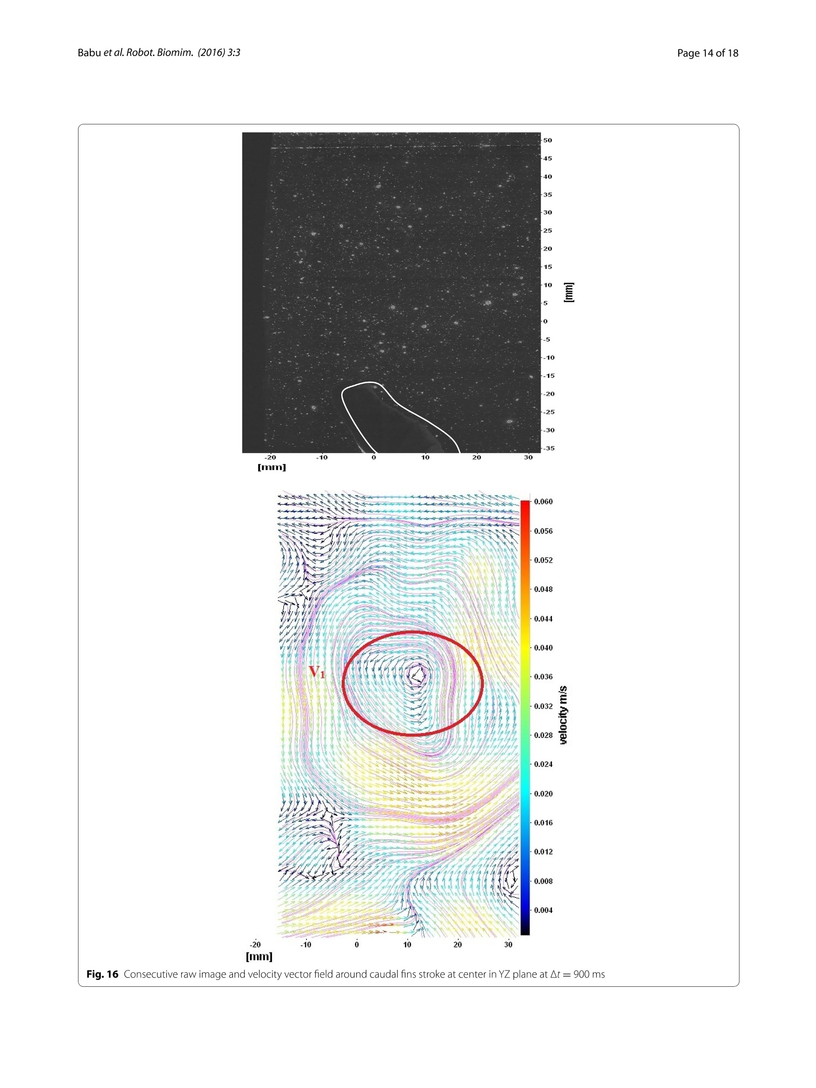
Robotics and BiomimeticsBabu et al.Robot. Biomim. (2016)3:3DOI 10.1186/s40638-016-0036-0 Babu et al. Robot. Biomim. (2016) 3:3. Page 2 of 18 RESEARCH O)pen Access CrossMarkHydrodynamic study of freely swimmingshark fish propulsion for marine vehicles using2D particle image velocimetry Mannam Naga Praveen Babu'*, J. M. Mallikarjunaand P.Krishnankuttyl Abstract Two-dimensional velocity fields around a freely swimming freshwater black shark fish in longitudinal (XZ) plane andtransverse (YZ) plane are measured using digital particle image velocimetry (DPIV). By transferring momentum tothe fluid, fishes generate thrust. Thrust is generated not only by its caudal fin, but also using pectoral and anal fins,the contribution of which depends on the fish's morphology and swimming movements. These fins also act as rolland pitch stabilizers for the swimming fish. In this paper, studies are performed on the flow induced by fins of freelyswimming undulatory carangiform swimming fish (freshwater black shark, L=26 cm) by an experimental hydrody-namic approach based on quantitative flow visualization technique. We used 2D PIV to visualize water flow patternin the wake of the caudal, pectoral and anal fins of swimming fish at a speed of 0.5-1.5 times of body length persecond. The kinematic analysis and pressure distribution of carangiform fish are presented here. The fish body and finundulations create circular flow patterns (vortices) that travel along with the body waves and change the flow aroundits tail to increase the swimming efficiency. The wake of different fins of the swimming fish consists of two counter-rotating vortices about the mean path of fish motion. These wakes resemble like reverse von Karman vortex streetwhich is nothing but a thrust-producing wake. The velocity vectors around a C-start (a straight swimming fish bendsinto C-shape) maneuvering fish are also discussed in this paper. Studying flows around flapping fins will contribute todesign of bioinspired propulsors for marine vehicles. Keywords: Carangiform swimming, Caudal fin locomotion, Flow visualization, Propulsor hydrodynamics, Particleimage velocimetry, Pectoral fins, Reverse von Karman vortex street, Wake Background Aquatic animal propulsors are classified into lift-based(e.g., penguins, turtle forelimb propulsion and aerialbirds), undulation (e.g., fishes, eels), drag-based (e.g.,duck paddling) and jet mode (e.g., jelly fish, squids).Fishes use a combination of lift-based and undulatingmodes mainly using its undulating body, pectoral andcaudal fins to achieve propulsive forces. Fishes also gen-erate thrust by using its tail fin, paired fins and its body.Certain combinations of flapping motions and anglesof body achieve greater speed and better maneuvering ( *Correspondence: m praveenmn@gmail.com;oe13d006@smail.iit m .ac.in ' D epartment of Ocean Engineering, Indian Institu t e o f Technology Madras, Chennai 600 036,India ) ( F ull list of authori n formati o n i s a vailable a t the end of the article ) capabilities. Flapping foil propulsion systems, resemblingfish fin propulsion mode, are found to be much more effi-cient than the conventional screw propellers [1, 2]. Theapplication of fish propulsion to water crafts is found tohave higher propulsive efficiency, better maneuveringcapabilities, less vibrations, low emissions and more eco-friendly. Biological aquatic animal locomotion, its mech-anism and their successful application to marine vehiclesare being studied by different researchers. Muller[3] used2D PIV to visualize the flow around the aquatic animalsand to demonstrate the creation of vorticity and theircontribution to thrust generation. Muller et al. [4] studiedthe water velocity near fish body using PIV and describedthe wake mechanism behind it.Drucker and Lauder [5]studied the bluegill sunfish pectoral fins 3D wake struc-tures using PIV. Sakakibara et al. [6] used stereoscopic ( ◎ 2016 Babu et al . This art ic le is distrib u ted under t h e ter m s o f th e Creativ e C o mmon s Attribution 4 . 0 I n terna t ional Li c en s e ( http://cre at i v ec ommo n s. o r g / li ce n ses /b y /4. 0/ ), w h ich permits unre s tricted use, distribution, a n d reproduction in an y medium, p rovi d ed you give appropriate credit to the original author(s) and the source, provide a link to the Creative Common s license, a nd indicate if changes were made. ) PIV for capturing three components of velocity distribu-tion on live goldfish along with particle tracking velocityin order to determine spatial velocity, acceleration andvorticity. Past researchers [7-18] carried out experimentson hydrodynamic studies of fish locomotion as well asmaneuvering by using PIV system. In the present study,a shark fish which belongs to the sub-carangiform is keptin a glass tank (Fig. 1) and the water particle kinematicsaround its tail and fins are observed using a two-dimen-sional PIV system while the fish try to swim forward. Insub-carangiform of locomotion, last one-third aft lengthof body muscle is used for generating thrust in additionto its caudal fin, whereas thunniform fishes'the caudalpeduncle and tail fin are responsible for thrust produc-tion. The sub-carangiform fishes can move its caudalfin at a higher amplitude compared with form of fishes,resulting better thrust generation. That is the reason forchoosing this form of fish for the present study. It movesforward by flapping its caudal fin and body undulation.The pressure distribution around the body and the cau-dal fin is shown in Fig. 2. There are positive and negativepressure regions along the body. The fluctuations of thesepressure distributions result in a propulsive force, push-ing the fish forward. The shape of the caudal fin reducesthe amount of displaced water during oscillation of tailfin, thereby reducing turbulence and frictional drag onthe body without the loss of propulsive power. The veloc-ity diagram of sub-carangiform fish caudal fin is shownin Fig. 3. In sub-carangiform swimming fish, the thrustis developed by the rear part of the body and the tail fin.The thrust generated by the tail fin is given by Eq. (1). Thecaudal fin is moving normal to free-stream velocity, V,with a transverse (sway) velocity equal to V. It is pos-sible for caudal fin to attain a thrust component whichprovides a forward propelling force. The rotational com-ponent (yaw) is not considered in this case. The aboveequation is the simplest case of pure translation motionnormal to a free stream V[19]. Fig.2 Pressure distribution around a swimming fish where where p represents density of fluid in kg/m’, V is result-ant velocity in m/s, S is surface area of fin in m , a is angleof attack in (rad) and (dC,/da) is slope of lift curve forcaudal fin. In the present study,flow visualization experiments arecarried out to visualize the flow pattern around the cau-dal, pectoral, anal and dorsal fins of a freely swimmingfish using two-dimensional (2D) particle Image velocime-try (PIV) system. Methods Freshwater black shark (Labeo chrysophekadion) with abody length of 26 cm is used for the present experimen-tal study. The fish is placed inside a glass tank of size L× B×D=75 cm × 29 cm × 37 cm, with water level at28 cm, and it is allowed to swim freely in the tank. Thefish swims across the tank length, and the PIV measure-ment is taken at the steady phase of its movement, whichis observed to be in the middle one-third portion ofthe tank. In this experiment, the laser pulse is operated Fig.1 Freely swimming fresh water shark fish Fig.3 Velocity diagram of caudal fin continuously and fish will always cross this laser planein multiple times with same time interval. Then, a rangeof images is selected for processing velocity fields. Fromthe visual observations,based on the recorded video, theStrouhal number of the freely swimming shark fish usedin this experiment is approximately 0.23, where the tailfin oscillation frequency is 0.6 Hz, amplitude is 0.1 m andthe fish swimming speed is 0.26 m/s. Experimental setup Two-dimensional PIV technique is used to study the flowaround a swimming fish. This helps in clearly under-standing the instantaneous velocity vector fields of theflow field around the fish. It is a non-intrusive experi-mental technique which can measure the whole flow fieldwith high spatial and temporal resolution at any instant. The PIV technique involves the introduction of tinyparticles called ‘seeder particles'into the fluid path. Thesize and density of seeder particles are chosen such thatthey follow the flow path faithfully at all operating con-ditions. Hollow glass spheres with a mean diameter of10 um are used as the tracer particles. The seeding par-ticles in the plane of interest are illuminated by a lasersheet of appropriate thickness 0.5-2.5 mm. Two images(an image pair) of the illuminated flow field are obtainedwithin a separation timeAt’by means of high-resolutioncamera. The displacement of the tracer particles duringthe time interval‘At’gives velocity of the fluid particle.The experiments are performed at three different timeintervals, At = 300, 620 and 900 ms. If the At is less than300 ms, no swirl of velocity vectors is observed. Then,theAt gradually increases from 300 to 900 ms, and velocityfields around the fish body are observed. The Reynoldsnumber (Re) of swimming fish is in the range of 10 , andat low Re number, the 2D velocity fields do not affect. The PIV setup used in the present study is shown inFig. 4. The PIV system used in this work consists of (1) adouble-pulsed Nd-YAG (neodymium-doped yttrium alu-minum garnet) laser with 200 mj/pulse energy at 532 nmwavelength, (2) a charge-coupled device (CCD) camerawith a 2048 by 2048 pixels and an image capturing speedof 14 frames per second (fps), (3) a set of laser and a cam-era controllers and (4) a data acquisition system. Thelaser sheet is aligned with the longitudinal vertical (XZ)and transverse (YZ) planes. The camera is positionedin front of the test section at 90°to the laser sheet (seeFig. 4). The size of seeding particles is very importantin obtaining proper images. The particles should scatterenough light, and too large particles may not follow theflow path. Measurement of the velocity field using PIVis based on the ability of the system to accurately recordand measure the positions of small traces suspended in Fig.4 PIV system arrangement flow as function of time. The PIV system measurementscheme is shown in Fig. 5. In PIV measurement scheme, the images are dividedinto a number of small sections called interrogation win-dows or regions. The corresponding interrogation regionsin frame 1 and 2 are correlated using cross-correlationmethod. The maximum of the correlation correspondsto the displacement of the particles in interrogation win-dow. The displacement gives the vector length and direc-tion in interrogation zones. Small interrogation windows give more vectors but contain less particles. The mainadvantage of the cross-correlation approach is displace-ment that can be obtained with directional ambiguity. In the experimental setup, care should be taken tomake the laser sheet, camera axis and test object lie inthe same plane. The laser sheet should be aligned per-fectly vertical to the calibration plate (Fig. 6). In PIV cali-bration, the images obtained are focused and the scalefactor (calibration constant) necessary for further pro-cessing of the images is obtained. This calibration plate isplaced parallel to the light sheet and approximately in themiddle of calibration sheet. The sheet consists of a gridof dots with a large central dot surrounded by four smalldots. The distance between two dots on the calibrationsheet is 5 mm. Images are captured on the calibrationsheet when it is placed in the light sheet. These imagesare analyzed by the computer software Davis’[20], andthe scale factor is obtained by comparing the apparentdistance between the dots provided by CCD camera andthe actual distance between the dots of 5 mm. Once theimages are captured, the camera is focused on the sheetsuch that all dots appear sharp. The velocity fields obtained by PIV are used to deter-mine the pressure fields. The pressure and velocity arelinked by the Navier-Stokes (NS) equations, and thepressure can be measured indirectly by measuring thevelocity field. There exist two methods to measure thepressure field indirectly. The first method is direct spa-tial integration of the momentum equations [21, 22]. Thesecond method is solving a Poisson equation for the pres-sure field [23]. The present study does not include thecomparison aspects of velocity field to pressure field. PIV results and discussion Fishes generate propulsive forces, are able to maneu-ver rapidly and stabilize its body motions using its fins Fig.6 Calibration plate such as pectoral, dorsal, pelvic, anal and caudal fins (seeFig.1). By using its fins, fishes can control roll, pitch andyaw motions. The paired pectoral fins (one on each side)are used for maneuvering as well as for instantaneousstopping (braking) [24]. The median dorsal fins act askeels, used for directional stability and to prevent fromspinning or rolling. Pelvic fins and anal fins are used asstabilizers. Caudal fin is used for propulsion, maneuver-ing and braking. The flow visualization experiments arecarried out on a freely swimming sub-carangiform modeshark fish in longitudinal vertical (XZ) plane and trans-verse (YZ) plane by using two-dimensional particle imagevelocimetry. The flows around the fins of freely swimming fish areanalyzed, and the velocity vector fields are presentedhere. In this analysis, we are presenting a raw CCD(charge-coupled device) image and the processed imageat different time intervals (Figs. 7, 8, 9, 10, 11, 12, 13,14,15, 16, 17, 18). The white boundary line represents thebody of fish. The primary vortex regions are marked asV, V in images. Figure 7 shows CCD image and veloc-ity vector field around caudal fin at At= 900 ms. Thecaudal fin possess thrust-producing wake, resembling areverse von Karman vortex street. In reverse von Karmanvortex street, upper row vortices rotate in anticlockwiseand the lower row vortices rotate in clockwise direc-tion. Fishes are able to generate thrust depending on theamplitude and frequency of oscillation of the caudal fin.By varying the frequency and amplitude of fin oscilla-tion, fishes can achieve the fin oscillation in the Strouhalnumber range of 0.2-0.5 to attain a propulsive force. Thefish can move the caudal fin in both translational (sway)and rotational (yaw) modes for its efficient propulsion.The flow around the caudal fin of steadily swimming fishwith counter-rotating vortices in vertical plane is shownin Fig. 7. The center of fish tail-shed vortices appearsto be about 45 deg inclined to the centerline. Duringsteady swimming, fishes orient the body at an angle tothe flow. The propulsive force generated by caudal finmovement is directed to body through center of mass.Figures 8 and 9 show CCD image and velocity vector fieldaround adipose and anal fins at At =900 ms. In the PIVexperiments, the images are taken with a time differencebetween two consecutive images, t=300 and 900 ms.The image qualities are found to be acceptable in boththe cases. The adipose and anal fins generated vorticesthat pass downstream, interacting with caudal fin vor-tices, while flapping its tail from starboard side to portside, and are found to form stronger vortices, thus help-ing in the generation of improved propulsive force. Figure 10 shows CCD image and velocity vector fieldaround adipose and anal fins at At=300 ms. Orientationof the caudal fin in this figure shows the flexibility present Fig.7 Raw image and velocity vector field around caudal fin at ▲t=900 ms Fig.8 Raw image and velocity vector field around adipose (upper one) and anal (below one) fins at At=900 ms Fig. 10 Raw image and velocity vector field around adipose and anal fins at At=300 ms Fig. 12 Raw image and velocity vector field around pectoral fins Fig. 14 Raw image and velocity vector field around caudal fins starboard stroke in YZ plane at ▲t=900 ms Fig. 16 Consecutive raw image and velocity vector field around caudal fins stroke at center in YZ plane at At=900 ms Fig. 17 Consecutive raw image and velocity vector field around caudal fins during portside stroke in YZ Plane at At=900 ms 50 -45 40 35 30 r25 -20 15 -10 -0 --10 --15 -20 -25 -30 F-35 -40 -45 -50 -55 -40 0 -20 -10 10 20 30 40 50 60 mm [mm Fig.18 Flow around a maneuvering fish (tail end shown) in its movements. The jets produced by adipose fin andanal fins are observed in the peduncle region (regioncontaining the tail and the body). At the posterior end ofthe fish, a pair of counter-rotating vortices is observed.Figure 11 shows CCD image and velocity vector fieldaround anterior portion of fish. At low amplitudes andfrequencies of caudal fin, when Strouhal number (st) isless than 0.2, the vortices become inward and thus the fishexperiences drag due to these vortices. This wake resem-bles like a von Karman vortex street shown in Fig. 11.Figure 12 shows CCD image and velocity vector fieldaround pectoral fins. These paired pectoral fins undergodeformation during their flapping cycle. It undergoeschordwise and spanwise deformations as well as twisting.During power stroke and return stroke, the effective angleof attack of flow with fin increases, thereby producingthrust in both the strokes. Figure 13 shows CCD imageand velocity vector field around dorsal fins. Dorsal finsgenerate strong vortices. Flow leaving the dorsal and analfins rolls up and then interacts with caudal fin vortices.Figures 14 and 15 show CCD image and velocity vectorfields around caudal fin in starboard stroke in YZ plane atAt=900 ms. A pair of counter-rotating vortices is gen-erated around the caudal fin in the YZ plane. Figure 16shows CCD image and velocity vector field around caudalfin stroke in YZ plane at At= 900 ms, while the fin is atthe center plane. A jet with high velocity flow is observedat the top of the caudal fin. Figure 17 shows CCD imageand velocity vector field around caudal fins, during port-side stroke, in YZ plane at At=900 ms. Figure 18 showsflow around a maneuvering fish. During maneuvering of afish, jets are observed at the side of fish causing a turningmoment instantaneously. Summary and conclusions The flow visualization experiments are carried out ona freely swimming freshwater black shark using two-dimensional particle image velocimetry in longitudinalvertical (XZ) and transverse (YZ) planes. The velocityvector fields show that both paired fins (pectoral fins) andmedian fins (dorsal, anal and caudal fins) produce reversevon Karman vortices resulting in the flow jets and con-sequent thrust (propulsive force). It is also observed thatthe fin flexibility in chordwise and spanwise directionsubstantially improves the thrust generation and direc-tion control of the fish. The fish anal fin and caudal finvortices are also presented here and show that they alsocontribute to the fish propulsive force. By studying thenature flow velocity distribution around fish fins propul-sion systems, one can design flapping foil propulsion sys-tems for ships and underwater vehicles. Authors'contributions All authors were equally involved in the study and preparation of the manu-script. All authors read and approved the final manuscript. Author details 'Department of Ocean Engineering, Indian Institute of Technology Madras,Chennai 600 036, India."Department of Mechanical Engineering, IndianInstitute of Technology Madras,Chennai 600 036,India. Acknowledgements The authors would like to thank Department of Ocean Engineering, IIT Madras,India, for providing support for doing this project. Competing interests The authors declare that they have no competing interests. Received:29 October 2015 Accepted: 21 March 2016 Published online: 06 April 2016 ( References ) 1. . Politis GK, Belibasakis KA (1999) High propulsive efficiency by a system ofoscillating wing tails. In: CMEM, WIT conference. 2. Anderson JM, et al. Oscillating foils of high propulsive efficiency. J FluidMech. 1998;360:41-72. .3 Muller UK, Van Den Heuvel BLE, Stamhuis EJ, Videler JJ. Fish foot prints:morphology and energetics of the wake behind a continuously swim-ming mullet (Chelon labrosus Risso).J Exp Biol. 1997;201:2893-906. ( .4 Muller UK, Stamhuis EJ, V i de l er J J. Hydrodynamics of unsteady fish swim-ming a n d the effects of body size: comparing the flow fields of fish l arvae and adults. J Exp Biol. 2000;203(2):193-206. ) ( 5 Drucker E G , Lauder GV. L o c omotor function of the dor s al fin in teleost fishes: experimental analysis of wake forces in sunfish. J Exp Biol. 2001;204(17):2943-58. ) ( 6. S akakibara J, Nakagawa M, Yoshida M . Stereo-P l V study of flow around a maneuvering fish. Exp Fluids. 2004;36(2):282-93. ) ( 7. S tamhuis E, Videler J. Quantitative f l ow analysis arou n d aquatic animals using l a ser s heet particle i mage velocimetry. J E xp Biol. 1995; 1 98(2):283-94. ) ( Videler JJ. Fish swimming, vol. 1 0 . Berlin: S pringer; 1993. ) ( 89 W akeling JM, Johnston IA. Body bending during fast-sta r ts in f ish can beexplai n ed in terms o f muscle torque and hydrodynamic resistance. J Exp Biol.1999;202(6):675-82. ) ( 10 . W ebb PW. Hyd r odynamics and energetics of fi s h propulsion. Bul l F i sh Res Board Can. 1 975;190:1-159. ) ( 1 1 . W ebb PW, Bl a ke RW . Swimming. In: Hildebrand M, e ditor. Functional v ertebrate morphology. Ca m bridge: H ar vard University Press;1 9 83. ) ( 12 . W \ eihs D. A hydrodynamic analysis of fish turning manoeuvres. Proc R Soc Lond B. 1972;182:59-72. ) ( 13 . Westerweel J. Fundamentals of dig i tal p article image velocimetry.Meas S ci T echnol. 1 997;8(12):1379. ) ( 14 Wolfgang MJ, et al. Near-b o dy flow dynamics in swimming fish. J Exp Biol. 1999;202(17):2303-27. ) ( 15 W . u YT. H ydromechanics of swimming propulsion part 1 : s wimming of a t wo-d i mensional flexible plate at variable forward speeds in an in v i scid f lu i d. J Flui d Mech. 1971;46:337-5 5 . ) 16.Blake RW. Fish locomotion.Cambridge: Cambridge University Press; 1983 ( 17 B . reder CM . T he l o comotion of fishes. New York: New York Z oologicalSociety;1926. ) ( 18. Babu MNP, Krishnankutty P, Mallikarjuna JM. E x peri m ental s tudy offlapping foil propulsion system f or ships and underwater vehicles andPIV stu d y of caudal fin propulsors. In : Autonomous underwater vehicles ( AUV), 2014 I EEE/ OES, p. 1,7,6-9 Oct 2 014. ) ( .2 2 1 1 .va n Oudheusden B, Scarano F, Roosenboom E, Casimiri E, Souverein L . Evaluati o n of integral f orces and pressure fields from planar velocimetrydata for incompressible f l ows. Exp Fluids. 2007;43:153-6 2 . ) 22.de Kat R, van Oudheusden B, Scarano F. Instantaneous planar pressurefileld determination around a square-section cylinder based on time-resolved stereo-PlV. In: 14th international symposium on applications oflaser techniques to fluid mechanics; Lisbon, Portugal. 2008. ( 23. G urka R, Liberzon A, Hefetz D , Rubinstein D, Shavit U."Computation ofpressure distribution u sing PIV velocity"data. In:3rd international work- shop on PIV. Santa Barbara, CA, US, p. 1 0 1- 6 ;1999. ) ( 24 Drucker EG, Lauder GV. Wake dynamics and fluid forces of turning maneuvers in s u nfish. J Exp Biol.2001;204:431- 42 . ) Submit your manuscript to a SpringerOpen°journal and benefit from: D Convenient online submission D Rigorous peer review D Immediate publication on acceptance D Open access: articles freely available online D High visibility within the field D Retaining the copyright to your article Submit your next manuscript at Dspringeropen.com
确定


还剩16页未读,是否继续阅读?

产品配置单

北京欧兰科技发展有限公司为您提供《鲨鱼中自由游动的水动力学推动机制检测方案(粒子图像测速)》,该方案主要用于其他中自由游动的水动力学推动机制检测,参考标准--,《鲨鱼中自由游动的水动力学推动机制检测方案(粒子图像测速)》用到的仪器有德国LaVision PIV/PLIF粒子成像测速场仪
推荐专场


相关方案
更多
该厂商其他方案
更多