


方案详情
文
Current liquid propellants are either cryogenic (storage constraints), either extremely toxic (handling problem). For this purpose, alternative storable propellant are currently being investigated in this work. The sprays generated by a like-impingement configuration have to be ignited. Because the couple of propellants chosen is non hypergolic, the energy of ignition was brought by a torch igniter. The injection conditions of both the propellants and the torch proved to be compatible to ignite the reactants quickly and stabilize the combustion downstream of the impingement point.
方案详情

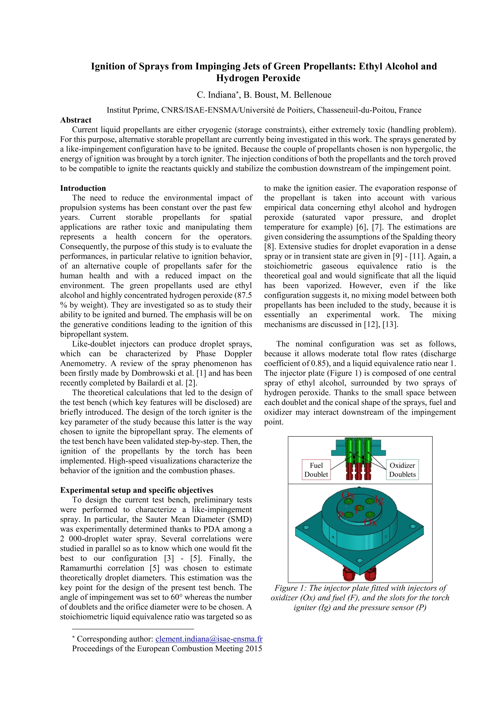
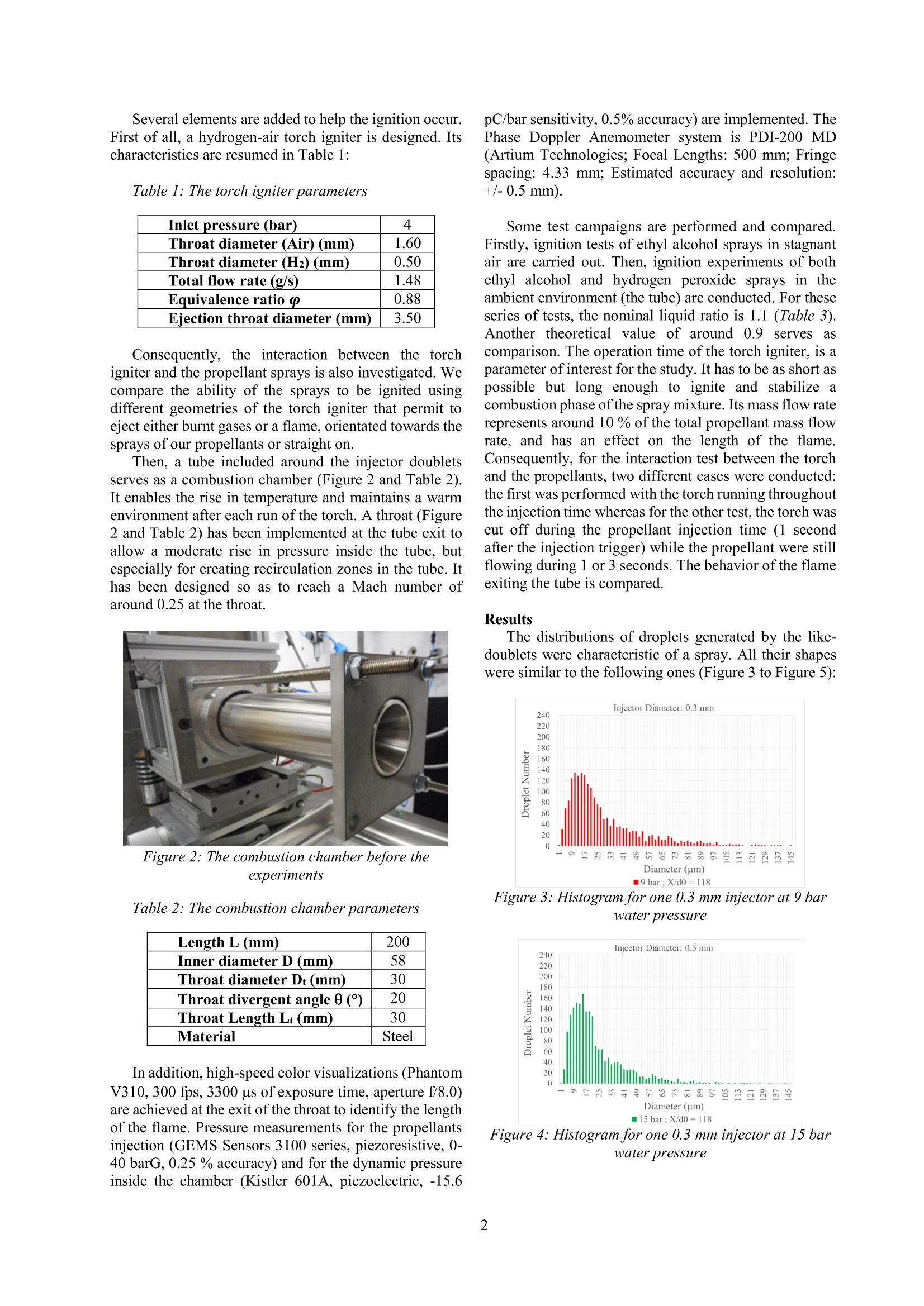
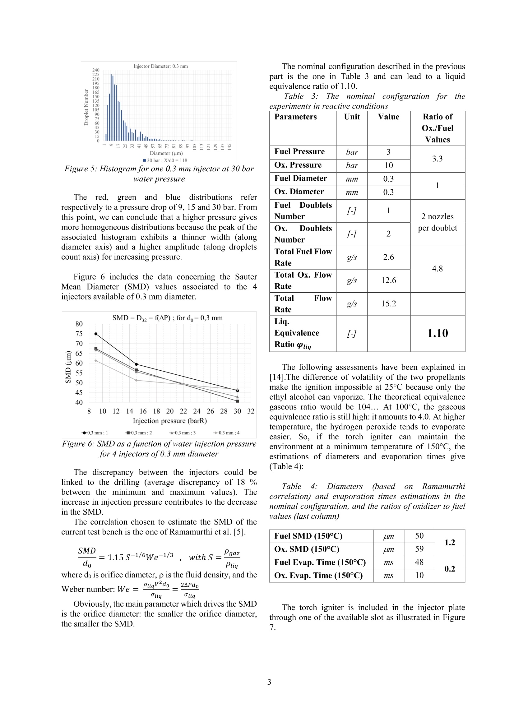
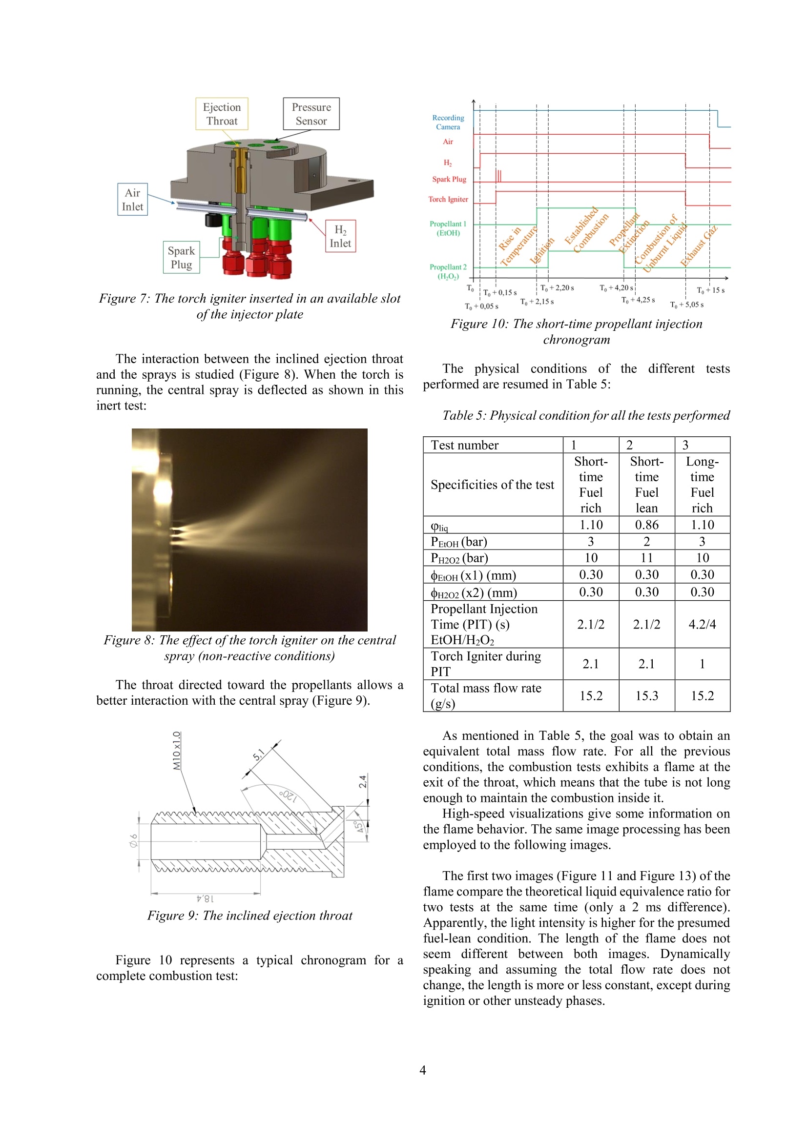
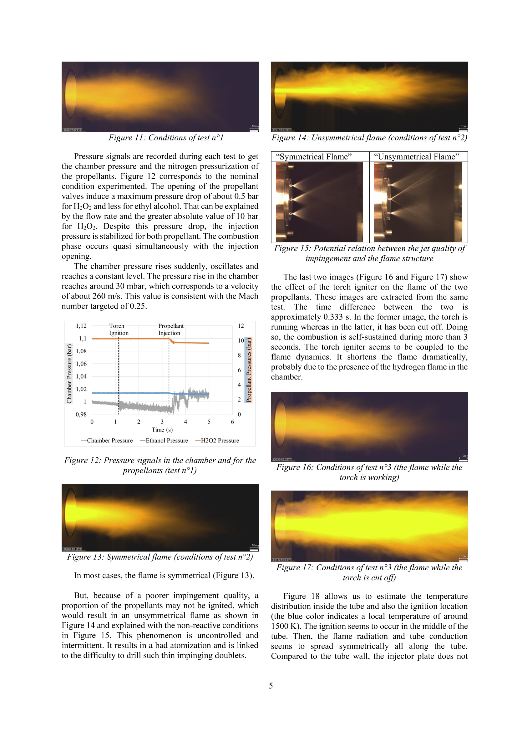
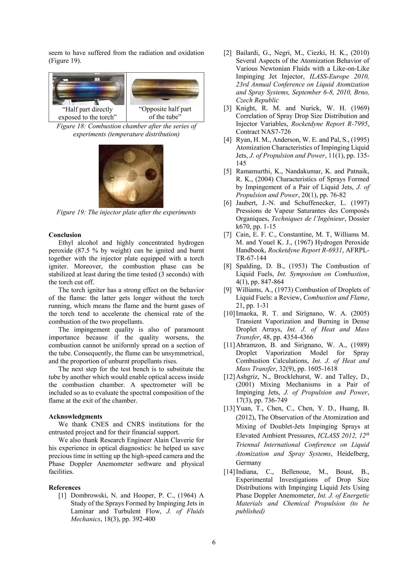
Ignition of Sprays from Impinging Jets of Green Propellants: Ethyl Alcohol andHydrogen Peroxide C. Indiana*, B. Boust, M. BellenoueInstitut Pprime, CNRS/ISAE-ENSMA/Universite de Poitiers, Chasseneuil-du-Poitou, France Abstract Current liquid propellants are either cryogenic (storage constraints), either extremely toxic (handling problem).For this purpose, alternative storable propellant are currently being investigated in this work. The sprays generated bya like-impingement configuration have to be ignited. Because the couple of propellants chosen is non hypergolic, theenergy ofignition was brought by a torch igniter. The injection conditions of both the propellants and the torch provedto be compatible to ignite the reactants quickly and stabilize the combustion downstream of the impingement point. Introduction The need to reduce the environmental impact ofpropulsion systems has been constant over the past fewyears. Current storable propellantsforspatialapplications are rather toxic and manipulating themrepresents a health concernfor the(operators.Consequently, the purpose of this study is to evaluate theperformances, in particular relative to ignition behavior,of an alternative couple of propellants safer for thehuman health andl with a reduced impact on theenvironment. The green propellants used are ethylalcohol and highly concentrated hydrogen peroxide (87.5% by weight). They are investigated so as to study theirability to be ignited and burned. The emphasis will be onthe generative conditions leading to the ignition of thisbipropellant system. Like-doublet injectors can produce droplet sprays,whichcanbecharacterized byPhase DopplerAnemometry. A review of the spray phenomenon hasbeen firstly made by Dombrowski et al. [1] and has beenrecently completed by Bailardi et al. [2]. The theoretical calculations that led to the design ofthe test bench (which key features will be disclosed) arebriefly introduced. The design of the torch igniter is thekey parameter of the study because this latter is the waychosen to ignite the bipropellant spray. The elements ofthe test bench have been validated step-by-step. Then, theignition of the propellants by the torch has beenimplemented. High-speed visualizations characterize thebehavior of the ignition and the combustion phases. Experimental setup and specific objectives To design the current test bench, preliminary testswere performed to characterize a like-impingementspray. In particular, the Sauter Mean Diameter (SMD)was experimentally determined thanks to PDA among a2 000-droplet water spray. Several correlations werestudied in parallel so as to know which one would fit thebest to our configurationn[3] - [5]. Finally, theRamamurthi correlation [5] was chosen to estimatetheoretically droplet diameters. This estimation was thekey point for the design of the present test bench. Theangle of impingement was set to 60° whereas the numberof doublets and the orifice diameter were to be chosen. Astoichiometric liquid equivalence ratio was targeted so as to make the ignition easier. The evaporation response ofthe propellant is taken into account with variousempirical data concerning ethyl alcohol and hydrogenperoxide(saturated vapor pressure, and droplettemperature for example) [6], [7]. The estimations aregiven considering the assumptions of the Spalding theory[8]. Extensive studies for droplet evaporation in a densespray or in transient state are given in [9]-[11]. Again, astoichiometricgaseouslseequivalence ratioisistthetheoretical goal and would significate that all the liquidhas been vaporized. However, even if the likeconfiguration suggests it, no mixing model between bothpropellants has been included to the study, because it isessentially anexperimentalwork. The mixingmechanisms are discussed in [12], [13]. The nominal configuration was set as follows,because it allows moderate total flow rates (dischargecoefficient of 0.85), and a liquid equivalence ratio near 1.The injector plate (Figure1) is composed of one centralspray of ethyl alcohol, surrounded by two sprays ofhydrogen peroxide. Thanks to the small space betweeneach doublet and the conical shape of the sprays, fuel andoxidizer may interact downstream of the impingementpoint. Figure 1: The injector plate fitted with injectors ofoxidizer (Ox) and fuel (F), and the slots for the torchigniter (Ig) and the pressure sensor (P) ( * Corresponding author: clement.indiana@isae-ensma.fr Proceedings of the European Combustion Meeting 2015 ) Several elements are added to help the ignition occur.First of all, a hydrogen-air torch igniter is designed. Itscharacteristics are resumed in Table 1: Table 1: The torch igniter parameters Inlet pressure (bar) 4 Throat diameter (Air) (mm) 1.60 Throat diameter (H2) (mm) 0.50 Total flow rate (g/s) 1.48 Equivalence ratio o 0.88 Ejection throat diameter (mm) 3.50 Consequently, the interaction between the torchigniter and the propellant sprays is also investigated. Wecompare the ability of the sprays to be ignited usingdifferent geometries of the torch igniter that permit toeject either burnt gases or a flame, orientated towards thesprays of our propellants or straight on. Then, a tube included around the injector doubletsserves as a combustion chamber (Figure 2 and Table 2).It enables the rise in temperature and maintains a warmenvironment after each run of the torch. A throat (Figure2 and Table 2) has been implemented at the tube exit toallow a moderate rise in pressure inside the tube, butespecially for creating recirculation zones in the tube. Ithas been designed so as to reach a Mach number ofaround 0.25 at the throat. Figure 2: The combustion chamber before theexperiments Table 2: The combustion chamber parameters Length L (mm) 200 Inner diameter D (mm) 58 Throat diameter Dt (mm) 30 Throat divergent angle 0() 20 Throat Length Lt (mm) 30 Material Steel In addition, high-speed color visualizations (PhantomV310, 300 fps, 3300 us of exposure time, aperture f/8.0)are achieved at the exit of the throat to identify the lengthof the flame. Pressure measurements for the propellantsinjection (GEMS Sensors 3100 series, piezoresistive, 0-40 barG, 0.25 % accuracy) and for the dynamic pressureinside the chamber (Kistler 601A, piezoelectric, -15.6 pC/bar sensitivity, 0.5% accuracy) are implemented. ThePhase Doppler Anemometer system is PDI-200 MD(Artium Technologies; Focal Lengths: 500 mm; Fringespacing: 4.33 mm; Estimated accuracy and resolution:+/-0.5 mm). Some test campaigns are performed and compared.Firstly, ignition tests of ethyl alcohol sprays in stagnantair are carried out. Then, ignition experiments of bothethyl alcohol and hydrogen peroxide sprays in theambient environment (the tube) are conducted. For theseseries of tests, the nominal liquid ratio is 1.1 (Table 3).Another theoretical value of around 0.9 serves ascomparison. The operation time of the torch igniter, is aparameter of interest for the study. It has to be as short aspossible but long enough to ignite and stabilize acombustion phase of the spray mixture.Its mass flow raterepresents around 10 % ofthe total propellant mass flowrate, and has an effect on the length of the flame.Consequently, for the interaction test between the torchand the propellants, two different cases were conducted:the first was performed with the torch running throughoutthe injection time whereas for the other test, the torch wascut off during the propellant injection time (1 secondafter the injection trigger) while the propellant were stillflowing during 1 or 3 seconds. The behavior of the flameexiting the tube is compared. Results The distributions of droplets generated by the like-doublets were characteristic of a spray. All their shapeswere similar to the following ones (Figure 3 to Figure 5): Figure 3: Histogram for one 0.3 mm injector at 9 barwater pressure Figure4: Histogram for one 0.3 mm injector at 15 barwater pressure Figure 5: Histogram for one 0.3 mm injector at 30 barwater pressure The red.,greenand(nbluetdistributions; referrespectively to a pressure drop of 9, 15 and 30 bar. Fromthis point, we can conclude that a higher pressure givesmore homogeneous distributions because the peak of theassociated histogram exhibits a thinner width (alongdiameter axis) and a higher amplitude (along dropletscount axis) for increasing pressure. Figure 6 includes the data concerning the SauterMean Diameter (SMD) values associated to the 4injectors available of 0.3 mm diameter. Figure 6: SMD as a function ofwater injection pressurefor 4 injectors of0.3 mm diameter The discrepancy between the injectors could belinked to the drilling (average discrepancy of 18 %between the minimum and maximum values). Theincrease in injection pressure contributes to the decreasein the SMD. The correlation chosen to estimate the SMD of thecurrent test bench is the one of Ramamurthi et al. [5]. where do is orifice diameter, p is the fluid density, and thePligv2do 2APdo Weber number:We=Oliq Oliq Obviously, the main parameter which drives the SMDis the orifice diameter: the smaller the orifice diameter,the smaller the SMD. The nominal configuration described in the previouspart is the one in Table 3 and can lead to a liquidequivalence ratio of 1.10. Table3 Thenominal configuration for theexperiments in reactive conditions Parameters Unit Value Ratio of Ox./FuelValues Fuel Pressure bar 3 3.3 Ox. Pressure bar 10 Fuel Diameter mm 0.3 1 Ox.Diameter mm 0.3 Fuel DoubletsNumber 1 2 nozzles per doublet Ox. DoubletsNumber [-] 2 Total Fuel FlowRate g/s 2.6 4.8 Total Ox. FlowRate g/s 12.6 Total FlowRate g/s 15.2 Liq.EquivalenceRatio Olig [-] 1.10 The following assessments have been explained in[14].The difference of volatility of the two propellantsmake the ignition impossible at 25℃ because only theethyl alcohol can vaporize. The theoretical equivalencegaseous ratio would be 104... At 100℃, the gaseousequivalence ratio is still high: it amounts to 4.0. At highertemperature, the hydrogen peroxide tends to evaporateeasier. So, if the torch igniter can maintain theenvironment at a minimum temperature of 150°C, theestimations of diameters and evaporation times give(Table 4): Table 4: Diameters (based(onRamamurthicorrelation) and evaporation times estimations in thenominal configuration, and the ratios ofoxidizer to fuelvalues (last column) Fuel SMD (150°C) uim 50 1.2 Ox. SMD (150°C) um 59 Fuel Evap. Time (150°C) ms 48 0.2 Ox. Evap. Time (150°C) 1s 10 The torch igniter is included in the injector platethrough one of the available slot as illustrated in Figure7. Figure 7: The torch igniter inserted in an available slotof the injector plate The interaction between the inclined ejection throatand the sprays is studied (Figure 8). When the torch isrunning, the central spray is deflected as shown in thisinert test: Figure 8: The effect of the torch igniter on the centralspray (non-reactive conditions) The throat directed toward the propellants allows abetter interaction with the central spray (Figure 9). Figure 9: The inclined ejection throat Figure 10 represents a typical chronogram for acomplete combustion test: Figure 10: The short-time propellant injectionchronogram The physical conditions of thee differenttestsperformed are resumed in Table 5: Table 5: Physical condition for all the tests performed Test number 1 2 3 Specificities of the test Short-timeFuelrich Short-timeFuellean Long-timeFuelrich Olig 1.10 0.86 1.10 PEtoH (bar) 3 2 3 PH202 (bar) 10 11 10 EtoH(x1) (mm) 0.30 0.30 0.30 QH202 (x2) (mm) 0.30 0.30 0.30 Propellant InjectionTime (PIT) (s) EtOH/HO, 2.1/2 2.1/2 4.2/4 Torch Igniter duringPIT 2.1 2.1 1 Total mass flow rate(g/s) 15.2 15.3 15.2 As mentioned in Table 5, the goal was to obtain anequivalent total mass flow rate. For all the previousconditions, the combustion tests exhibits a flame at theexit of the throat, which means that the tube is not longenough to maintain the combustion inside it. High-speed visualizations give some information onthe flame behavior. The same image processing has beenemployed to the following images. The first two images (Figure 11 and Figure 13) of theflame compare the theoretical liquid equivalence ratio fortwo tests at the same time (only a 2 ms difference).Apparently, the light intensity is higher for the presumedfuel-lean condition. The length of the flame does notseem different between both images. Dynamicallyspeaking and assuming the total flow rate does notchange, the length is more or less constant, except duringignition or other unsteady phases. Figure 11: Conditions of test n°1 Pressure signals are recorded during each test to getthe chamber pressure and the nitrogen pressurization ofthepropellants. Figure 12 corresponds to the nominalcondition experimented. The opening of the propellantvalves induce a maximum pressure drop of about 0.5 barfor H2O2 and less for ethyl alcohol. That can be explainedby the flow rate and the greater absolute value of 10 barfor H202. Despite this pressure drop, the injectionpressure is stabilized for both propellant. The combustionphase occurs quasi simultaneously with the injectionopening. The chamber pressure rises suddenly, oscillates andreaches a constant level. The pressure rise in the chamberreaches around 30 mbar, which corresponds to a velocityof about 260 m/s. This value is consistent with the Machnumber targeted of0.25. Figure 12: Pressure signals in the chamber and for thepropellants (test n°l) Figure 13: Symmetrical flame (conditions oftest n°2) In most cases, the flame is symmetrical (Figure 13). But, because of a poorer impingement quality, aproportion of the propellants may not be ignited, whichwould result in an unsymmetrical flame as shown inFigure 14 and explained with the non-reactive conditionsin Figure 15. This phenomenon is uncontrolled andintermittent. It results in a bad atomization and is linkedto the difficulty to drill such thin impinging doublets. Figure 14: Unsymmetrical flame (conditions oftest n°2) Figure 15: Potential relation between the jet quality ofimpingement and the flame structure The last two images (Figure 16 and Figure 17) showthe effect of the torch igniter on the flame of the twopropellants. These images are extracted from the sametest. The time difference between the twop isapproximately 0.333 s. In the former image, the torch isrunning whereas in the latter, it has been cut off. Doingso, the combustion is self-sustained during more than 3seconds. The torch igniter seems to be coupled to theflame dynamics. It shortens the flame dramatically,probably due to the presence of the hydrogen flame in thechamber. Figure 16: Conditions oftest n°3 (the flame while thetorch is working) Figure 17: Conditions oftest n°3 (the flame while thetorch is cut off) Figure 18 allows us to estimate the temperaturedistribution inside the tube and also the ignition location(the blue color indicates a local temperature of around1500 K). The ignition seems to occur in the middle of thetube. Then, the flame radiation and tube conductionseems to spread symmetrically all along the tube.Compared to the tube wall, the injector plate does not seem to have suffered from the radiation and oxidation(Figure 19). Figure 19: The injector plate after the experiments Conclusion Ethyl alcohol and highly concentrated hydrogenperoxide (87.5 % by weight) can be ignited and burnttogether with the injector plate equipped with a torchigniter. Moreover, the combustion phase can bestabilized at least during the time tested (3 seconds) withthe torch cut off. The torch igniter has a strong effect on the behaviorof the flame: the latter gets longer without the torchrunning, which means the flame and the burnt gases ofthe torch tend to accelerate the chemical rate of thecombustion of the two propellants. The impingement quality is also of paramountimportancebecauseif theq ugalityworsens. thecombustion cannot be uniformly spread on a section ofthe tube. Consequently, the flame can be unsymmetrical,and the proportion of unburnt propellants rises. The next step for the test bench is to substitute thetube by another which would enable optical access insidethe combustion chamber. Aspectrometer will beincluded so as to evaluate the spectral composition oftheflame at the exit of the chamber. Acknowledgments We thank CNES and CNRS institutions for theentrusted project and for their financial support. We also thank Research Engineer Alain Claverie forhis experience in optical diagnostics: he helped us saveprecious time in setting up the high-speed camera and thePhase Doppler Anemometer software and physicalfacilities. References ( [1] Dombrowski, N. and H o oper, P . C . , (1964) AStudy of the Sprays F ormed by Impinging Jets inLaminar and T urbulent F low, J . o f FluidsMechanics,18(3), pp. 392-400 ) [2] Bailardi, G., Negri, M., Ciezki, H. K., (2010)Several Aspects of the Atomization Behavior ofVarious Newtonian Fluids with a Like-on-LikeImpinging Jet Injector,ILASS-Europe 2010,23rd Annual Conference on Liquid Atomizationand Spray Systems, September 6-8, 2010, Brno,Czech Republic [3] Knight, R. M. and Nurick, W. H. (1969)Correlation of Spray Drop Size Distribution andInjector Variables, Rocketdyne Report R-7995,Contract NAS7-726 [4]Ryan, H. M., Anderson, W.E. and Pal,S., (1995)Atomization Characteristics of Impinging LiquidJets,J. ofPropulsion and Power, 11(1), pp. 135-145 5Ramamurthi, K., Nandakumar, K. and Patnaik,R. K., (2004) Characteristics of Sprays Formedby Impingement of a Pair of Liquid Jets, J. ofPropulsion and Power, 20(1), pp. 76-82 [6].Jaubert, J.-N. and Schuffenecker, L. (1997)Pressions de Vapeur Saturantes des ComposesOrganiques, Techniques de l'Ingenieur, Dossierk670,pp. 1-15 ( [7 ] Cain, E. F . C., Constantine, M. T , Williams M.M. and Youel K . J., ( 1967) Hydrogen Peroxide Handbook, Rocketdyne Report R-6931, AFRPL-TR-67-144 ) 81Spalding, D. B., (1953) The Combustion ofLiquid Fuels, Int. Symposium on Combustion,4(1),pp. 847-864 ( [9 ]W illiams, A., ( 1 973) Combustion o f Droplets of Liquid Fuels: a Review, Combustion and Flame, 2 1, pp. 1-31 ) ( [10]Imaoka, R . T. a nd Sirignano, W . A . ( 2 0 05) T ransient Vaporization and Burning in DenseDroplet Arrays, Int . J . of Hea t and Mass Transfer, 48, pp.4354-4366 ) ( [11]Abramzon, B . a nd S irignano, W. A ., (1989) Droplet V a porization M odel for Spray Combustion C a lculations, I nt. J. of Heat a nd Mass Transfer, 32(9), pp. 1605-1618 ) ( [12]Ashgriz, N ., B rocklehurst, W . a n d Talley, D.,(2001) Mixing Mechanisms i n a a P air ofImpinging Jets, J. of P ropulsion and P o wer, 1 7(3), pp. 736-749 ) ( [13]Yuan, T., Chen, C., Chen, Y. D., Huang, B.(2012), The Observation o f the Atomization a n d Mixing o f D o ublet-Jets Impinging S p rays a t Elevated Ambient Pressures, ICLASS 2012, 1 2 th Triennal International Conference on LiquidAtomization and S pray Systems, H eidelberg, Germany ) [14]Indiana,(C.,Bellenoue. M.,Boust.,B..Experimental IInvestigations of DropSizeDistributions with Impinging Liquid Jets UsingPhase Doppler Anemometer, Int. J. of EnergeticMaterials andChemicalPropulsion(toobepublished)
确定
还剩4页未读,是否继续阅读?

产品配置单


北京欧兰科技发展有限公司为您提供《乙醇和过氧化氢,绿色推进剂中速度,粒径检测方案(气溶胶)》,该方案主要用于其他中速度,粒径检测,参考标准--,《乙醇和过氧化氢,绿色推进剂中速度,粒径检测方案(气溶胶)》用到的仪器有Artium PDI-FP 双量程可机载飞行探头、激光相位多普勒干涉仪LDV,PDI,PDPA,PDA、激光诱导白炽光(LII)烟气分析仪
推荐专场


相关方案
更多
该厂商其他方案
更多