


方案详情
文
Nordson DAGE 研发了一种独一无二的专利技术,用于将测试探头连接到焊球或焊板,以便可以完全遵照新近发布的 IPC-9708 测试标准来执行热拔球测试,以便用于检测表面贴装和印刷电路板装配中是否存在焊盘坑裂。
方案详情

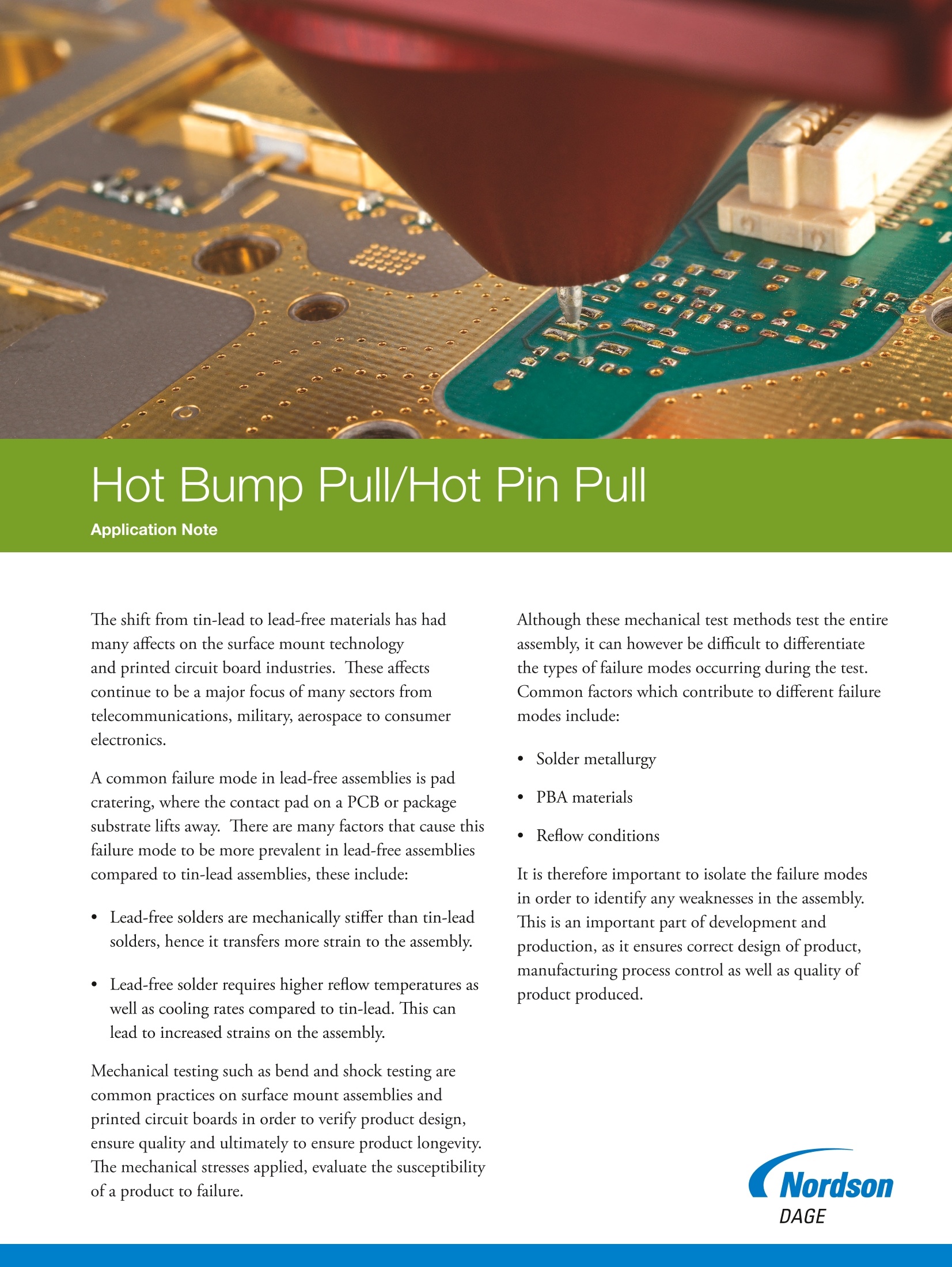
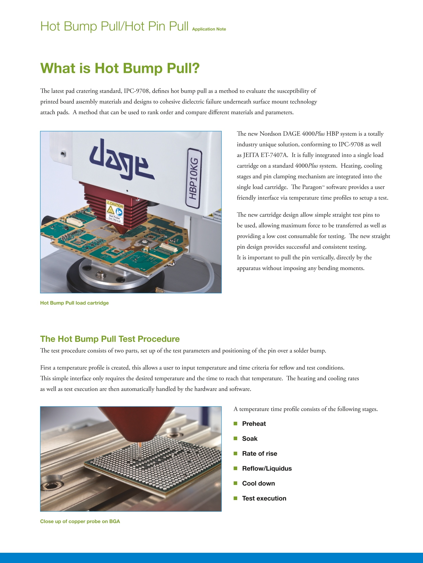
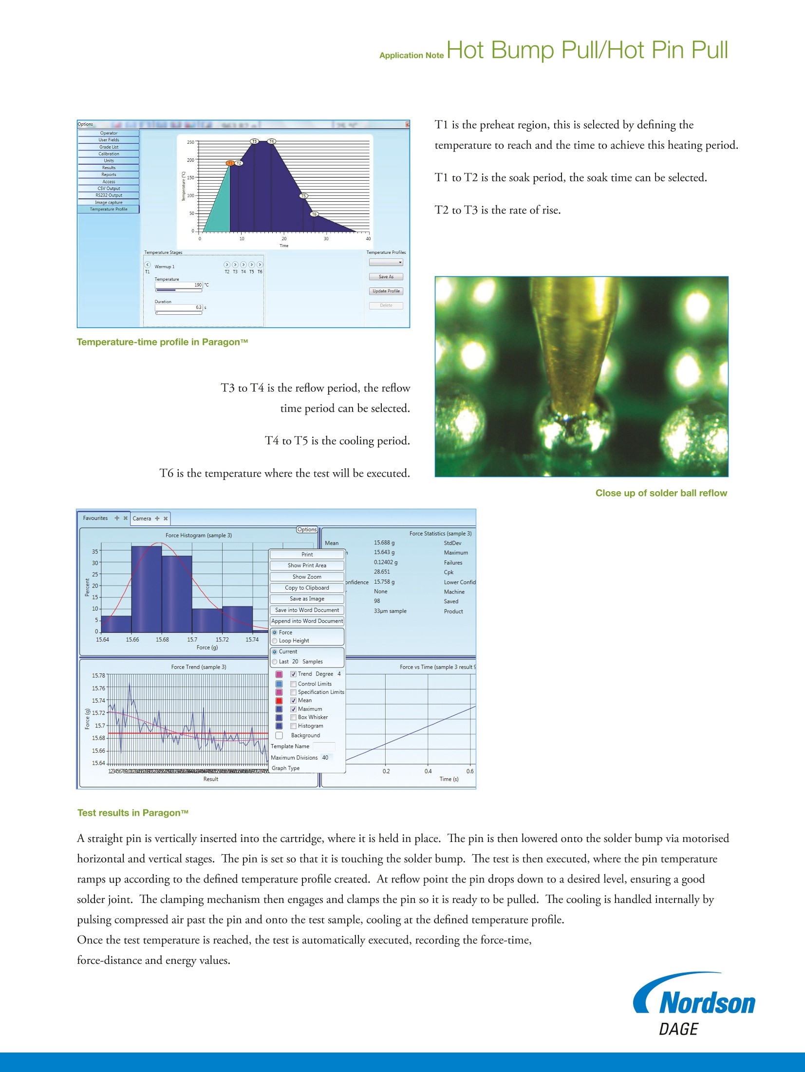
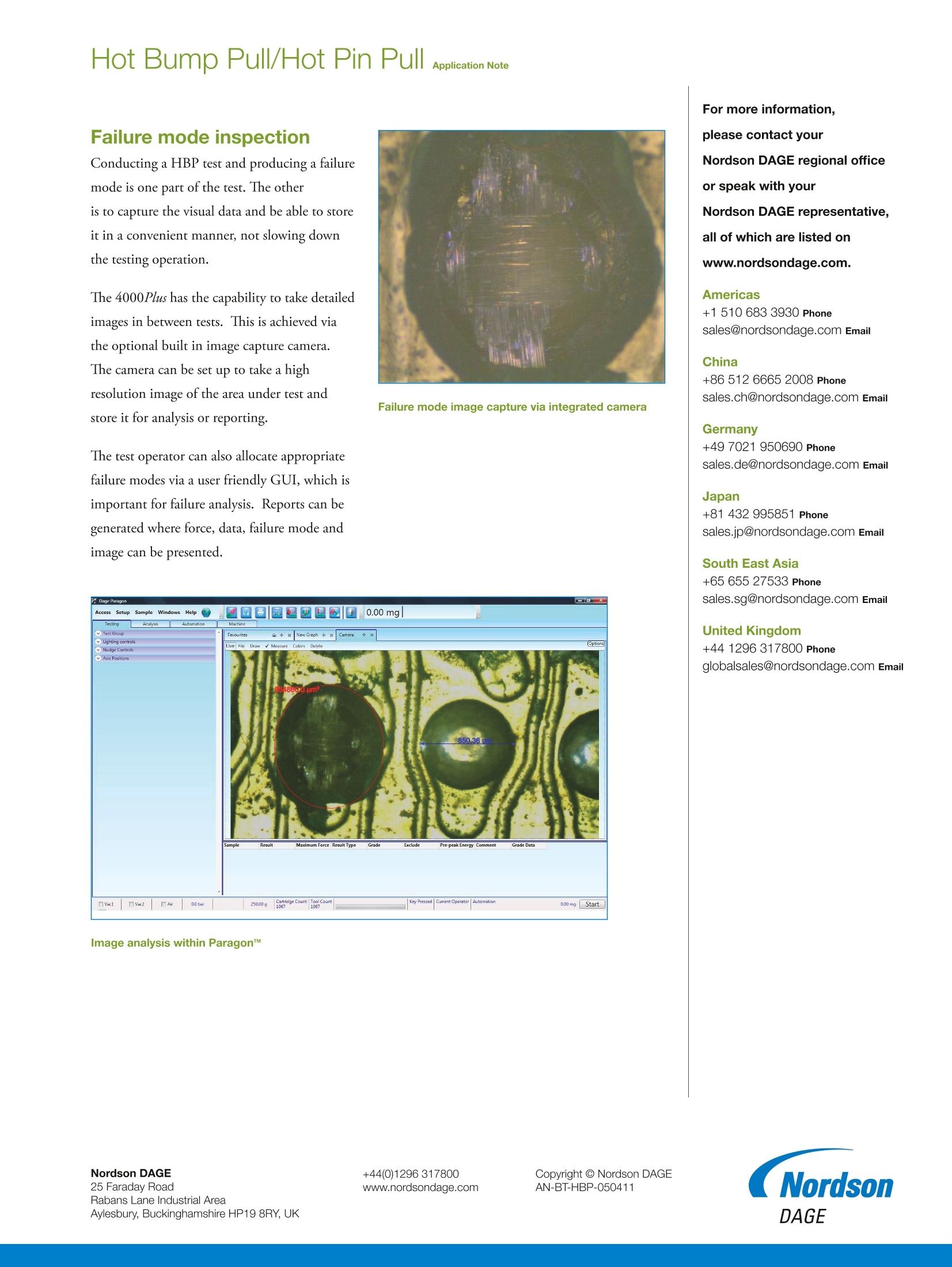
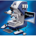
Application NoteHot Bump Pull/Hot Pin Pull Hot Bump Pull/Hot Pin Pull wApplication Note Hot Bump Pull/Hot Pin Pull The shift from tin-lead to lead-free materials has hadmany affects on the surface mount technologyand printed circuit board industries. These affectscontinue to be a major focus of many sectors fromtelecommunications, military, aerospace to consumerelectronics. A common failure mode in lead-free assemblies is padcratering, where the contact pad on a PCB or packagesubstrate lifts away. There are many factors that cause thisfailure mode to be more prevalent in lead-free assembliescompared to tin-lead assemblies, these include: · Lead-free solders are mechanically stiffer than tin-leadsolders, hence it transfers more strain to the assembly. Lead-free solder requires higher reflow temperatures aswell as cooling rates compared to tin-lead. This canlead to increased strains on the assembly. Mechanical testing such as bend and shock testing arecommon practices on surface mount assemblies andprinted circuit boards in order to verify product design,ensure quality and ultimately to ensure product longevity.The mechanical stresses applied, evaluate the susceptibilityof a product to failure. Although these mechanical test methods test the entireassembly, it can however be difficult to differentiatethe types of failure modes occurring during the test.Common factors which contribute to different failuremodes include: 自Solder metallurgy PBA materials Reflow conditions It is therefore important to isolate the failure modesin order to identify any weaknesses in the assembly.This is an important part of development andproduction, as it ensures correct design of product,manufacturing process control as well as quality ofproduct produced. Hot Bump Pull/Hot Pin Pull aApplication Note What is Hot Bump Pull? The latest pad cratering standard, IPC-9708, defines hot bump pull as a method to evaluate the susceptibility ofprinted board assembly materials and designs to cohesive dielectric failure underneath surface mount technologyattach pads. A method that can be used to rank order and compare different materials and parameters. The new Nordson DAGE 4000Plus HBP system is a totallyindustry unique solution, conforming to IPC-9708 as wellas JEITA ET-7407A. It is fully integrated into a single loadcartridge on a standard 4000Plus system. Heating, coolingstages and pin clamping mechanism are integrated into thesingle load cartridge. The Paragon"software provides a userfriendly interface via temperature time profiles to setup a test. The new cartridge design allow simple straight test pins tobe used, allowing maximum force to be transferred as well asproviding a low cost consumable for testing. The new straightpin design provides successful and consistent testing.It is important to pull the pin vertically, directly by theapparatus without imposing any bending moments. The Hot Bump Pull Test Procedure The test procedure consists of two parts, set up of the test parameters and positioning of the pin over a solder bump. First a temperature profile is created, this allows a user to input temperature and time criteria for reflow and test conditions.This simple interface only requires the desired temperature and the time to reach that temperature. The heating and cooling ratesas well as test execution are then automatically handled by the hardware and software. A temperature time profile consists of the following stages. Preheat Soak Rate of rise Reflow/Liquidus Cool down ■Test execution T1 is the preheat region, this is selected by defining thetemperature to reach and the time to achieve this heating period. T1 to T2 is the soak period, the soak time can be selected. T2 to T3 is the rate of rise. Temperature-time profile in ParagonTM T3 to T4 is the reflow period, the reflowtime period can be selected. T4 to T5 is the cooling period. T6 is the temperature where the test will be executed. Close up of solder ball reflow Test results in ParagonTM A straight pin is vertically inserted into the cartridge, where it is held in place. The pin is then lowered onto the solder bump via motorisedhorizontal and vertical stages. The pin is set so that it is touching the solder bump. The test is then executed, where the pin temperatureramps up according to the defined temperature profile created. At reflow point the pin drops down to a desired level, ensuring a goodsolder joint. The clamping mechanism then engages and clamps the pin so it is ready to be pulled. The cooling is handled internally bypulsing compressed air past the pin and onto the test sample, cooling at the defined temperature profile. Once the test temperature is reached, the test is automatically executed, recording the force-time,force-distance and energy values. DAGE Failure mode inspection Conducting a HBP test and producing a failuremode is one part of the test. The otheris to capture the visual data and be able to storeit in a convenient manner, not slowing downthe testing operation. The 4000Plus has the capability to take detailedimages in between tests. This is achieved viathe optional built in image capture camera.The camera can be set up to take a highresolution image of the area under test andstore it for analysis or reporting. Failure mode image capture via integrated camera The test operator can also allocate appropriatefailure modes via a user friendly GUI, which isimportant for failure analysis. Reports can begenerated where force, data, failure mode andimage can be presented. Close up of copper probe on BGA +ww.nordsondage.comCopyright C Nordson DAGEAN-BT-HBP-Faraday RoadRabans Lane Industrial AreaAylesbury, Buckinghamshire HPY, UK The shift from tin-lead to lead-free materials has had many affects on the surface mount technology and printed circuit board industries. These affects continue to be a major focus of many sectors from telecommunications, military, aerospace to consumer electronics.A common failure mode in lead-free assemblies is pad cratering, where the contact pad on a PCB or package substrate lifts away. There are many factors that cause this failure mode to be more prevalent in lead-free assemblies compared to tin-lead assemblies, these include:• Lead-free solders are mechanically stiffer than tin-lead solders, hence it transfers more strain to the assembly.• Lead-free solder requires higher reflow temperatures as well as cooling rates compared to tin-lead. This can lead to increased strains on the assembly.Mechanical testing such as bend and shock testing are common practices on surface mount assemblies and printed circuit boards in order to verify product design, ensure quality and ultimately to ensure product longevity. The mechanical stresses applied, evaluate the susceptibility of a product to failure.Although these mechanical test methods test the entire assembly, it can however be difficult to differentiate the types of failure modes occurring during the test. Common factors which contribute to different failure modes include:• Solder metallurgy• PBA materials• Reflow conditionsIt is therefore important to isolate the failure modes in order to identify any weaknesses in the assembly. This is an important part of development and production, as it ensures correct design of product, anufacturing process control as well as quality of product produced.
确定
还剩2页未读,是否继续阅读?

产品配置单

聚擘国际贸易(上海)有限公司为您提供《印刷电路板或包底物中热撞拉/热针检测方案(半导体检测仪)》,该方案主要用于其他中热撞拉/热针检测,参考标准--,《印刷电路板或包底物中热撞拉/热针检测方案(半导体检测仪)》用到的仪器有诺信达格Nordson DAGE多功能推拉力测试机DAGE4000Plus、DAGE4000Plus多功能推拉力测试机、DAGE4000Plus多功能推拉力测试机
推荐专场
相关方案
更多
该厂商其他方案
更多