


方案详情
文
PIV技术是测量研究高温喷射流体的有效方法。PIV技术需要示踪粒子。许多常规生成粒子的方法对高温喷射流体并不适用。本文介绍了制备和播撒均匀的亚微米粒子技术途径。
方案详情

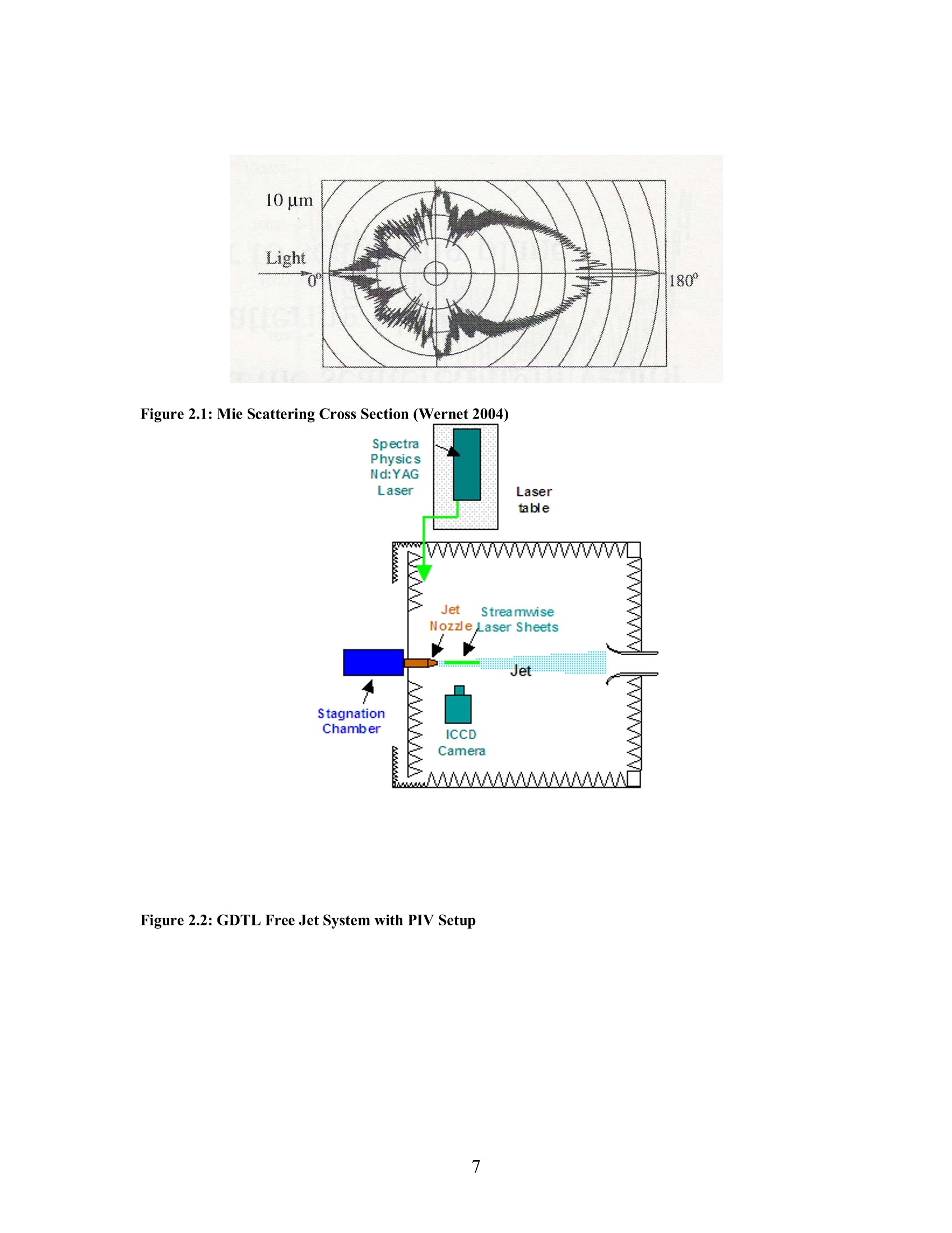
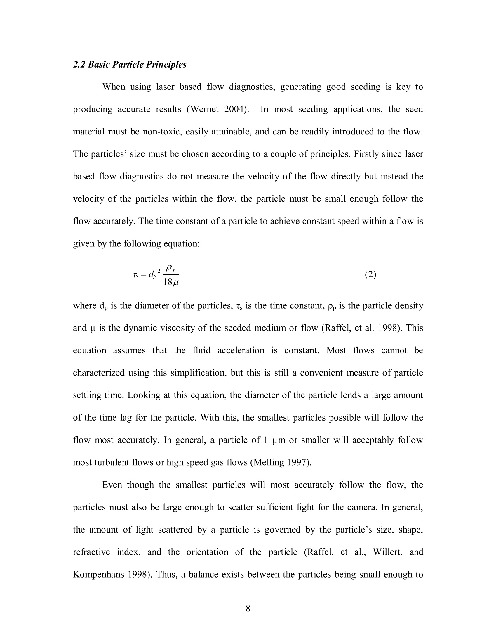
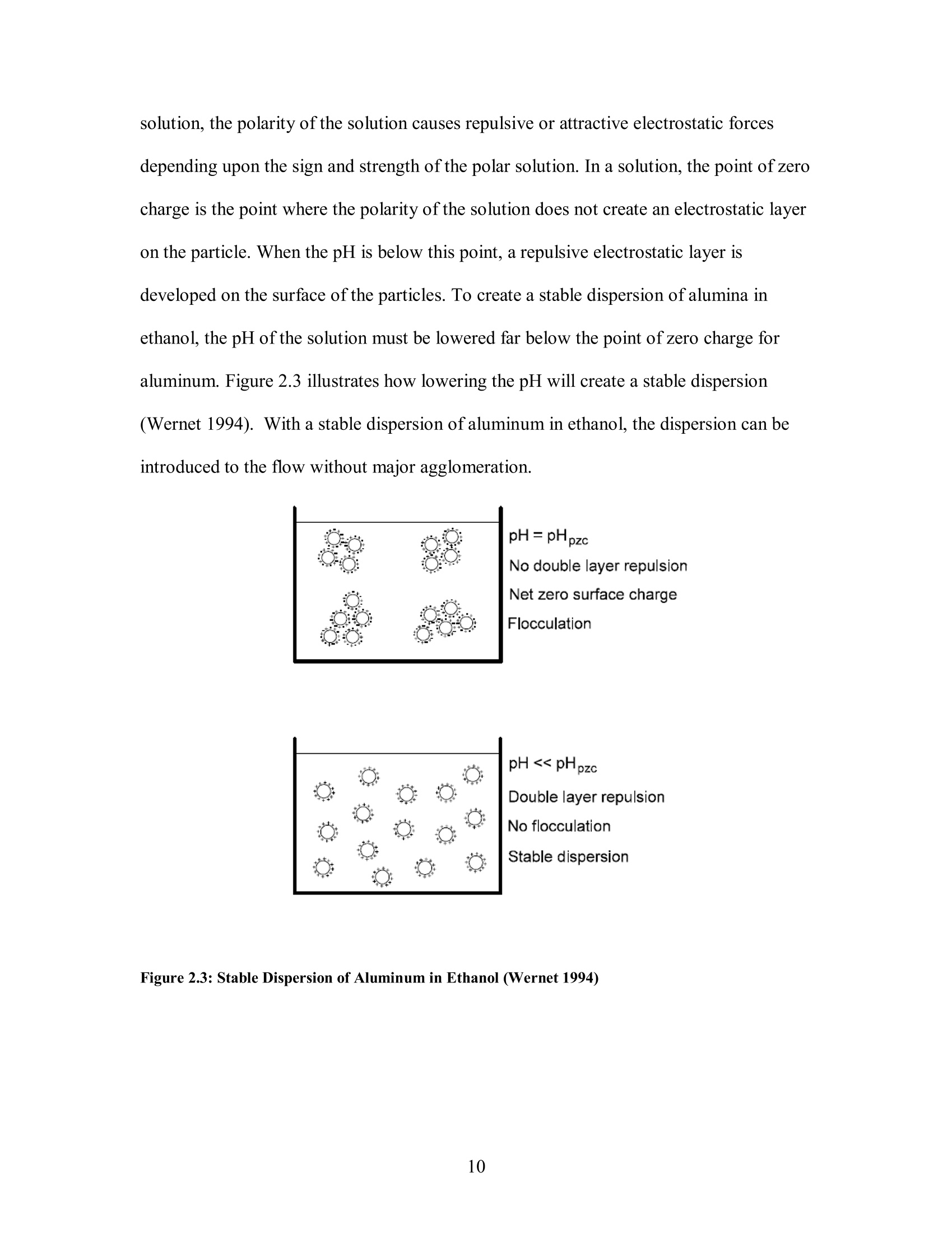
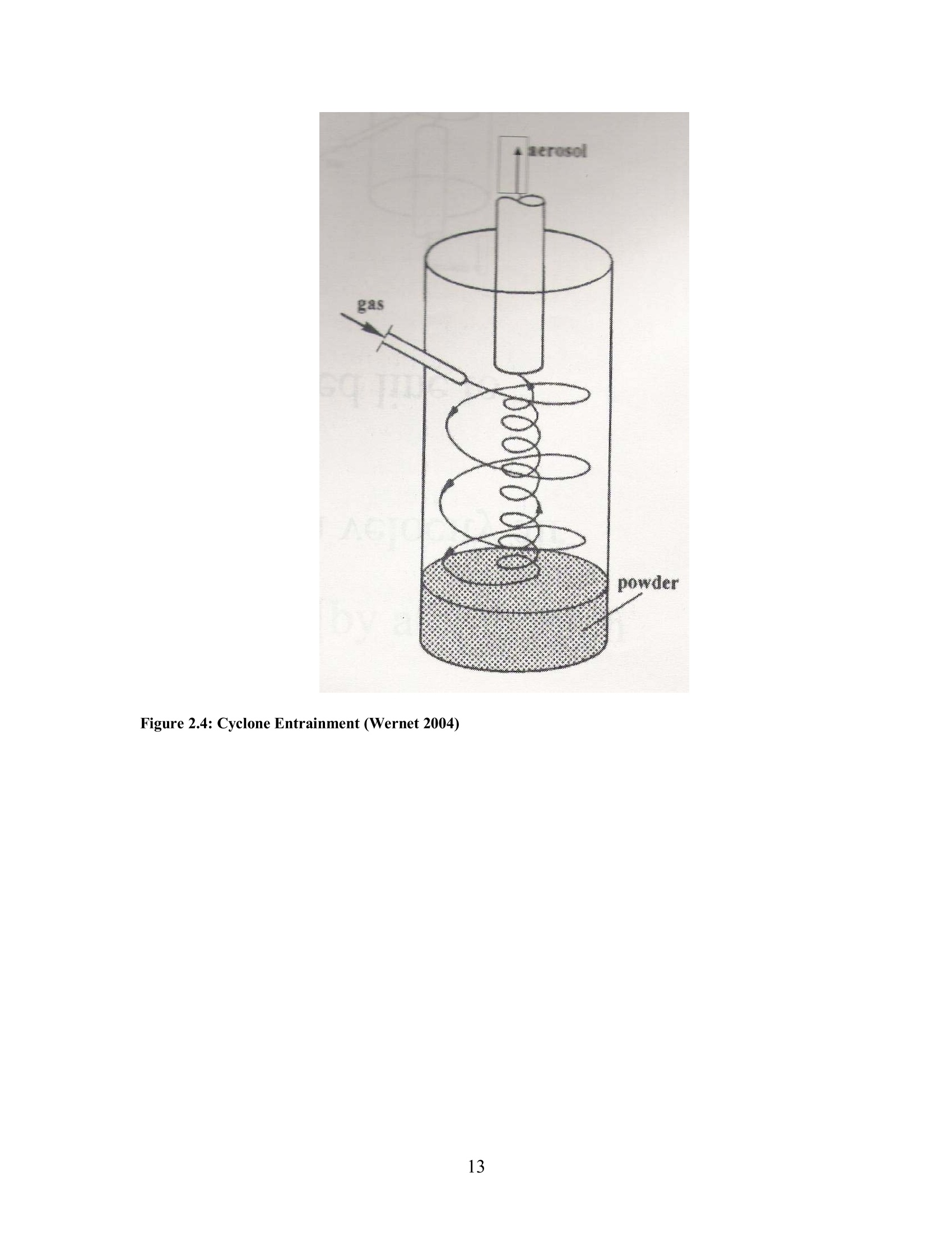
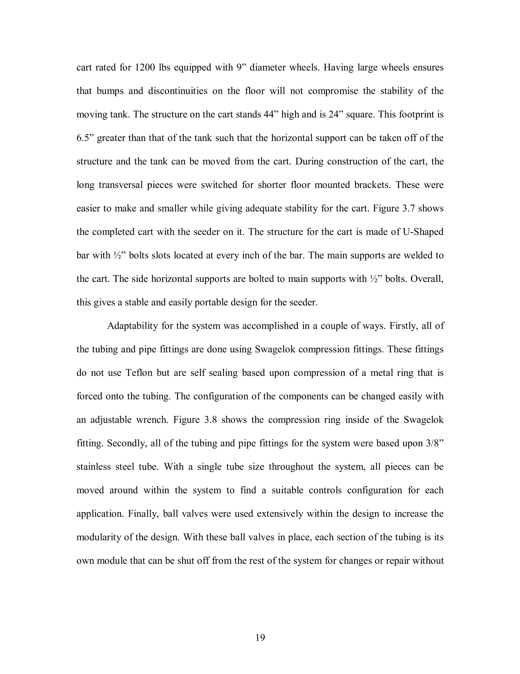
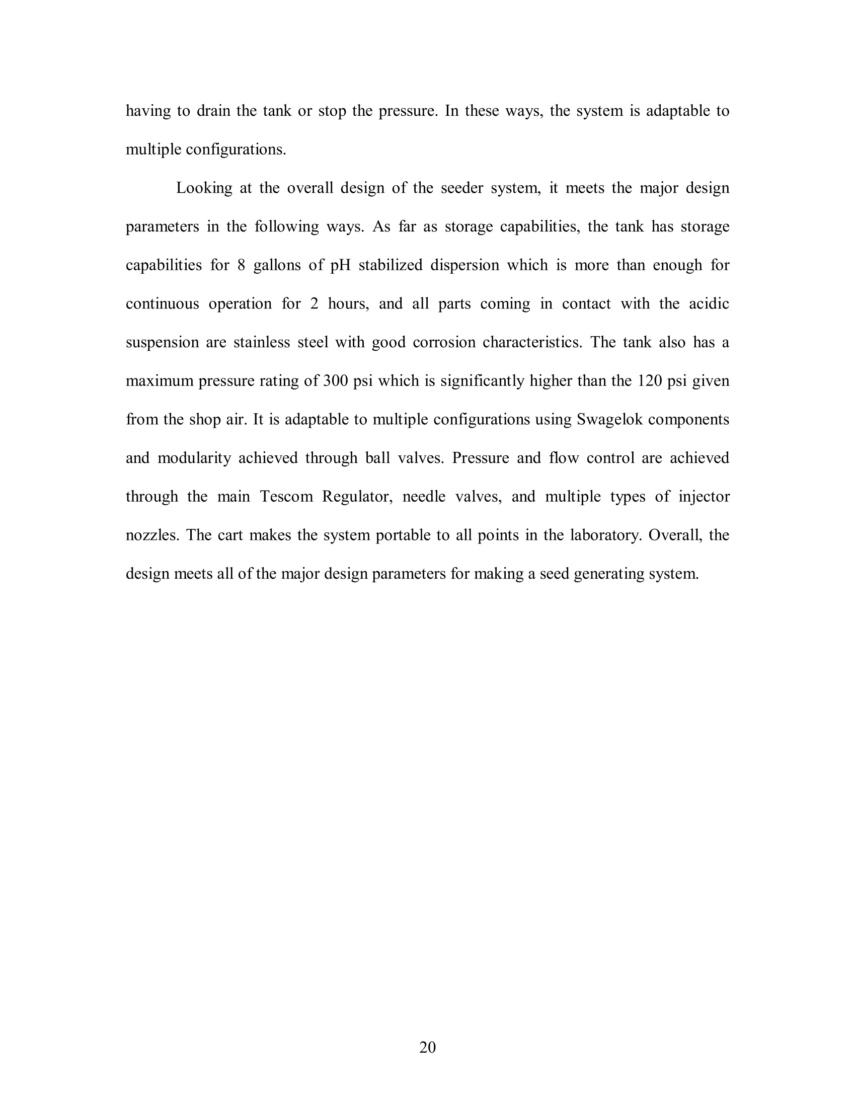
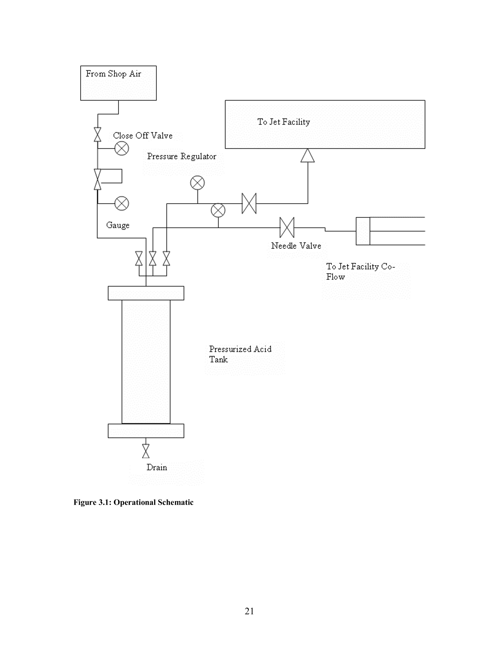
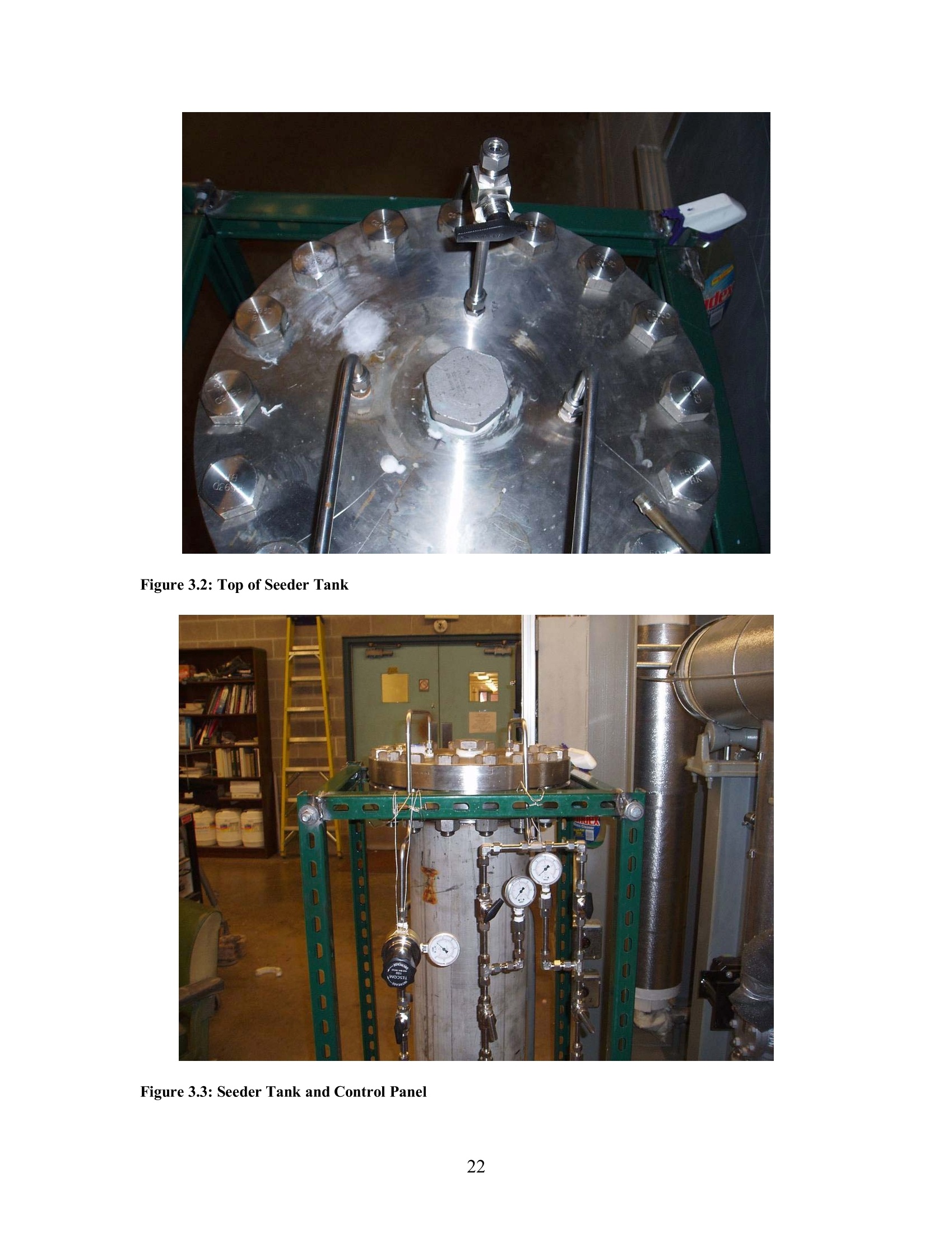
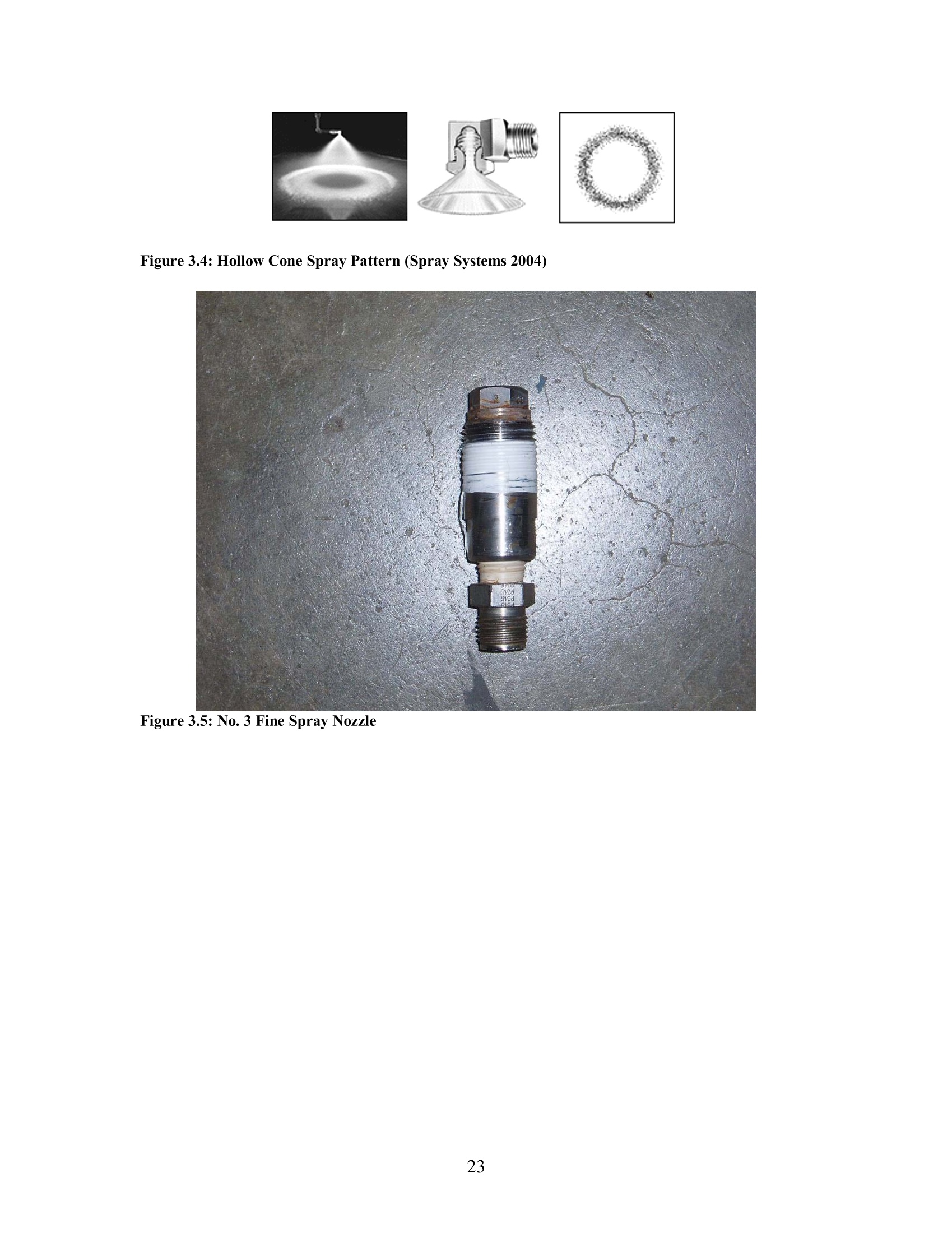
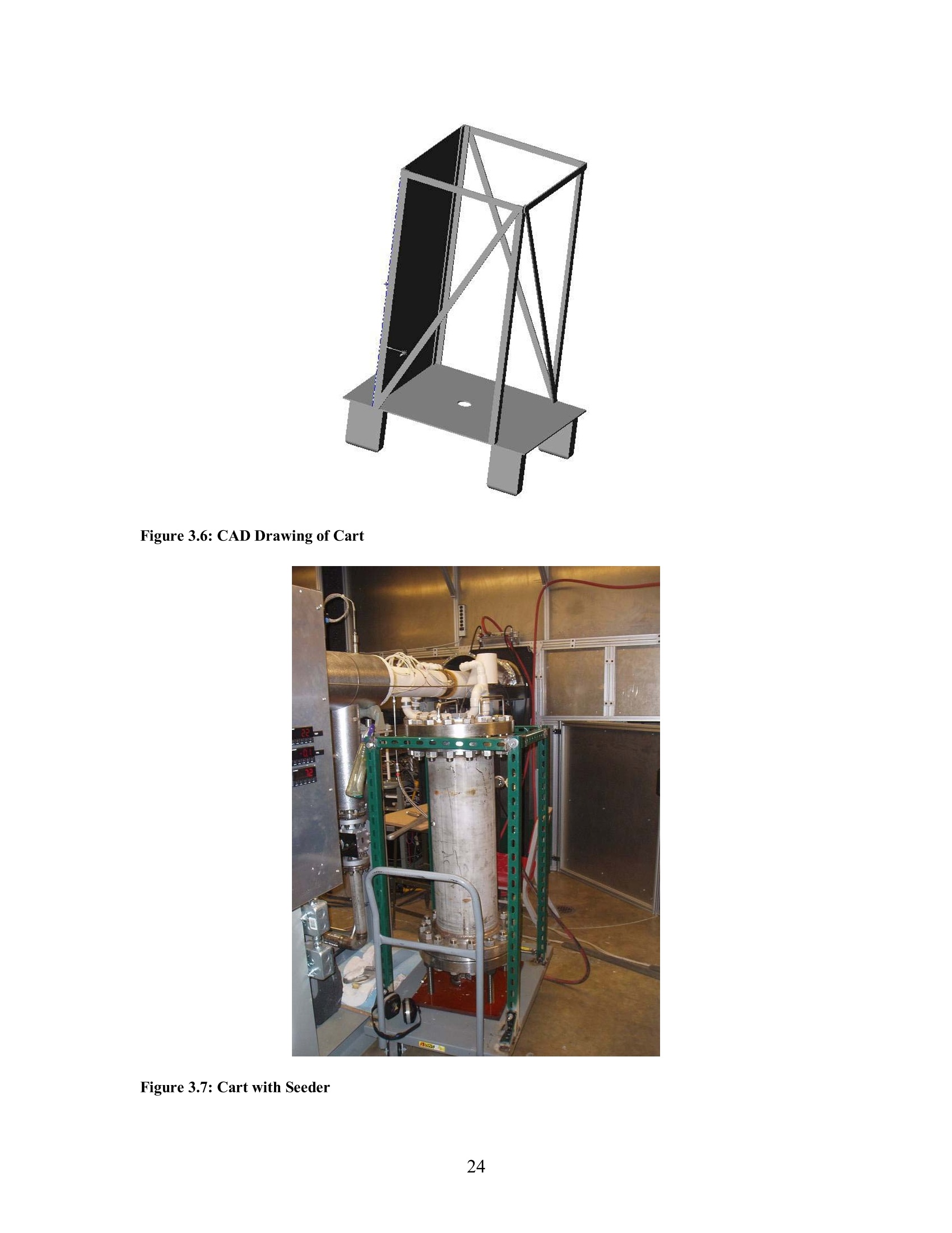
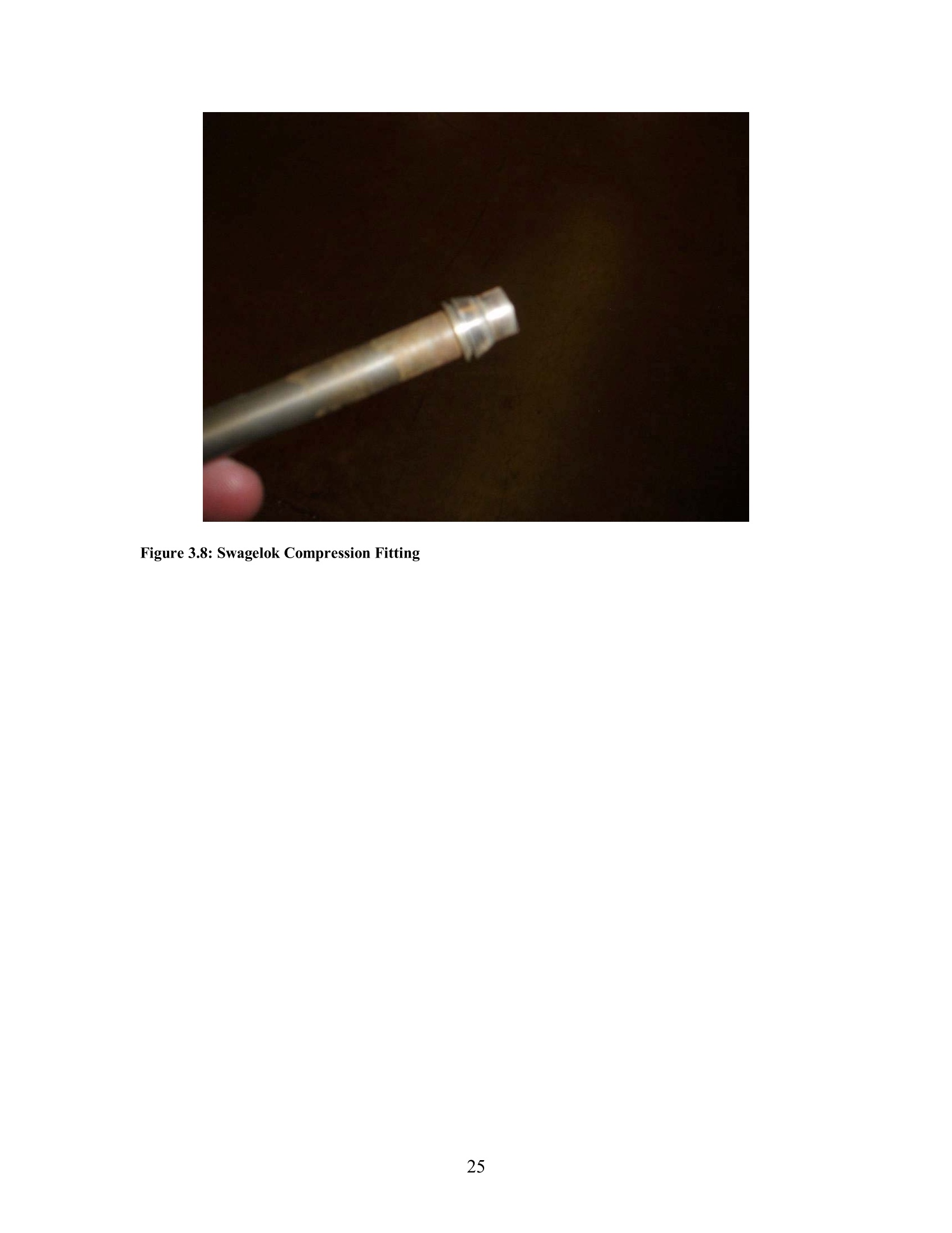
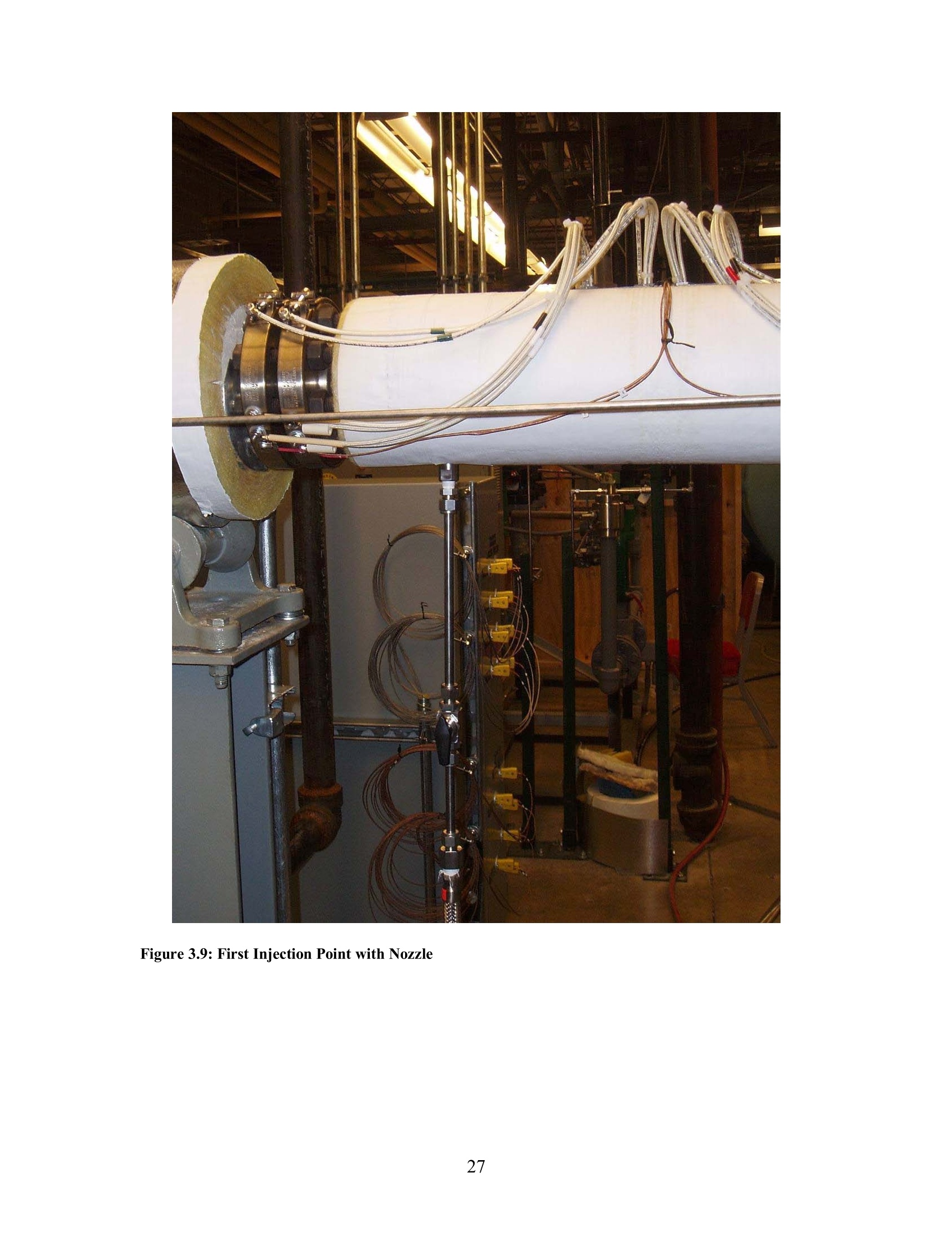
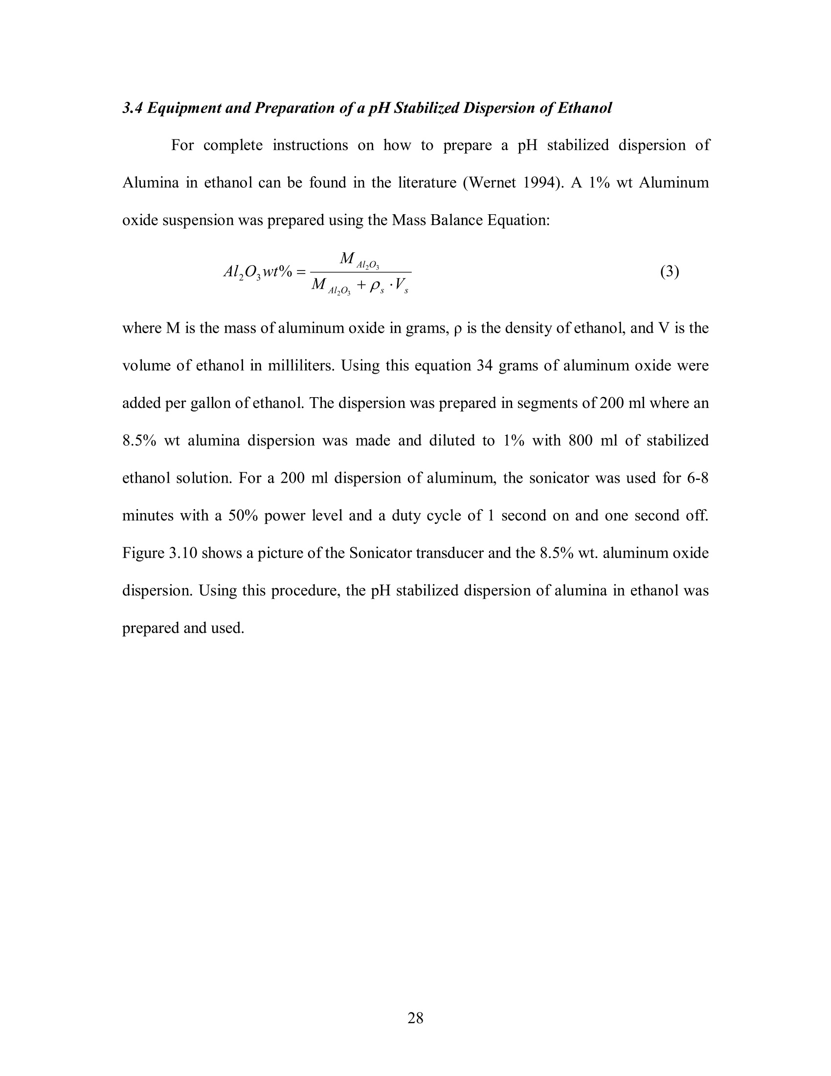
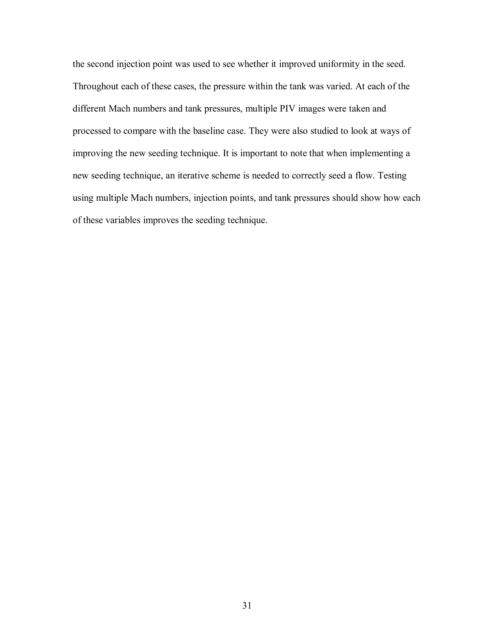
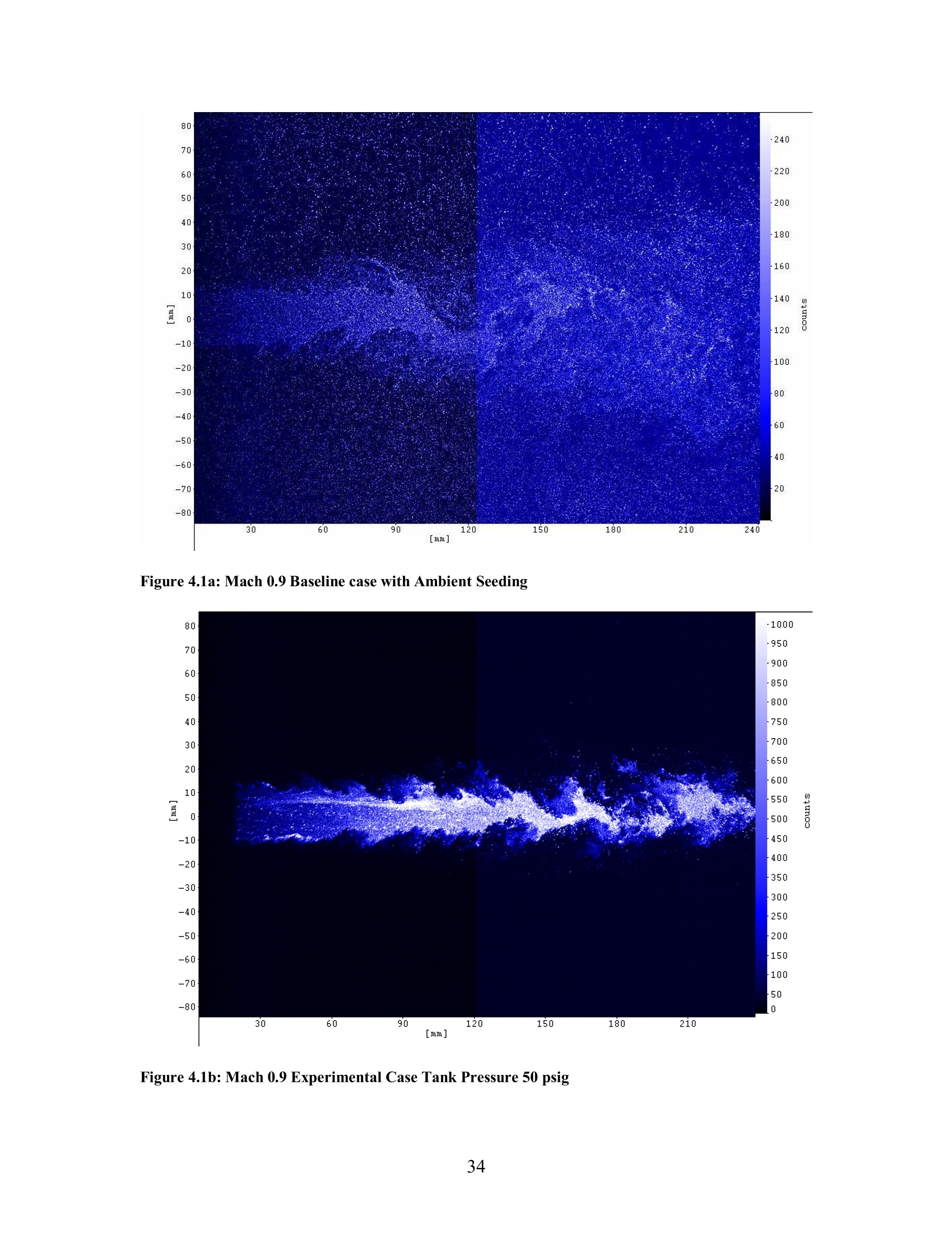
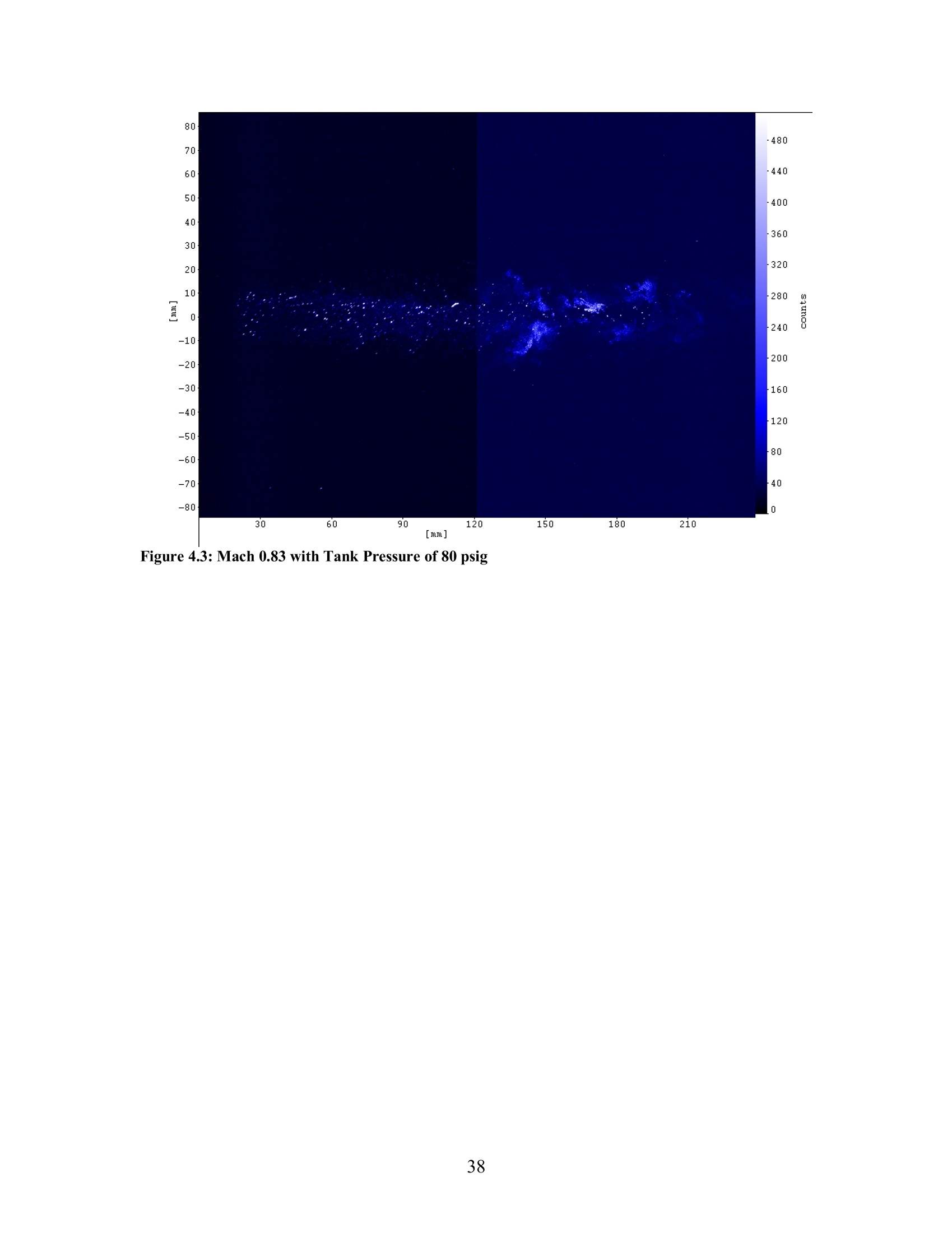
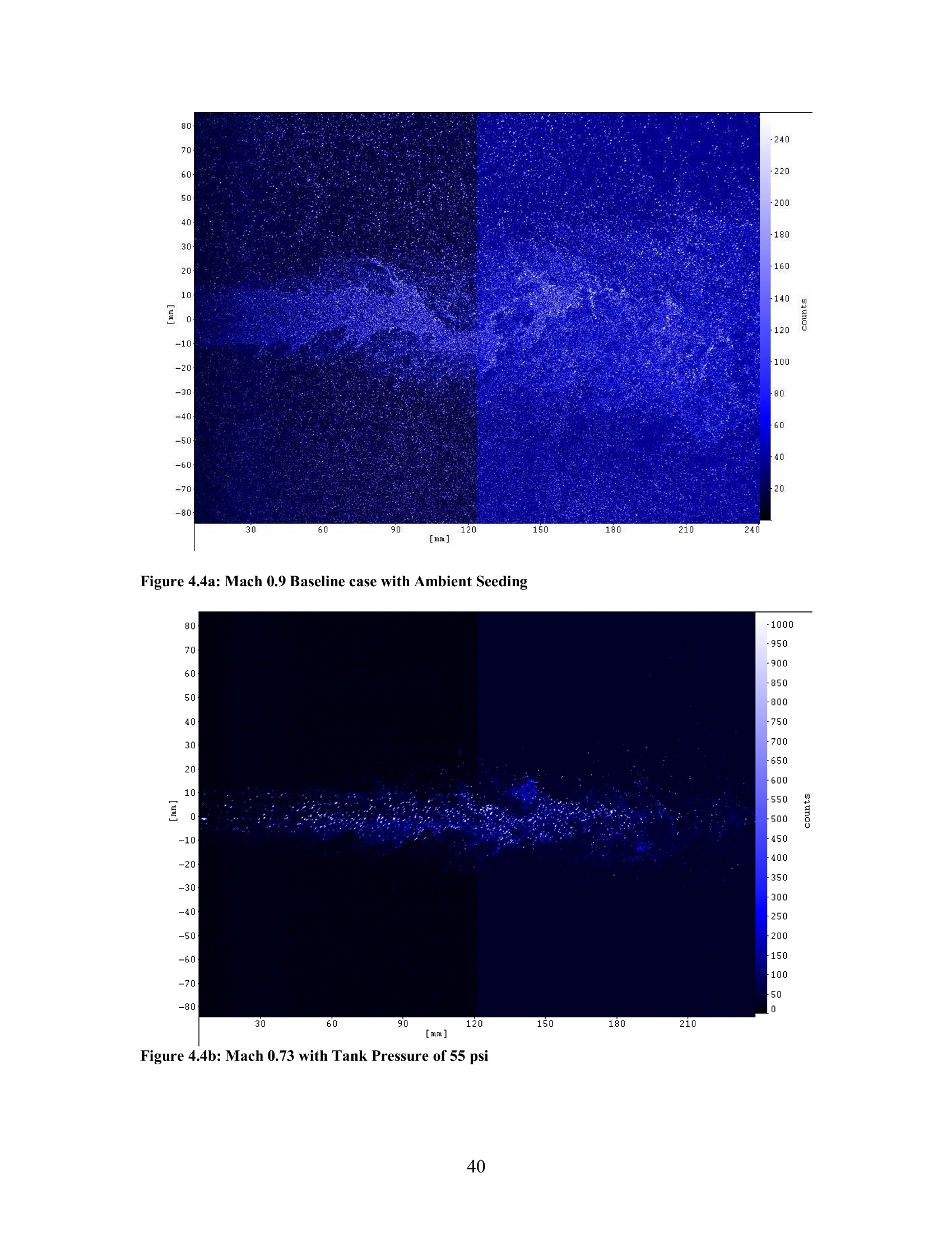
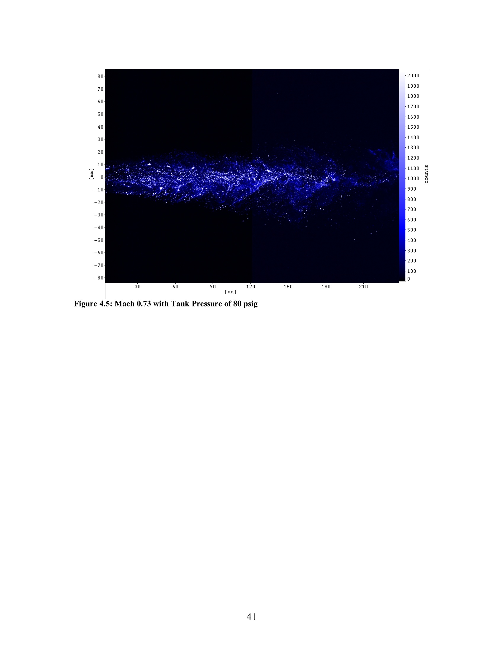
Chapter 3 Generating Uniform Sub-micron Solid Particles forLaser-based Flow Diagnostics A Thesis Presented in order to fulfill The Undergraduate Honors ProgramAt the Ohio State University By Keith Patrick Smelker ******* The Ohio State University 2006 Dr. Mohammed Samimy ABSTRACT New laser-based flow diagnostic techniques such as Particle Image Velocimetry are an attractive method for characterizing the velocity field of high-temperature jetflows. PIV required particle seeding and many current seeding techniques are not feasiblewithin a high temperature flow. This research focuses on developing a system to generateuniform sub-micron solid particles and to seed them into a jet system with a hightemperature air flow using a pH stabilized colloidal dispersion. The pH stabilizedtechnique was first developed at NASA’s John Glenn Research Center by Dr. MarkWernet. This research covers the design and development of a system to use the pHstabilized technique to produce sub micron particles for laser based flow diagnostics.Seeding is the key to producing accurate laser based diagnostics results. The seed sizeand material must be chosen to balance the ability to follow the flow, reflect measurableamounts of light, and exist within the testing application. For this research, 0.6 umaluminum oxide was chosen as a balance of these three characteristics. The system tointroduce these particles into the flow was produced based on its storage ability, flow andpressure control, and seeding capabilities. The system consists ofan 8 gallon stainlesssteel pressure vessel, a Tescom pressure regulator, stainless steel tubing, needle and ballvalves, and injector nozzles. The system produces seed for laser based flow diagnostics.Experiments were run at Jet Mach 0.9, 0.83, and 0.73 and compared to a baseline case atMach 0.9 to see how well the seeder seeded the flow. The results show that the seederproduces aluminum oxide seed particles, and each test showed steady improvement inseeding the flow homogenously. However, this first generation seeder never seeded theflow as well as the baseline case. Recommendations for running heated jet experiments, adding air atomizing nozzles, using a solenoid control valve, and running multipleinjection points are made to increase performance of the system. ACKNOWLEDGEMENTS I want to thank Dr. Samimy for mentoring and teaching me throughout thisproject. His constant mentoring and advising have helped me to learn a great deal aboutresearch and working in a research environment. I would also like to thank Dr. Samimyfor sponsoring this research.Without his sponsorship or support of this research, none ofit would have been possible. I would also like to thank Dr. Wernet at NASA for allowingme to use his notes and for answering any questions that I had throughout this wholeprocedure. Finally, I would like to thank Dr. Jin-Hwa Kim, Dr. Marco Debiasi, Dr. JacobGeorge, Jeff Kastner, Jesse Little, and Edgar Carabollo. Each of these people helped me agreat deal in the planning, designing, building, testing, and analyzing throughout thisproject. Without them, this thesis would not have been finished. Thank you all for all ofyour hard work and advise. TABLE OF CONTENTS ABSTRACT. ACKNOWLEDGEMENTS List of Figures. Introduction....... Background ..... 44 2.1 Introduction... 2.2 Particle Image Velocimetry...... 4 2.2 Basic Particle Principles...... 89 2.3pH stabilized Dispersion of Alumina in Ethanol ... 2.4 Particle Generation.. Design of Experimental Apparatus and Experimental Setup. 3.1 Major Seeder Design Parameters . 3.2 Seeder Design...... .3.3 Seed Type and Generation. 3.4 Equipment and Preparation ofa pH Stabilized Dispersion of Ethanol ... 3.5 Particle Image Velocimetry System.... 3.6 Experimental Methodology...... Discussion and Presentation of Results . 4.1Introduction... 4.2 Mach 0.9 Case . 4.3 Mach 0.83 Case.. 4.4 Mach 0.73 Case.... Conclusions and Recommendations for Future Work. 5.1 Conclusions .... 5.2 Recommendation for Future Work.. References...... List of Figures Figure 2.1: GDTL Free Jet System with PIV Setup 7 Figure 2.2: Mie Scattering Cross Section 7 Figure 2.3: Stable Dispersion of Aluminum in Ethanol 10 Figure 2.4: Cyclone Entrainment 13 Figure 3.1: Operational Schematic 21 Figure 3.2: Top of Seeder Tank 22 Figure 3.3: Seeder Tank and Control Panel 22 Figure 3.4: Hollow Cone Spray Pattern 23 Figure 3.5: No. 3 Fine Spray Nozzle 23 Figure 3.6: CAD Drawing of Cart 24 Figure 3.7: Cart with Seeder 24 Figure 3.8: Swagelok Compression Fitting 25 Figure 3.9: First Injection Point with Nozzle 27 Figure 3.10: Sonicator with pH stabilized dispersion of aluminum oxide 29 Figure 4.1a: Mach 0.9 Baseline case with Ambient Seeding 34 Figure 4.1b: Mach 0.9 Experimental Case Tank Pressure 50 psig 34 Figure 4.2a: Mach 0.9 Baseline case with Ambient Seeding 37 Figure 4.2b: Mach 0.83 with Tank Pressure of 47 psig 37 Figure 4.3: Mach 0.83 with Tank Pressure of 80 psig 38 Figure 4.4a: Mach 0.9 Baseline case with Ambient Seeding 40Figure 4.4b: Mach 0.73 with Tank Pressure of 55 psi 40 Figure 4.5: Mach 0.73 with Tank Pressure of 80 psig 41 CHAPTER1 Introduction Recently, the Gas Dynamics and Turbine Laboratory (GDTL) at the Ohio StateUniversity built a system to simulate free jet flows. The free jet nozzle is one inchdiameter and is located within an anechoic chamber that dampens the ambient noisewithin the system. A heater has also been added to the system to experimentally createheated flows that simulate jet exhaust. The goal of the research in this system is todevelop techniques to control the noise pollution radiated by different types of jet flows.Currently, Particle Image Velocimetry (PIV) is used to map the velocity of the turbulentflow structures. The study of these structures allows for new methods of noise reductionand noise control to be developed. Particle Image Velocimetry is a planar measurement technique used to map thevelocity field of a fluid flow (Melling 1998). Apulsed light sheet scatters light from theparticles. The particles are suspended in the flow, and two exposures are taken of theparticles. These images are compared in order to find the particle displacements between the two frames. This is done using a cross correlation technique where the images aresubdivided into regions and the regions are correlated using a digital Fourier Transformto find out which particle regions correlate most to one another the (Wernet 1994). Atwo-dimensional picture of the velocity field is then made using the cross correlationdata. In order to seed a flow correctly, a good seed particle must be chosen for thespecific application. An acceptable seed particle will be both large enough to scatter lightand small enough to follow the flow accurately (Wernet 2004). The seeded particles alsomust be distributed homogenously when introduced to the flow and not agglomeratedduring introduction to the flow. There are many different types of seeding materials andseeding techniques (Melling 1997). Currently, the GDTL utilizes a LaVision commercialoil particle generator to seed the centerline flow and a fog generator to seed the co-flow.For a heated flow the centerline seeder will not work because the oil particles willevaporate at the elevated jet temperatures. Research and design of a refractory metal seeding system for high temperature airflows has previously been done (Wernet and Wernet, 1995). A pH stabilized colloidaldispersion of alumina in ethanol is created using a technique such that the pH of thesolution is far away from the pHpoint of zero charge for the solution. The higher p inthe solution allows the particles sufficient energy to create a double layer of repulsionthat overcomes the Van der Waals bonds that normally inhibit the use of a refractory in aseeding solution. Tests showed that a pH 1 solution of alumina in 100% ethanol wouldstay stable for 2.5 days (Wernet and Wernet, 1994). A commercial paint sprayer with anatomizer can be used to create a high quality aerosol with this solution. In the previous research, a seeding system using a pH stabilized dispersion of alumina in ethanol wasdesigned and implemented for a high temperature compressor system and the tests weresuccessful (Wernet, et al. 1995). This paper describes the design and testing of a portable system to generate submicron particles for laser based flow diagnostics. The system concentrates on generatingsub micron Aluminum oxide particles suspended in pH stabilized Ethanol and injectedwith a commercial atomizer. Chapter 2 of this thesis details the theory behind generatinga well seeded flow. Chapter 3 details the design and testing procedure of the modularapparatus for generating the seed material and the apparatus used for the making the pHstabilized colloidal dispersion of Alumina. Chapter 4 shows and discusses the results ofusing the pH stabilized colloidal dispersion of Alumina versus using a commercialacetone seeder. Chapter 5 concludes on the work as well as makes recommendations forfurther work. CHAPTER 2 Background 2.1 Introduction Qualitative flow diagnostics within complex flow fields have been explored overthe last 100 years. With the technical progress within the last 20 years, qualitativediagnostics have evolved to the point where detailed quantitative measurement ofcomplex flow fields can be obtained (Raffel,et al.1998). Recently notable reviews ofplanar velocimetry (Samimy 1998) and particle seeding techniques (Melling 1997) havetaken place. New techniques for seeding high temperature air flows have also beendeveloped (Wernet and Wernet 1994) and tested (Wernet, et al. 1995). 2.2 Particle Image Velocimetry PIV is an indirect non-intrusive laser based flow measurement technique. Theentrained particle velocity is recorded by taking two successive images of the particlesilluminated by laser light. It is important to note that this is an indirect technique becausethe velocity of the particles is measured not the actual velocity of the flow. Laserillumination is generally carried out using a commercial laser and a series of mirrors andsplitters to shape the beam into a sheet of light. The sheet is directed over the flow ineither a cross-stream or stream-wise direction. Illumination of the particles happens according to Mie scattering theory which gives the cross sectional scattering property ofparticles. Mie scattering dictates that a particle that is much larger than the wavelength oflight will have a scattering cross section with varying intensity based upon theobservation angle, refractive index,particle size, and wavelength of light (Raffel, et al.1998). The cross sectional reflection of particles affects the seeding of the flow. As anexample, Figure 2.1 shows the Mie Scattering cross section for a particle. In this picturethe circles are logarithmic graphs of intensity based upon 100, and the x-y axis is thescattering angle from 0-360°. Looking at this picture shows that the intensity of lightvaries with the angle of observation. It also shows that light is reflected in a cross sectionand not in a point. This means that each particle seen in PIV images is actually smallerthan the visualized particles. Recording of the particle positions is accomplished with one of two techniques.The first technique utilizes two lasers and a single CCD (charged coupled device)camera. The laser sheets are placed as close together as possible. The lasers are firedwithin microseconds ofone another, and the camera takes two pictures of the flow basedon each laser pulse. The GDTL currently uses this technique. Figure 2.2 shows aschematic of the GDTL jet system and the PIV setup. The second technique uses twocameras and a single laser. The two cameras are each calibrated to pick up only one typeof polarized light, s or p light (Wernet 1995). When the laser illuminates the particle, thetwo types of polarized light are given off and recorded. In order to obtain the planar velocity map, thetwo images from either techniqueare collected and analyzed via a computer. The analysis is performed using a cross correlation technique that divides the image into sub-regions. Each of these interrogationwindows is subjected to a cyclic FFT given by the following equation: where I and Iz are the image intensities of the 1t and 2"d interrogation windows, and theC vector is the correlation strength of the displacement between the two interrogationwindows. The size ofthe interrogation window is given by n in pixels. More informationon this process can be found in the DaVis 7.0 Instruction manual. With these correlations,a vector map can be drawn and the flow velocity can be studied. Figure 2.1: Mie Scattering Cross Section (Wernet 2004) Figure 2.2: GDTL Free Jet System with PIV Setup 2.2 Basic Particle Principles When using laser based flow diagnostics, generating good seeding is key toproducing accurate results (Wernet 2004). In most seeding applications, the seedmaterial must be non-toxic, easily attainable, and can be readily introduced to the flow.The particles’ size must be chosen according to a couple of principles. Firstly since laserbased flow diagnostics do not measure the velocity of the flow directly but instead thevelocity of the particles within the flow, the particle must be small enough follow theflow accurately. The time constant of a particle to achieve constant speed within a flow isgiven by the following equation: where dp is the diameter of the particles, ts is the time constant, pp is the particle densityand p is the dynamic viscosity of the seeded medium or flow (Raffel, et al. 1998). Thisequation assumesthat the fluid acceleration isCconstant. Most flowscannot becharacterized using this simplification, but this is still a convenient measure of particlesettling time. Looking at this equation, the diameter of the particle lends a large amountof the time lag for the particle. With this, the smallest particles possible will follow theflow most accurately. In general, a particle of 1 um or smaller will acceptably followmost turbulent flows or high speed gas flows (Melling 1997). Even though the smallest particles will most accurately follow the flow, theparticles must also be large enough to scatter sufficient light for the camera. In general,the amount of light scattered by a particle is governed by the particle’s size, shape,refractive index., and the orientation of the particle (Raffel, et al.,,Willert, andKompenhans 1998). Thus, a balance exists between the particles being small enough to follow the flow accurately, and large enough to scatter light to be measured. The lightscattering characteristics of particles is very important in choosing an acceptable particle.For particles of similar size, the one with the higher refractive index will be the mostsuitable for a given application. The flow application also dictates the material of the particle used. There aremany different materials that can be used to properly seed a jet flow. Oil droplets or sometype of Polystyrene Latex Spheres (PSL) are commonly used. However, for hightemperature flows neither of these seed materials will work. PSL has a melting point of250℃ causing agglomeration at elevated temperatures (Wernet 1995). Oil dropletsevaporate in flows where the temperature reaches levels far above ambient. Refractorymetals are used for flows in which the temperature is above ambient (Melling 1997).Since the GDTL has started to use high temperature flows, this paper will focus on beingable to generate sub-micron aluminum oxide particles for flow measurements. Aluminumoxide is a non-toxic, high refractivity, and easily attainable particle that is available insubmicron sizes. Normally, aluminum oxide particles agglomerate when introduced to aflow. However, a new mixing technique has been made where the pH of the aluminumoxide solution is stabilized to stop agglomeration (Wernet 1994). 2.3 pH Stabilized Dispersion of Alumina in Ethanol Since aluminum oxide has a tendency to agglomerate when introduced to a flow,a new technique was developed in order to make aluminum oxide a viable seedingoption. When a solid particle is suspended in a solution, the inter-particle forces dictatehow stable the suspension will be. A suspension is stable once the repulsive forces arestronger than the attractive forces. When a particle is introduced into an acidic or basic solution, the polarity of the solution causes repulsive or attractive electrostatic forcesdepending upon the sign and strength of the polar solution. In a solution, the point of zerocharge is the point where the polarity of the solution does not create an electrostatic layeron the particle. When the pH is below this point, a repulsive electrostatic layer isdeveloped on the surface of the particles. To create a stable dispersion of alumina inethanol, the pH of the solution must be lowered far below the point of zero charge foraluminum. Figure 2.3 illustrates how lowering the pH will create a stable dispersion(Wernet 1994). With a stable dispersion of aluminum in ethanol, the dispersion can beintroduced to the flow without major agglomeration. 2.4 Particle Generation Particle generation for seeding a flow is done on either a global or a local level.Local seeding is the process by which seed is introduced into only the section of the flowfield that is of interest for study. To accomplish local seeding, the seed is normallyintroduced into the flow at the area of study. Global seeding introduces seed to the entireflow field. Two parameters are important in global seeding. First of all, the injectionpoint must be far enough upstream that the particles will be evenly distributed throughoutthe flow when the area of study is reached. Secondly, the injection point must notseverely interfere with the flow. For this study, global seeding will be used. The density of particles entrained within a flow is critical to generating PIVimages that accurately approximate the movement of a complex gas flow. Firstly, there isa limit to the density of particles the flow. This limit is based upon the scatteringcharacteristics of particles. Each particle has its own scattering cross section that thecamera records. As the particles become closer together the intensity cross sections beginto overlap. This introduces noise into the image such that affects the accuracy of the PIVrecording (Samimy 1998). There is also a lower limit to the number of particles within aregion of flow. The flow field dictates that there enough particles to characterize the flow.The general rule is that there should be at least 6-10 particles per interrogation window(Wernet 2004). Secondly, uniform particle number density is also important in accuratelycharacterizing a complex flow field. A homogenous particle distribution gives the samenumber of particles in each interrogation window. A perfectly homogenously seeded flow will not show any flow structures but will have the same density of particles throughoutthe flow. This ensures that each section of the flow is characterized accurately. There are multiple ways to introduce particles into a flow including oil particlegenerators, fog generators, cyclone entrainment, fluidized beds, and atomizers (Wernet2004). Oil particle and fog generators use a condensation technique to create sub-micronoil particles. These particles are then injected into the flow. The GDTL employs both acommercial atomizer from LaVision to seed the core jet flow, and a theatrical foggenerator for ambient air seeding. Cyclone entrainment and fluidized beds use a highpressure air jet to create a cyclone that picks up the small particles on the bottom of thetank and introduces them to the flow through the top of the tank. These techniques arenormally used for introducing dry solid particles to a flow. Figure 2.4 illustrates thecyclone entrainment technique. Atomization is also a technique to introduce a solidparticle to a flow. Atomization requires solid particles to be suspended within a liquid,and the liquid is pushed through a nozzle to create a quality aerosol. A liquid with a lowvapor pressure, and an injection point well upstream of the area of study is used to makesure that the liquid is completely evaporated before the area of study. Figure 2.4: Cyclone Entrainment (Wernet 2004) Design of Experimental Apparatus and Experimental Setup 3.1 Major Seeder Design Parameters While the goal of the seeder is to produce uniform solid particles throughout theflow, the design of the components was based on a few crucial parts: storage ability,adaptability, pressure and flow control, and portability. Storage ability is broken downinto two components, corrosion resistance for handling acidic dispersions and capacity tohold an hours worth of seeding solution. Adaptability is based on the seeder’s ability tobe used for multiple facilities in multiple arrangements. This means using parts andpieces that can easily be removed and reattached without a significant overhaul on thesystem. Pressure and flow control allow for multiple injection pressures and mass flowrates be used with Mach numbers ranging from 0-2. Portability is important for movingthe seed generator to and from multiple facilities without a large amount of work. 3.2 Seeder Design After reviewing the design of the seeder used from previous research and keepingin mind the design parameters, a system schematic was designed to highlight the majorparts of the design. Figure 3.1 shows the schematic for the system.This schematic outlines the major components to introduce the pH stabilized dispersion into the free-jetfacility. Shop air is supplied to the tank to create a differential pressure between the tankand the jet facility. The liquid will then flow from the tank and be injected into the jetfacility. The tank is the central and largest part of the system. It is made of Schedule 8010”316 Stainless Steel pipe and the flanges are 300# 316 Stainless steel flanges.Stainless steel was used because of its strength, durability, and corrosion resistance.Flexitallic spiral wound gaskets were used to seal the tank. This type of gasket reducesthe effect of cathodic and anodic corrosion due to dissimilar metals coming into contact.The height of the tank is 40”and is capable of holding 8 gallons of pH stabilizeddispersion. Two 2” holes were drilled in both the top and the bottom of the tank to drainand put in the liquid. Both of these holes are tapped and plugged during operation. Thebottom of the tank was machined to make a sloping drain throughout most of the bottom.Three 3/8”holes are also drilled and tapped into the top of the tank; one is the inlet forthe pressurized air, one is the outlet, and one is the pressure release. Two tubes reach intothe tank cavity.The first tube reaches into the mid-section of the tank and is the inlet forthe air. The second tube reaches to 4”from the bottom of the tank and is the outlet forthe liquid. All of the tubes within the tank are 3/8”stainless steel connected withSwagelok fittings. Pressure is released from the tank with a 3/8”Stainless steel ball valve.Figure 3.2 shows the top of the tank. A pressure regulator controls the pressure of the air coming into the tank. Thevalve is a Tescom 44-1300s rated for 500 psi inlet and 0-150 psig outlet. It has a brassbody and has a single port for a pressure gauge. Brass was chosen as the material due to price. The maximum inlet pressure from the shop air is 120 psi and the maximumpressure needed is 100 psi for a Mach 2 flow. Both the inlet and outlet pressure for theregulator meet these specifications. Figure 3.3 shows how the Tescom Regulator issituated with the controls to the seeding system. The Tescom regulator is on the left ofthe picture with the inlet stream of air, and the flow rate controls are on the right with theoutlet streams of pH stabilized dispersion. The outlet from the seeder is split into two streams and sent to the injectors. Twooutlets were designed in order to accommodate multiple injection layouts. An adaptableinjector layout allows the seeder to be used not only for the jet facility but also to seedother facilities. It also gives flexibility in seeding the flow such that a co-flow seed can beproduced, as shown in Figure 3.1, or for seeding the core jet from multiple points. A co-flow injection means that the ambient air around the jet is seeded such that the entrainedair is seeded as it is entrained within the jet. Both of the outlets from the seeder are madeof 3/8” 304 Stainless Steel tubing. Tubing connections are all stainless steel Swagelokcompression fittings. Stainless steel was used for its corrosion resistance and Swagelokwas used for its ease in attachment and removal. The fittings and tubing can be seen inFigure 3.4. Control for the seeder outputs is accomplished through a couple of differentmechanisms. As shown in Figure 3.4, the primary flow control is accomplished through aball valve followed in series by a needle valve. A pressure gauge in between the valvegives the liquid output pressure and can be used to approximate the injection pressure.The ball valve gives the system two features. Firstly, turning the flow on and off fromthis point is accomplished without having to reduce the pressure within the tank. Thus, the system can be modified while it is still online. Sections locked down by ball valvescan be taken off and replaced without having to drain the tank. Secondly, this valve actsas a quick disconnect point where the valve can be closed and all of the tubing after thevalve can be adapted without having to vent the tank or turn off the incoming air. Theneedle valve gives the mass flow control for the system. Using a smal needle valve, asshown in Figure 3.4, allows for good resolution in control of the flow to the injector.However, a pressure loss is introduced to the system when the valve is barely open suchthat the gauges located at the control panel will not precisely give the injection pressure.Both of these valves are rated for 3000 psi and are made of 304 stainless steel. The gaugereads 0-300 psi and is rated for either liquid or gas. Commercial Atomizers accomplish injection to the jet flow. Atomization is usedfor seed generation because in order to generate a quality refractory metal aerosol the pHstabilization technique had to be used. Since this technique introduces the seed to aliquid, atomization fit the best for this process. A Spray Systems 1/4LND-316SS typefine spray nozzle was selected. This is a 303 stainless steel wall mounted nozzle thatproduces a spray by pushing a liquid through a small orifice. It produces the hollow conepattern as seen in Figure 3.5. A hollow cone pattern allows the seed to be distributed in awide angle throughout the flow such that mixing will occur rapidly within the flow. Inselecting this nozzle, four orifice sizes were selected to give control over the amount ofseed introduced to the flow at a given pressure. Table 3.1 shows the orifice sizes andmaximum flow for each of the nozzles. These four nozzles give a wide amount offlexibility in choosing the right flow rate to produce a uniformly seeded flow. The flowrates listed in the table are for a pressure of 300psi. Since the shop air is at 120 psi, this high of flow rate will never be seen and does not factor into the decision to use these fournozzles. Figure 3.5 shows one of the nozzles used. The nozzle has a threaded head suchthat it can be wall mounted directly into the injection point on the jet facility. OrificeNumber Orifice Size(in.) Maximum Flow rate at 300 psi(gph) 3 0.028 8.2 6 0.042 16.5 10 0.064 27 14 0.076 38 Table 3.1: Nozzle Orifice Sizes and Maximum Flow rates (Spray Systems Co. 2004) The final major part to designing this system was making the system bothportable and adaptable to other facilitiess easily. Since the tank weighs in excess of 600lbs while empty, making it portable presented a sizable challenge. Previously, an acetoneseeding system was designed to be moved using a dolly. However, when considering theweight of this system compared to that of the acetone system, this proved to be unfeasibleand hazardous. The second option was to order a prefabricated cart that the tank could bebolted to and moved using the cart. A stainless steel heavy duty cart was ordered toaccomplish this task. This seemed like a simple solution to moving the tank without alarge amount of design work being done. The wheelbase for this cart was in a diamondpattern that was unstable when put under high point loads given by the support studs forthe tank. Finally, a small cart with a rigid structure was designed using Solid Edge. Figure3.6 shows the CAD picture of the cart. This design gives both horizontal and verticalsupport for the tank while it is on the cart. The horizontal supports between the mainsupports give rigidity to the cart structure, and the transverse supports give lateral supportto the structure as the cart moves. The base cart is a 24”x 36”commercially available cart rated for 1200 lbs equipped with 9" diameter wheels. Having large wheels ensuresthat bumps and discontinuities on the floor will not compromise the stability of themoving tank. The structure on the cart stands 44” high and is 24”square. This footprint is6.5”greater than that of the tank such that the horizontal support can be taken off of thestructure and the tank can be moved from the cart. During construction of the cart, thelong transversal pieces were switched for shorter floor mounted brackets. These wereeasier to make and smaller while giving adequate stability for the cart. Figure 3.7 showsthe completed cart with the seeder on it. The structure for the cart is made ofU-Shapedbar with " bolts slots located at every inch of the bar. The main supports are welded tothe cart. The side horizontal supports are bolted to main supports with ” bolts.Overall,this gives a stable and easily portable design for the seeder. Adaptability for the system was accomplished in a couple of ways. Firstly, all ofthe tubing and pipe fittings are done using Swagelok compression fittings. These fittingsdo not use Teflon but are self sealing based upon compression of a metal ring that isforced onto the tubing. The configuration of the components can be changed easily withan adjustable wrench. Figure 3.8 shows the compression ring inside of the Swagelokfitting. Secondly, all of the tubing and pipe fittings for the system were based upon 3/8”stainless steel tube. With a single tube size throughout the system, all pieces can bemoved around within the system to find a suitable controls configuration for eachapplication. Finally, ball valves were used extensively within the design to increase themodularity of the design. With these ball valves in place, each section of the tubing is itsown module that can be shut off from the rest of the system for changes or repair without having to drain the tank or stop the pressure. In these ways, the system is adaptable tomultiple configurations. Looking at the overall design of the seeder system, it meets the major designparameters in the following ways. As far as storage capabilities, the tank has storagecapabilities for 8 gallons of pH stabilized dispersion which is more than enough forcontinuous operation for 2 hours, and all parts coming in contact with the acidicsuspension are stainless steel with good corrosion characteristics. The tank also has amaximum pressure rating of 300 psi which is significantly higher than the 120 psi givenfrom the shop air. It is adaptable to multiple configurations using Swagelok componentsand modularity achieved through ball valves. Pressure and flow control are achievedthrough the main Tescom Regulator, needle valves, and multiple types of injectornozzles. The cart makes the system portable to all points in the laboratory. Overall, thedesign meets all of the major design parameters for making a seed generating system. From Shop Air Figure 3.1: Operational Schematic Figure 3.2: Top of Seeder Tank Figure 3.3: Seeder Tank and Control Panel Figure 3.4: Hollow Cone Spray Pattern (Spray Systems 2004) Figure 3.5: No.3 Fine Spray Nozzle Figure 3.6: CAD Drawing of Cart Figure 3.7: Cart with Seeder Figure 3.8: Swagelok Compression Fitting 3.3 Seed Type and Generation From the beginning of this project, aluminum oxide was the material of choice,but significant effort went into choosing a particle size and delivery system to the jetcore. In previous experiments, the seed used was Sumitomo AKP-15 particles with amean particle size of 0.7±0.2 um (Wernet 1995). However, at the time of this researchthese particles were not available, so a particle size had to be chosen based upon thesystems present at the GDTL and current particle sizes offered by manufacturers. Asexplained previously, the particle size is a balance between being small enough to followflow accurately and also large enough to refract a measurable amount of light. With thisin mind samples of two particles were obtained for experiments. Sumitomo contributed 2kg each of AA-3 and AA-5 high purity aluminum oxide. The AA-3 and AA-5 particleshave a mean diameter of 0.3 um and 0.6 um, respectively, and are of 99.99% pure. Sincethe previous research used a 0.7 um particles with great success the 0.6 um particles werechosen as the primary seed keeping the 0.3 um particles as an experimental. This sizeparticle has a lag time constant of 4.4 us which does not affect its ability to accuratelyfollow the flow, and with a refractive index of 3.96 this particle will reflect enough lightto be measurable by the PIV system. Generation of the seeding particles is done through acommercial atomizer as explained above. Two injection points are available on the jetsystem. One is located at 9 ft upstream of the area of study and the second is locatedabout 12 feet from the area of study. Figure 3.9 shows the first injection point. Thispicture shows that the nozzle injects the liquid directly into the flow. The secondinjection point has a bend before the area of study which is thought to help in the mixingof the particles within the flow. Figure 3.9: First Injection Point with Nozzle 3.4 Equipment and Preparation ofa pH Stabilized Dispersion of Ethanol For complete instructions on how to prepare a pH stabilized dispersion ofAlumina in ethanol can be found in the literature (Wernet 1994). A 1% wt Aluminumoxide suspension was prepared using the Mass Balance Equation: where M is the mass of aluminum oxide in grams, p is the density ofethanol, and V is thevolume of ethanol in milliliters. Using this equation 34 grams of aluminum oxide wereadded per gallon ofethanol. The dispersion was prepared in segments of 200 ml where an8.5% wt alumina dispersion was made and diluted to 1% with 800 ml of stabilizedethanol solution. For a 200 ml dispersion of aluminum, the sonicator was used for 6-8minutes with a 50% power level and a duty cycle of 1 second on and one second off.Figure 3.10 shows a picture of the Sonicator transducer and the 8.5% wt. aluminum oxidedispersion. Using this procedure, the pH stabilized dispersion of alumina in ethanol wasprepared and used. Figure 3.10: Sonicator with pH stabilized dispersion of aluminum oxide in ethanol 3.5 Particle Image Velocimetry System The Particle Image Velocimetry acquisition and processing system is a LaVisionPIV System. This system encompasses all of the acquisition and processing equipmentand controls. Images are acquired using a Red Lake 2000x2000 pixel CCD camera with a90 mm Tamron lens. Control of the system is accomplished using a programmable timingunit (PTU). A dedicated PC with Xeon Intel Processor houses all of the DaVis 7.0software and essential hardware. The PTU controls the operation of a Dual Head SpectraPhysic;ss 400 mJ Nd:Yag Laser. FoFro rt htihsi sa pappplilicacattiioonn., the laser was used in the secondharmonic (532 nm) and at 70% of its rated power. Image sets were acquired at a rate of1Hz and the laser pulses were programmed for a 2 us space between each image. Thelaser sheet was produced using a set of cylindrical and spherical lenses. Great cataken in aligning each of the lasers and a dot card was used to calibrate the system andfocus the camera. 3.6 Experimental Methodology Testing for this system was based on a couple of different goals. First of all, thesystem needs to show that it can generate sub-micron Aluminum oxide particles.Secondly, the new seeder should show that it is comparable in ability to the current setupat the GDTL. In order to accomplish these goals a series of tests were run. The GDTL,currently, uses an atomizer as its normal core flow seeder, and a fog generator forambient air. Mach 0.9 is the case for which this seed generating produces a well seededflow. To compare the aluminum oxide seeder with this case, an experiment at Mach 0.9was done as well as two experiments at Mach 0.73 and 0.83. For the Mach 0.9 case, threeinjector nozzles were tested numbers 14, 6, and 3. For the Mach numbers lower than 0.9, the second injection point was used to see whether it improved uniformity in the seed.Throughout each of these cases, the pressure within the tank was varied. At each of thedifferent Mach numbers and tank pressures, multiple PIV images were taken andprocessed to compare with the baseline case. They were also studied to look at ways ofimproving the new seeding technique. It is important to note that when implementing anew seeding technique, an iterative scheme is needed to correctly seed a flow. Testingusing multiple Mach numbers, injection points, and tank pressures should show how eachof these variables improves the seeding technique. Chapter 4 Discussion and Presentation of Results 4.1 Introduction Using the aforementioned apparatus, as discussed in Chapter 3, and instructions toprepare pH stabilized solutions of aluminum oxide in ethanol, experiments were runaccording to Case 1, Case 2, and Case 3 by Mach number. Images were taken at eachMach number and analysis was done by studying the images and qualitatively comparingit to a well seeded baseline case of seeded with oil particles. Comparisons are based uponthe uniformity of the seed within the flow, a homogenous density, and also as the casesprogressed on how improvements changed the results. It is important to note that thebaseline images have the ambient air seeded and the test cases do not, so all of theanalysis and discussion focuses on the jet core. 4.2 Mach 0.9 Case Figure 4.1a shows the Mach 0.9 baseline case and Figure 4.1b shows an exampleof an image taken with the Aluminum oxide seeder at Mach 0.9. In each of thesepictures, the color bar is a measure of intensity reflected from particles and the scales inmillimeters are the coordinates within the actual flow. This experiment was run with the tank pressure at 55 psig, with an injector nozzle number of 3, and with injection at thefirst inlet. Tests were run using both the number 6 and number 14 fine spray nozzles, butthe flow rate produced an extremely dense seed that did not characterize the flow well.Looking at the baseline case, the seed is uniformly distributed throughout the flow. Thisis seen by the uniform intensity particles throughout the picture. The density is also veryuniform and within the established bounds because single particles can be seen. Lookingat the picture for the test case, the seed is not uniform and it has too high of density. Theuniformity and density are both seen in the middle of the flow where the seed appears asa single white streak. This streak is either a very dense section of seed or liquid ethanolspread within the flow. Throughout this experimental case, ethanol was dripping out ofthe jet nozzle due to the extensive amount of seed being introduced into the jet.Comparing the baseline core flow with that of the experimental case, the experimentalcase does not show the entire jet, but instead the seed is concentrated towards the top ofthe jet. For this case, the seeder is producing a seed however it is not uniform and toodense to acquire accurate PIV data. Figure 4.1a: Mach 0.9 Baseline case with Ambient Seeding 0 Figure 4.1b: Mach 0.9 Experimental Case Tank Pressure 50 psig 4.3 Mach 0.83 Case Figure 4.2a shows the Mach 0.9 baseline case and Figure 4.2b shows anExperimental image at Mach 0.83 and a tank pressure of 47 psig. In analyzing thesepictures, it is important to note the changes that were made between this case and theMach 0.9 case. In this case, the injection point was placed at 11 ft upstream from the flowand it is separated by a bend to enhance the mixing characteristics of the flow. Also,multiple data sets where taken corresponding to different tank pressures to see howchanging the injection pressure changes the way seed is distributed throughout the flow.Looking at the case with a tank pressure of 47 psig shows extensive improvement overthat of the Mach 0.9 case. The bright spots surrounded by sections of dark show that thedensity and distribution of the seed is still not completely comparable to that of thebaseline case. In this case, the seed was mixed better than in the Mach 0.9 case, and theamount of seed injected was closer to the baseline case. The 47 psig case still does notcompletely characterize the flow. Figure 4.3 shows an image of the Mach 0.83 case experimentally seeded with thealuminum oxide seeder at a tank pressure of 80 psig. This picture shows a greatresemblance to that of the 47 psig case. This case again shows a fairly good cloud of seedthroughout the picture, but it also shows places where bright spots exist without anycloud around them. Each of these bright spots is a place where the seed density is toohigh and the camera cannot pick up individual particles. The higher tank pressure showsless bright spots. This means that the increase in injection pressure helped to make theparticles mix more evenly with the flow. This case showed some progress towards thebaseline case. Looking at the Mach 0.83 case as a whole, a couple of important things werelearned during this experiment. First of all, the second injection point helps with mixingthe particles throughout the flow a great deal. In comparing this case with that oftheMach 0.9 case, the seeding was better distributed and the density was at a place wherePIV measurements could be made. However, there are still discontinuities in thedistribution and density ofthe particles. It was also noted in this case that the needlevalve did not give good control resolution. The valve only needs to be opened a verysmall amount for there to be enough seed, so control resolution is a problem incontrolling the amount of seed entering the flow. It was seen that this case was a greatimprovement over that of the Mach 0.9 case. Figure 4.2a: Mach 0.9 Baseline case with Ambient Seeding Figure 4.2b: Mach 0.83 with Tank Pressure of 47 psig 的00 Figure 4.3: Mach 0.83 with Tank Pressure of 80 psig 4.4 Mach 0.73 Case Figures 4.4 and 4.5 show the comparison of the baseline case with that of theexperimental case at a Mach number of 0.73 and tank pressures of 50 psig and 80 psig.Within in this experiment, the second injection point was used. Looking at the 50 psig setof images, the experimental case shows a fairly homogenous distribution throughout theflow. This is seen in the cloud that characterizes most of the jet. Some parts of this doshow places of bright spots and dark spots. This shows that the seed is still notcompletely mixing with the flow. However improvement has been made between thiscase and the Mach .83 cases. The 80 psig case shows too much seed within the flow. Inthis picture there are bright spots littered throughout the seeded region. These spots areplaces where the particle density is such that the scattering cross sections are overlappingand discrete particles cannot be seen. The 80 psig case also shows a non homogenousdistribution of particles within the flow. The particles seem to be seeded towards thebottom of the jet and not as many in the top part of the flow. Comparing the twoexperimental cases shows that increasing the injection pressure does increase the amountof seed within in the flow. It does not, however, increase the seeds ability to mixthroughout the flow. It is also interesting to note that throughout this experiment, ethanolwould begin to drip out of the jet nozzle when the seed generator was generating toomuch seed. This is interesting because is shows that the ethanol is not completelyevaporating, and it also says that some of the particles viewed within the pictures couldbe ethanol droplets and not alumina particles. Figure 4.4a: Mach 0.9 Baseline case with Ambient Seeding 0 Figure 4.4b: Mach 0.73 with Tank Pressure of 55 psi Figure 4.5: Mach 0.73 with Tank Pressure of 80 psig Conclusions and Recommendations for Future Work 5.1 Conclusions After analyzing all of the data and studying the results, the following conclusionscan be made. First of all, the new seeder does produce sub-micron particles for laserbased flow diagnostics. All of the cases show that seed is being generated however, theseeder does not produce a uniform seed and it is not easily controlled. Non-uniformity isseen in all of the experimental figures where bright spots exist at many places and aconsistent particle cloud does not exist as it does in the baseline case. Controllerresolution is seen in all three of the experimental cases where changing the needle valveposition a very small amount had a drastic effect on the amount of seed introduced to theflow. Secondly, these experiments demonstrate the ability to produce a pH stabilizeddispersion of Aluminum oxide in ethanol. Being able to produce the seeding materialeasily had great affects on making the experiments possible and on how the experimentsran. Thirdly, the seed generator showed its portability, adaptability, and ease ofusethroughout the experiments. The portability was demonstrated with the cart, adaptabilitywas demonstrated during experiments by changing injector nozzles without draining the tank, and ease ofuse is demonstrated by the Mach 0.9 being the first test ever run withthis seeder and it working. While the seeder did generate seed, it did not generate a uniform particle densitynumber or homogenous distribution of seed throughout the flow. This was seen in all ofthe experimental cases. The Mach 0.9 case had the worst distribution and seed density,and as the experiments progressed the seed densities and distributions improved.Thepictures still did show that the improvements were not complete and that even in theMach 0.73 case, the seed exhibited many places with a high density and low density. Partof the problem with the density and distribution was the lack of control resolution withthe system. The needle valve did give as much resolution in controlling the mass flowrate of seed as was originally expected. This resulted in having very little control overhow much seed was introduced to a system. Ethanol condensation happened when theseed mass flow rate was too high. This shows that evaporation was not occurring at ahigh of rate as was needed to produce completely dry seed. This contributed to the highdensity sections of seed within the images due to theagglomerations of liquid withparticles suspended in it. While the generator did not generate a perfectly seeded flow,the experiments showed that the pH stabilized dispersion was a viable seeding solutionand the seeder worked for introducing the seed solution into the flow. 5.2 Recommendation for Future Work After looking at the conclusions, a few of design and experiment parameterimprovements present themselves. First of all, experiments using the heated jet should berun. This will better characterize the abilities of this system since its design was for aheated application. Also, heating the jet will alleviate the problem of having ethanol droplets within the flow. Secondly, the first addition to the system should be an airatomizing nozzle. The currently used nozzle is a liquid atomizing nozzle which onlypushes a pressurized liquid through a small orifice. An air atomizing nozzle uses a secondstream of air within the nozzle to mix with the liquid before it goes through the orifice.The main reason for using this type of nozzle is to enhance the mixing abilities of theparticles. By introducing air into the nozzle, the density of the injection stream is less, sothe air and dispersion mixture should mix with the flow more easily. This is also the sameinjection system that Dr. Wernet used in the previous research (Wernet and Wernet1994). This type of system will create a finer spray such that the system should create amore uniformly seeded flow field. By using these recommendations, completely new setsof results can be attained to see how well the seeder works within a heated jet and incomparison to the previous research. Adding a solenoid control valve presents a way to increase the control resolutionof the system. Controlling the system with good reliability was a problem that presenteditself throughout each of the cases.The needle valve that was used could only be openeda very small amount to seed the flow with the right amount of seed. Opening the valveonly a small amount introduces a pressure loss into the system. The control of thepressure is linked to that of the mass flow rate. Using a solenoid control valve wouldallow separate control of both of these variables.A solenoid control valve works byopening and closing a valve at a specified rate to produce a given mass flow rate withoutaffecting the pressure. The con to adding this is that it needs an electrical input with acontrol system. It will, however, add much needed control to the system. Control shouldallow the experiments to be The final recommendation to improve the ability of the system to create auniformly distributed flow is to use multiple injection points. Currently, the seed is notwell distributed throughout the flow. Instead,the seed tends to be grouped within onesection of the flow and not in other sections. The main cause ofthis is that the injectionpoint is too close to the area of study. The heater does not allow the injection point to bemoved any further upstream. In order to increase the homogeneity of the seed, moreinjection points should be added. With multiple injectors, mixing does not have to happenthroughout the entire flow but in each section of the injector. As a trial, a second injectionpoint could be added to have symmetry in the injection of the seed. Currently, the resultsshowed that the seed tended to be concentrated on the top or the bottom of the flow fieldand a second injector would solve this problem. In all, running heated jet experiments,adding air atomizing nozzles, using a solenoid control valve, and increasing the numberof injection points are recommendations to improve future work done with this system. References Melling, A. “Tracer Particles and Seeding for Particle Image Velocimetry,”Measurement Science and Technology, Volume 8, 1997.1406-1416. Raffel, et al., M., Willert, C., and Kompenhans, J. “Particle Image Velocimetry: APractical Guide.”Springer-Verlag Berlin Heidelburg, New York, NY: 1998. LaVision GmbH,DaVis FlowMaster Software Manual for DaVis 7.0,Gottingen, Germany,2004. Samimy, M.“A Review ofPlanar Multiple-Component Velocimetry in HighSpeed Flows,”20* AIAA Advanced Measurement and GroundTesting Technology Conference, Albuquerque, NM, June 15-18, 1998. Spray Systems, Inc. “Technical Specifications for Fine SprayNozzles.””www.spraysystems.com, 2004. Wernet, M., Wernet, J. and Skoch, G.“Demonstration ofa Stabilized Alumina/Ethanol Colloidal Dispersion Technique for Seeding High TemperatureAir Flows,”16" International Congress on Instrumentation forAerospace Simulation Facilities, Wright-Patterson Air Force Base, 1995. Wernet,M. “Fundamentals of Digital Particle Imaging Velocimetry,”Course Notes, 2004. Wernet,M., “Fuzzy Inference Enhanced Information Recovery from Digital PIVusing Cross Correlation Combined with Particle Tracking,” SPIE Conferenceon Optical Diagnostics in Fluid and Thermal Flow, San Diego, CA,July 9-14, 1995. Wernet, M. and Wernet,J.,“Stabilized Alumina/Ethanol Colloidal Dispersionfor Seeding High Temperature Air Flows,” ASME Symposium onLaser Anemometry, Lake Tahoe, NV, June 19-23,1994. Wernet,M.“pH Stabilized Alumina Dispersions Instructions,”Notes, July 8, 1994. ii iii
确定


还剩51页未读,是否继续阅读?

产品配置单

北京欧兰科技发展有限公司为您提供《流体中速度场检测方案(粒子图像测速)》,该方案主要用于其他中速度场检测,参考标准--,《流体中速度场检测方案(粒子图像测速)》用到的仪器有德国LaVision PIV/PLIF粒子成像测速场仪、Imager SX PIV相机
推荐专场


相关方案
更多
该厂商其他方案
更多