


方案详情
文
Abstract—In-cylinder flow field structure in an internal
combustion (I.C) engine has a major influence on the combustion,
emission and performance characteristics. Fluid enters the
combustion chamber of an I.C engine through the intake manifold
with high velocity. Then the kinetic energy of the fluid resulting in
turbulence causes rapid mixing of fuel and air, if the fuel is injected
directly into the cylinder. With optimal turbulence, better mixing of
fuel and air is possible which leads to effective combustion. A good
knowledge of the flow field inside the cylinder of an I.C
engine is very much essential for optimization of the design
of the combustion chamber for better performance especially
in modern I.C engines like gasoline direct injection (GDI),
homogeneous charge compression ignition (HCCI)
engines.The main objective of this work is to study the incylinder
fluid flow field characteristics of a single-cylinder
engine to see the effect of intake manifold inclination at
equivalent rated engine speed using Particle Image
Velocimetry (PIV) under various static intake valve lift
conditions. To facilitate the PIV experiments, the metal cylinder of
the engine was replaced by a transparent one. For every operating
test condition, 50 image pairs were captured and processed using
DAVIS software. From the results, it is seen that the in-cylinder
flow structure is greatly influenced by the intake manifold
inclinations irrespective of intake valve lift. Maximum Turbulent
Kinetic Energy (TKE) was highest at full intake valve lift
irrespective of the inclination. Also, the maximum TKE was
the highest for 600 intake manifold inclination compared to
other inclinations irrespective of the intake valve lift at
equivalent rated engine speed. Finally, it is concluding that
the analysis carried in this work is useful in predicting the
flow and inturn optimizing combustion chamber of modern
I.C engines.
方案详情

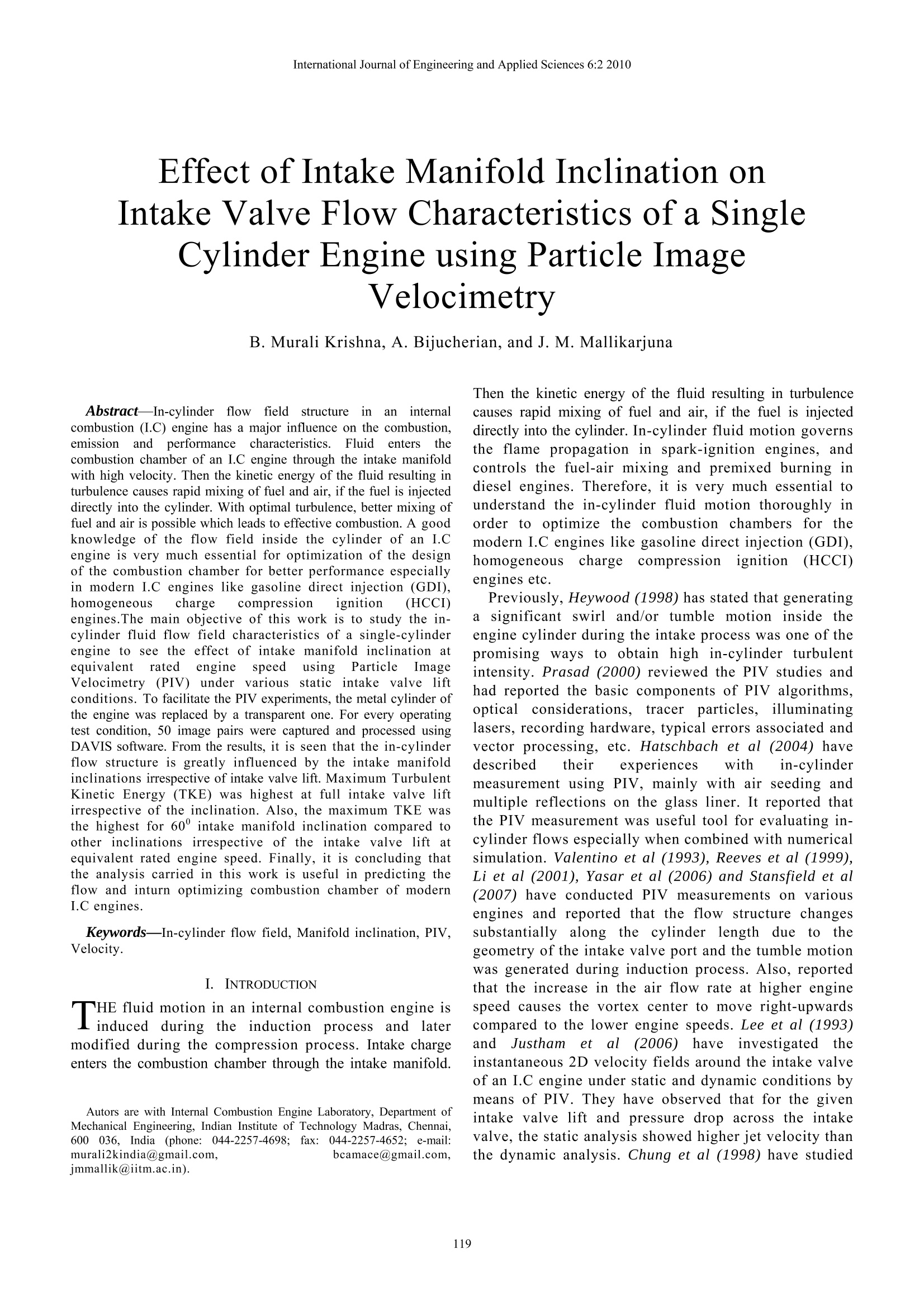
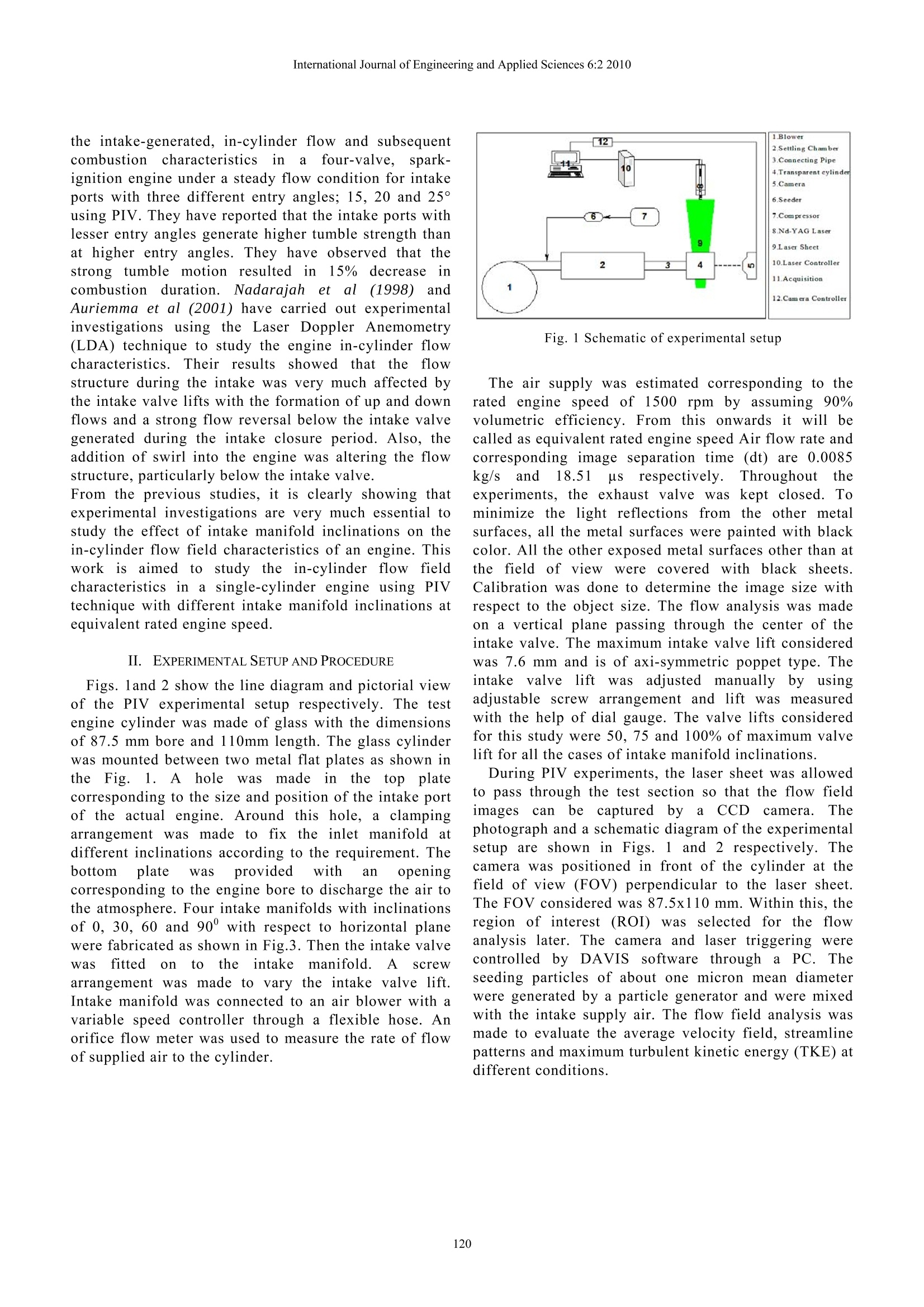
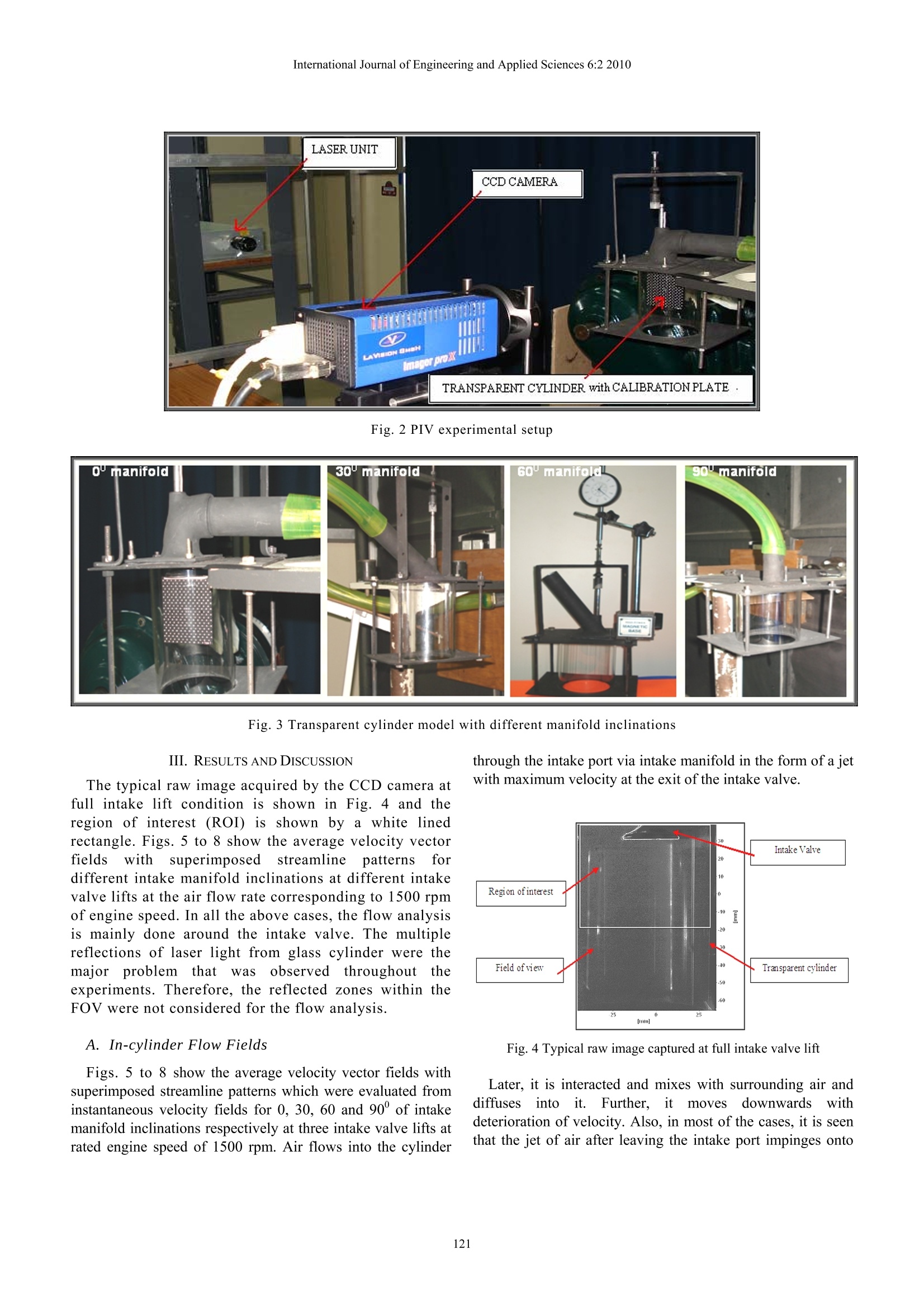
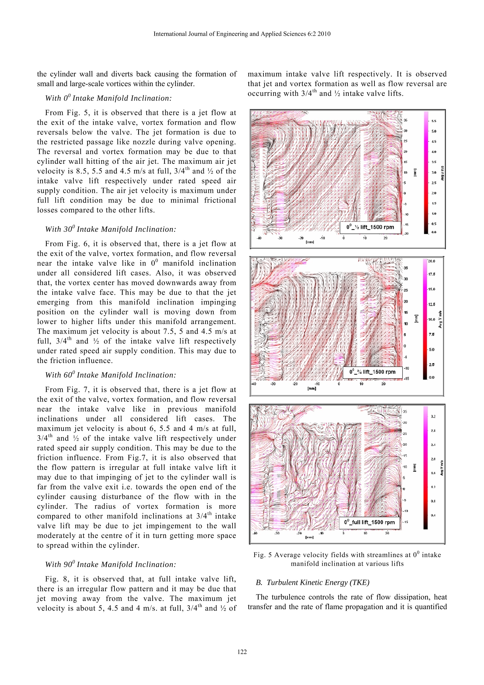
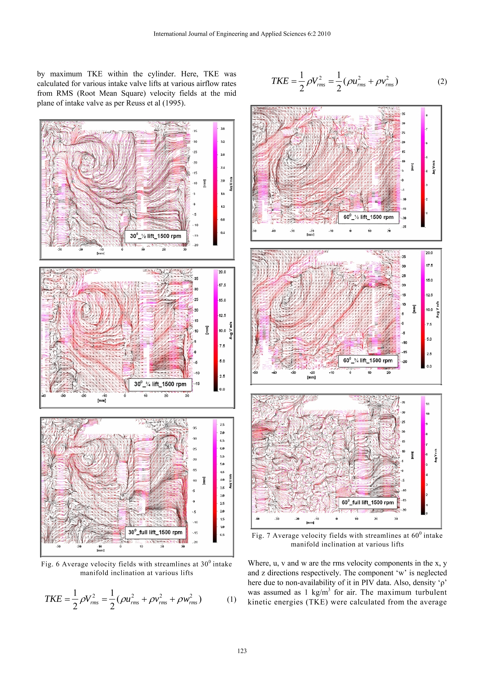
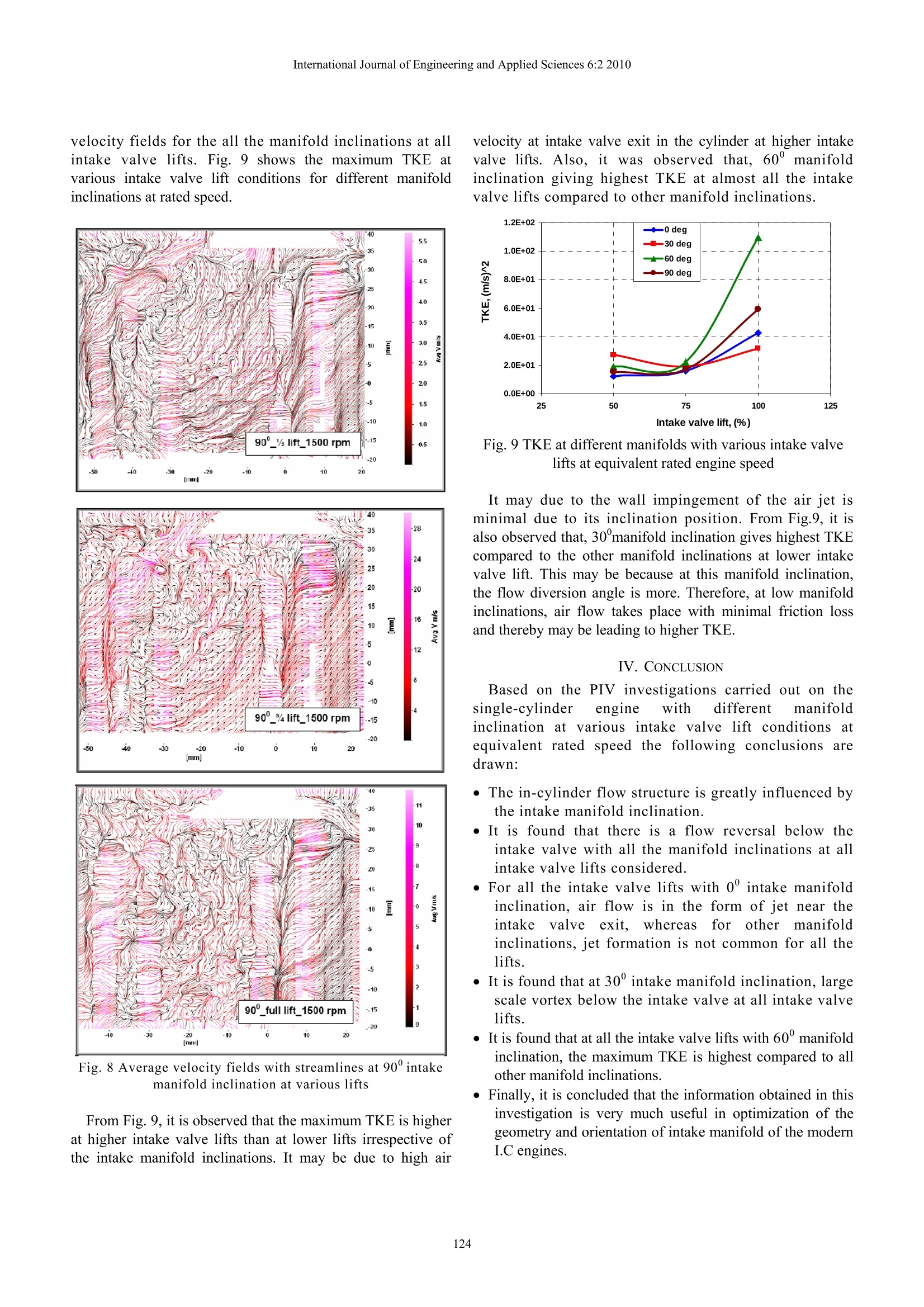
International Journal of Engineering and Applied Sciences 6:2 2010 Effect of Intake Manifold Inclination onIntake Valve Flow Characteristics of a SingleCylinder Engine using Particle ImageVelocimetry B. Murali Krishna, A. Bijucherian, and J. M. Mallikarjuna Abstract-In-cylinder flowffiielddstructureinaninternalcombustion (I.C) engine has a major influence on the combustion,emissionand performance characteristics.S.Fluidenters thecombustion chamber of an I.C engine through the intake manifoldwith high velocity. Then the kinetic energy of the fluid resulting inturbulence causes rapid mixing of fuel and air, if the fuel is injecteddirectly into the cylinder. With optimal turbulence, better mixing offuel and air is possible which leads to effective combustion. A goodknowledge of the flow field inside the cylinder of an I.Cengine is very much essential for optimization of the designof the combustion chamber for better performance especiallyin modern I.C engines like gasoline direct injection (GDI),homogeneous charge compression ignition (HCCI)engines.The main objective of this work is to study the in-cylinder fluid flow field characteristics of a single-cylinderengine to see the effect of intake manifold inclination atequivalent rated engine speed using Particle Imageelocimetry (PIV) under r vvarioussistaticintake valve liftconditions. To facilitate the PIV experiments, the metal cylinder ofthe engine was replaced by a transparent one. For every operatingtest condition,50 image pairs were captured and processed usingDAVIS software. From the results, it is seen that the in-cylinderflow structure is greatly influenced by the intake manifoldinclinations irrespective of intake valve lift. Maximum TurbulentKinetic Energy (TKE) was highest at full intake valve liftirrespective of the inclination. Also, the maximum TKE wasthe highest for 60° intake manifold inclination compared toother inclinations irrespective of the intake valve lift atequivalent rated engine speed. Finally, it is concluding thatthe analysis carried in this work is useful in predicting theflow and inturn optimizing combustion chamber of modernI.C engines. Keywords—In-cylinder flow field, Manifold inclination, PIV,Velocity. I. INTRODUCTION HE fluid motion in an internal combustion engine isinduced during the inductionprocess andlatermodified during the compression process. Intake chargeenters the combustion chamber through the intake manifold. ( Autors a re w ith I nternal Combustion E ngine L a boratory, Department o f Mechanical E n gineering, I n dian In s titute of T e chnology Madras, Che n nai,6000 3 6, I n dia (phone: 044-2257-4698;fax: ( 0 44-2257-4652; e-mail: murali2kindia@gmail.com, bcamace@gmail.com,jmmallik@iitm.ac.in). ) Then the kinetic energy of the fluid resulting in turbulencecauses rapid mixing of fuel and air, if the fuel is injecteddirectly into the cylinder. In-cylinder fluid motion governsthe flame propagation in spark-ignition engines, andcontrols the fuel-air mixing and premixed burning indiesel engines. Therefore, it is very much essential tounderstand the in-cylinder fluid motion thoroughly inorder to optimize the combustion chambers for themodern I.C engines like gasoline direct injection (GDI),homogeneous chargecompression ignition (HCCI)engines etc. Previously,Heywood(1998) has stated that generatingassignificant swirl and/or tumble motion inside theengine cylinder during the intake process was one of thepromising ways to obtain high in-cylinder turbulentintensity. Prasad (2000) reviewed the PIV studies andhad reported the basic components of PIV algorithms,opticalconsiderations.tracer particles, illuminatinglasers, recording hardware, typical errors associated andvector processing, etc. Hatschbach et al (2004) havedescribed their experiences with in-cylindermeasurement using PIV, mainly with air seeding andmultiple reflections on the glass liner. It reported thatthe PIV measurement was useful tool for evaluating in-cylinder flows especially when combined with numericalsimulation. Valentino et al (1993), Reeves et al (1999),Li et al (2001), Yasar et al(2006) and Stansfield et al(2007) have conducted PIV measurements on variousengines and reported that the flow structure changessubstantially along the cylinder length due toothegeometry of the intake valve port and the tumble motionwas generated during induction process. Also, reportedthat the increase in the air flow rate at higher enginespeed causes the vortex center to move right-upwardscompared to the lower engine speeds. Lee et al (1993)and Justhamn et al (2006) haveinvestigateddtheinstantaneous 2D velocity fields around the intake valveof an I.C engine under static and dynamic conditions bymeans of PIV. They have observed that for the givenintake valve lift and pressure drop across the intakevalve, the static analysis showed higher jet velocity thanthe dynamic analysis. Chung et al (1998) have studied the intake-generated, in-cylinder flow and subsequentcombustion ccharacteristicsiirn afour-valve.spark-ignition engine under a steady flow condition for intakeports with three different entry angles; 15, 20 and 25°using PIV. They have reported that the intake ports withlesser entry angles generate higher tumble strength thanat higher entry angles. They have observed that thestrong tumble motion resulted in15% decreaseincombustion duration. Nadarajah etal (1998) andAuriemma et al (2001) have carried out experimentalinvestigations using the Laser Doppler Anemometry(LDA) technique to study the engine in-cylinder flowcharacteristics. Their results showedthat the flowstructure during the intake was very much affected bythe intake valve lifts with the formation of up and downflows and a strong flow reversal below the intake valvegenerated during the intake closure period. Also, theaddition of swirl into the engine was altering the flowstructure, particularly below the intake valve. From the previous studies, it is clearly showing thatexperimental investigations are very much essential tostudy the effect of intake manifold inclinations on thein-cylinder flow field characteristics of an engine. Thiswork is aimed to study the in-cylinder flow fieldcharacteristics in a single-cylinder engine using PIVtechnique with different intake manifold inclinations atequivalent rated engine speed. II. EXPERIMENTAL SETUP AND PROCEDURE Figs. land 2 show the line diagram and pictorial viewof the PIV experimental setup respectively. The testengine cylinder was made of glass with the dimensionsof 87.5 mm bore and 110mm length. The glass cylinderwas mounted between two metal flat plates as shown intheFig.1. A hole waass made inthee top platecorresponding to the size and position of the intake portof the actual engine. Around this hole, a clampingarrangement was made to fix the inlet manifold atdifferent inclinations according to the requirement. Thebottom plate was provided with an openingcorresponding to the engine bore to discharge the air tothe atmosphere. Four intake manifolds with inclinationsof 0, 30, 60 and 90°with respect to horizontal planewere fabricated as shown in Fig.3. Then the intake valveWas fitteddon to the intake manifold.A screWarrangement was made to vary the intake valve lift.Intake manifold was connected to an air blower with avariable speed controller through a flexible hose. Anorifice flow meter was used to measure the rate of flowof supplied air to the cylinder. Fig. 1 Schematic of experimental setup The air supply was estimated corresponding to therated engine speed of 1500 rpm by assuming 90%volumetric efficiency. From this onwards it will becalled as equivalent rated engine speed Air flow rate andcorresponding image separation time (dt) are 0.0085kg/s and 18.51 us respectively.Throughouttheexperiments, the exhaust valve waskept closed. Tominimize the light reflections from the other metalsurfaces, all the metal surfaces were painted with blackcolor. All the other exposed metal surfaces other than atthe field of viewwere covered with black sheets.Calibration was done to determine the image size withrespect to the object size. The flow analysis was madeon a vertical plane passing through the center of theintake valve. The maximum intake valve lift consideredwas 7.6 mm and is of axi-symmetric poppet type. Theintakee valveelift wasadjustedmanuallyby usingadjustable screwarrangement and lift was measuredwith the help of dial gauge. The valve lifts consideredfor this study were 50, 75 and 100% of maximum valvelift for all the cases of intake manifold inclinations. During PIV experiments, the laser sheet was allowedto pass through the test section so that the flow field1magescan beecapturedbyai CCDccamera.Thephotograph and a schematic diagram of the experimentalsetup are shown in Figs. 1 and 2 respectively. Thecamera was positioned in front of the cylinder at thefield of view (FOV) perpendicular to the laser sheet.The FOV considered was 87.5x110 mm. Within this, theregion of interest (ROI) was selected for the flowanalysis later. The camera and laser triggering werecontrolled tby DAVIS software through aa PPCC. Theseeding particles of about one micron mean diameterwere generated by a particle generator and were mixedwith the intake supply air. The flow field analysis wasmade to evaluate the average velocity field, streamlinepatterns and maximum turbulent kinetic energy (TKE) atdifferent conditions. Fig. 2 PIV experimental setup Fig. 3 Transparent cylinder model with different manifold inclinations III. RESULTS AND DISCUSSION The typical raw image acquired by the CCD camera atfull intake lift condition is shown in Fig. 4 and theregion of interest (ROI) is shown by a white linedrectangle. Figs. 5 to 8 show the average velocity vectorfields withsuperimposedstreamline patterns fordifferent intake manifold inclinations at different intakevalve lifts at the air flow rate corresponding to 1500 rpmof engine speed. In all the above cases, the flow analysisis mainly done around the intake valve. The multiplereflections of laser light from glass cylinder were themajor problemn tthattwasobserved throughouttheexperiments. Therefore, the reflected zones within theFOV were not considered for the flow analysis. A. In-cylinder Flow Fields Figs. 5 to 8 show the average velocity vector fields withsuperimposed streamline patterns which were evaluated frominstantaneous velocity fields for 0, 30, 60 and 90°of intakemanifold inclinations respectively at three intake valve lifts atrated engine speed of 1500 rpm. Air flows into the cylinder through the intake port via intake manifold in the form of a jetwith maximum velocity at the exit of the intake valve. Fig. 4 Typical raw image captured at full intake valve lift Later, it is interacted and mixes with surrounding air anddiffusesintoit. Further, itmovesdownwards withdeterioration of velocity. Also, in most ofthe cases, it is seenthat the jet of air after leaving the intake port impinges onto the cylinder wall and diverts back causing the formation ofsmall and large-scale vortices within the cylinder. With 0"Intake Manifold Inclination: From Fig. 5, it is observed that there is a jet flow atthe exit of the intake valve, vortex formation and flowreversals below the valve. The jet formation is due tothe restricted passage like nozzle during valve opening.The reversal and vortex formation may be due to thatcylinder wall hitting of the air jet. The maximum air jetvelocity is 8.5, 5.5 and 4.5 m/s at full, 3/4h and of theintake valve lift respectively under rated speed airsupply condition. The air jet velocity is maximum underfull lift condition may be due to minimal frictionallosses compared to the other lifts. With 30' Intake Manifold Inclination: From Fig. 6, it is observed that, there is a jet flow atthe exit of the valve, vortex formation, and flow reversalnear the intake valve like in 0° manifold inclinationunder all considered lift cases. Also, it was observedthat, the vortex center has moved downwards away fromthe intake valve face. This may be due to that the jetemergingfromnthismanifoldinclinationnimpingingposition on the cylinder wall is moving down fromlower to higher lifts under this manifold arrangement.The maximum jet velocity is about 7.5, 5 and 4.5 m/s atfull, 3/4th and of the intake valve lift respectivelyunder rated speed air supply condition. This may due tothe friction influence. With 60' Intake Manifold Inclination: From Fig. 7, it is observed that, there is a jet flow atthe exit of the valve, vortex formation, and flow reversalneartheintake valve like in previous manifoldinclinations under allconsidered lift cases. Themaximum jet velocity is about 6, 5.5 and 4 m/s at full,3/4th and of the intake valve lift respectively underrated speed air supply condition. This may be due to thefriction influence. From Fig.7, it is also observed thatthe flow pattern is irregular at full intake valve lift itmay due to that impinging of jet to the cylinder wall isfar from the valve exit i.e. towards the open end of thecylinder causing disturbance of the flow with in thecylinder.The radius of vortex fformation ismorecompared to other manifold inclinations at 3/4th intakevalve lift may be due to jet impingement to the wallmoderately at the centre of it in turn getting more spaceto spread within the cylinder. With 90° Intake Manifold Inclination: Fig. 8, it is observed that, at full intake valve lift,there is an irregular flow pattern and it may be due thatjet moving away from the valve. The maximum jetvelocity is about 5, 4.5 and 4 m/s. at full, 3/4th and of maximum intake valve lift respectively. It is observedthat jet and vortex formation as well as flow reversal areoccurring with 3/4th and %intake valve lifts. Fig. 5 Average velocity fields with streamlines at 0° intakemanifold inclination at various lifts B. Turbulent Kinetic Energy (TKE) The turbulence controls the rate of flow dissipation, heattransfer and the rate of flame propagation and it is quantified Fig. 7 Average velocity fields with streamlines at 60° intakemanifold inclination at various lifts velocity fields for the all the manifold inclinations at allintake valve lifts. Fig. 9 shows the maximum TKE atvarious intake valve lift conditions for different manifoldinclinations at rated speed. Fig. 8 Average velocity fields with streamlines at 90°intakemanifold inclination at various lifts From Fig. 9, it is observed that the maximum TKE is higherat higher intake valve lifts than at lower lifts irrespective ofthe intake manifold inclinations. It may be due to high air velocity at intake valve exit in the cylinder at higher intakevalve lifts. Also, it was observed that, 60° manifoldinclination giving highest TKE at almost all the intakevalve lifts compared to other manifold inclinations. Fig. 9 TKE at different manifolds with various intake valvelifts at equivalent rated engine speed It may due to the wall impingement of the air jet isminimal due to its inclination position. From Fig.9, it isalso observed that, 30manifold inclination gives highest TKEcompared to the other manifold inclinations at lower intakevalve lift. This may be because at this manifold inclination,the flow diversion angle is more. Therefore, at low manifoldinclinations, air flow takes place with minimal friction lossand thereby may be leading to higher TKE. IV. CONCLUSION Based on the PIV investigations carried out on thesingle-cylinder engine with different manifoldinclination at various intake valve lift conditions atequivalent rated speed the following conclusions aredrawn: · The in-cylinder flow structure is greatly influenced bythe intake manifold inclination. ● It is found that there is a flow reversal below theintake valve with all the manifold inclinations at allintake valve lifts considered. For all the intake valve lifts with 0° intake manifoldinclination, air flow is in the form of jet near theintake valve exit, whereas for other manifoldinclinations, jet formation is not common for all thelifts. It is found that at 30°intake manifold inclination, largescale vortex below the intake valve at all intake valvelifts. It is found that at all the intake valve lifts with 60°manifoldinclination, the maximum TKE is highest compared to allother manifold inclinations. Finally, it is concluded that the information obtained in thisinvestigation is very much useful in optimization of thegeometry and orientation of intake manifold of the modernI.C engines. ( REFERENCES ) ( [1] A jay K. P r asad ( 2 000),“Particle image v e locimetry-review”,University of Delaware, Newark, DE 1 9716-3140, USA, Current Science, Vol.79,NO. 1 ,10. ) ( [2] C hen, A., A . Veshagh a n d S. Wallace, (1998), “ I ntake FlowPredictions of a Transparent DI Diesel E ngine", SAE p a per 981020. ) ( [3] H eywood, J. 1. B., (1988), I Internal Combustion Engine Fundamentals, McGraw-Hill, Singapore, 1 9 88. ) ( [4] L ee J anghee and F a rrell P . V., (1993), “ Intake Valve Flow Measurements s of an IC Engine Using P article imageVelocimetry”, SAE Paper No. 930480. ) ( [5] Li, Y., H. Zhao, Z. Peng and N. Ladommatos,(2001),“Particleimage velocimetry m e asurement of i n-cylinder flo w in inte r nalcombustion e ngines experiment and fl o w structure an a lysis”, P roc I nstn. Mech E ngrs Vol 2 16 Part D. ) ( [6] Nadarajah S , B a labani S , T i ndal M . J and M Y ianneskis (1998),“The e ffect of swirl on the annular flow past an axisymmetric poppet v alve”, P roc I M ech E - Vol 212, P a rt C. ) ( [7]7 ] Per Hatschbach, Jan Novotny a nd P avel B aumruk, ( 2 004),“Measurement of Flow in M odel of Internal Combustion Engine Cylinder using PIV”, Research Center project L N00B073 of M inistry o f Education, Czech R epublic. ) ( [8] R eeves, M., M.J H a ste and N.A Halliwell, (1 9 99),“Ba r rel swi r lbreakdown i n s p ark-ignition engines: insights from particleimage v elocimetry measurements” A pplied O ptics L aboratory,Leicestershire, UK, Proc I MechE, V ol 213, Part D. ) ( [9] Valentino Gerardo, Duane K aufman and Patrick F a rrell ( 1993),“Intake Valve Flow M easurements U s ing PIV”, SAE Paper No.932700. ) ( [10] R euss L . David, Tang-Wei Kuo, Bahram Khalighi, D a n Haworth, and M artin R osalik, Particle Image Velocimetry Measurements i n a High-Swirl E ngine used f o r E v aluation of C o mputational Fluid Dynamics C alculations, SAE Paper No.952381, 1 9 95. ) ( [ 11 ] Heywood J o hn B , Internal C ombustion E n gine Fundamentals, p u b: M cGraw Hill International Editions, 1988. [12] | I DAVIS - Software Manuals, L a vision, Germany, 2006. ) ( [ 1 3] M urali Krishna. B a n d J. M. Mallikarjuna, Intake valve flo w analysis in adirect injection diese l engine u sing p article image velocimetry, proceeding o f the 2 "d I nternational Conference o n Recent a d vances in experimental fluid mechanics(RAEFM-2008), March 3-6,2008. ) ( [14] M urali Krishna. B a n d J. M . M a l likarjuna, Optical Di a gnosis of Flowthrough the Intake Valve in a D irect I njection Diesel Engine, p roceedings o f the 15Th ISME In t erna t ional Conference on n ew hori z ons of Mechanical Engineering (ISME-2008), March 18-20, 2008. ) ( [15] M urali K rishna. B and J. M. Mallikarjuna, F low through intake v alve of a d irect i njection d iesel e ngine - A pr e liminary stu d y usin g part i cle i mage v elocimetry, p roceedings o f the I nternational Conference on M echanical E ngineering (ICME2008), J ohor B ahru, Malaysia, ISBN: 97-98-2963-59-2, May21-23,2008. ) ( [16] M urali Krishna, B . and J. M. Mallikarjuna (2008, July), Effect of Engine S peed on I n take V a lve Flow Ch a r a cteristics o f a D i esel E n gine- A n Analysis U sing P a rticle I mage Velocimetry, pr o ceedings of the Fir s tInternationa l Conference on Emerging T rends i n Engineering a nd T echnology ( ICETE T 2008), N o . 9 7 8-0-7695-3267-7/08 I E EE, July 16- 1 8, 2008, India. ) ( [17] A uriemma, M., F . E . Corcione, U . D i M a rtino and G. Valentino, ( 2 001), “Analysis of the Intake Flow in a Diesel Engine Head Using Dynamic Steady F low Co n ditions”, Istituto Motori, CNR, N aples - I taly, 2001- 01-1307,SAE. ) ( [18] P hil Stansfield, Graham W igley, Tim Justham, J u lian Catto and Graham P itcher, (2007), “ PIV analysis of in-cylinder flow structures over a rangeof realistic engine speeds” , Exp Fluids 43:135- 14 6, Springer. ) ( [ 1 9] Y asar, A . , B. Sahin, H . Akilli and K. Aydin, (2006), “Effect of inlet porton the flow i n t he cylinder of an internal combustion engine”, CukurovaUniversity , Adana, Turkey, Proc . I MechE Vol. 2 20 P a rt C : J. M echanical Engineering Science. ) i
确定
还剩5页未读,是否继续阅读?

产品配置单


北京欧兰科技发展有限公司为您提供《单缸,发动机,进气歧管,倾角,进气门中流动特性,速度场,速度矢量场检测方案(粒子图像测速)》,该方案主要用于其他中流动特性,速度场,速度矢量场检测,参考标准--,《单缸,发动机,进气歧管,倾角,进气门中流动特性,速度场,速度矢量场检测方案(粒子图像测速)》用到的仪器有德国LaVision PIV/PLIF粒子成像测速场仪、汽车发动机多参量测试系统、Imager LX PIV相机
推荐专场


相关方案
更多
该厂商其他方案
更多