


方案详情
文
采用LaVision的sCMOS型CCD相机和200毫焦的PIV激光器,采用水下潜望镜形式拍照,采用荧光示踪粒子成像测速(PIV )方法跟踪掠过水体表面薄膜流场的涡核。
方案详情

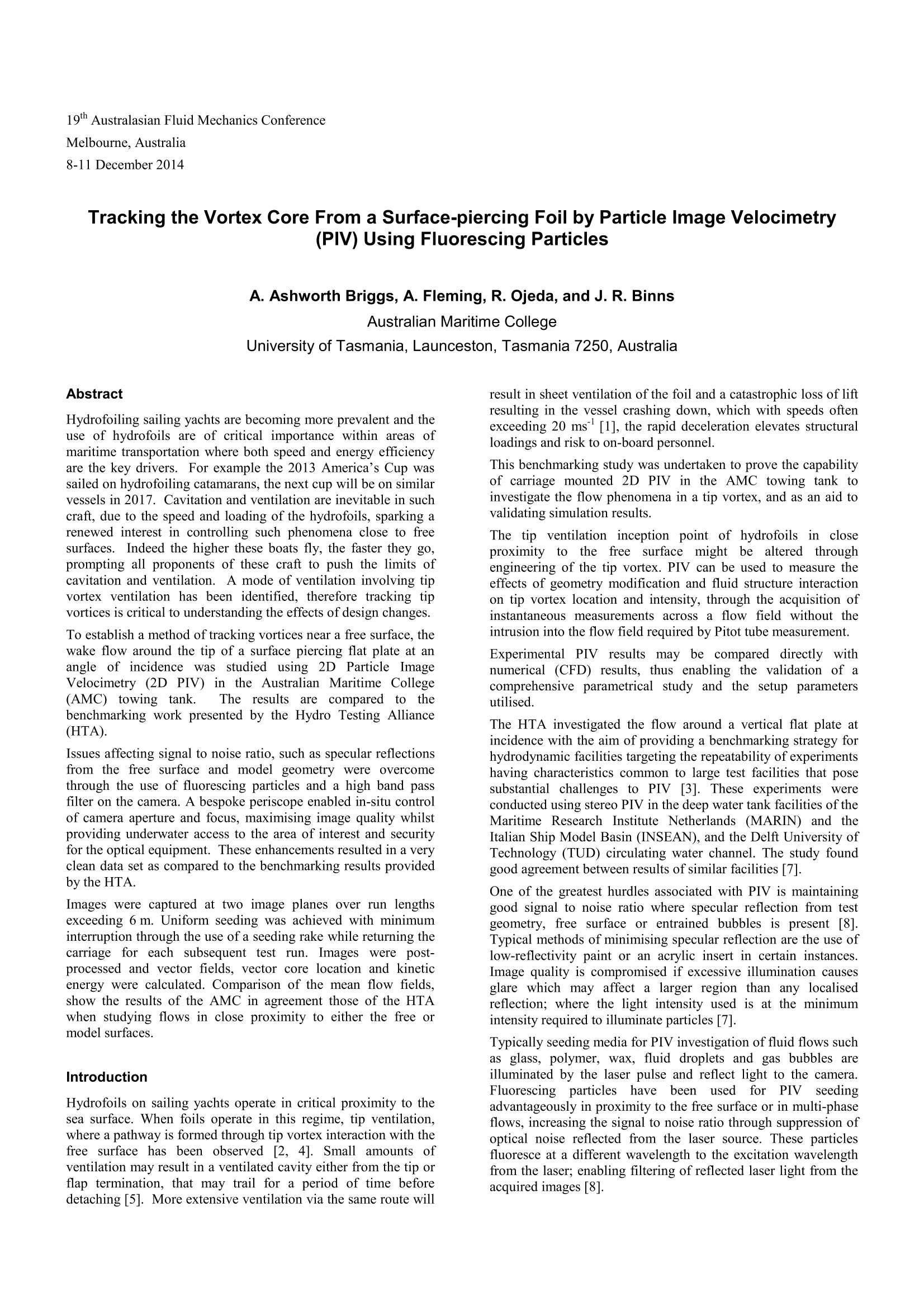
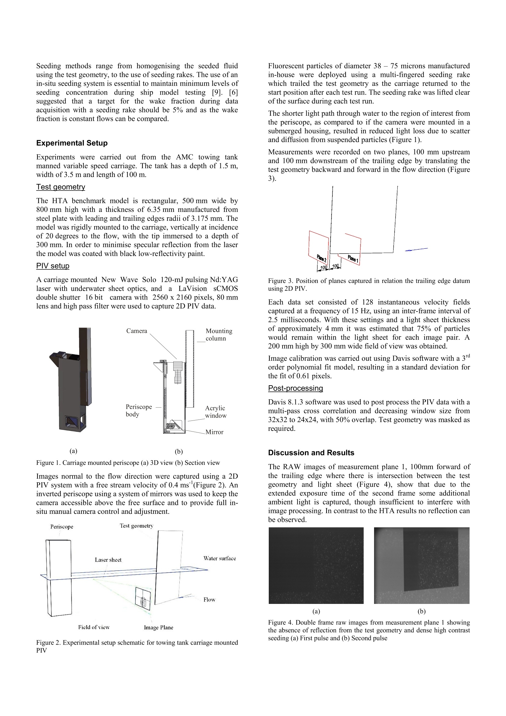
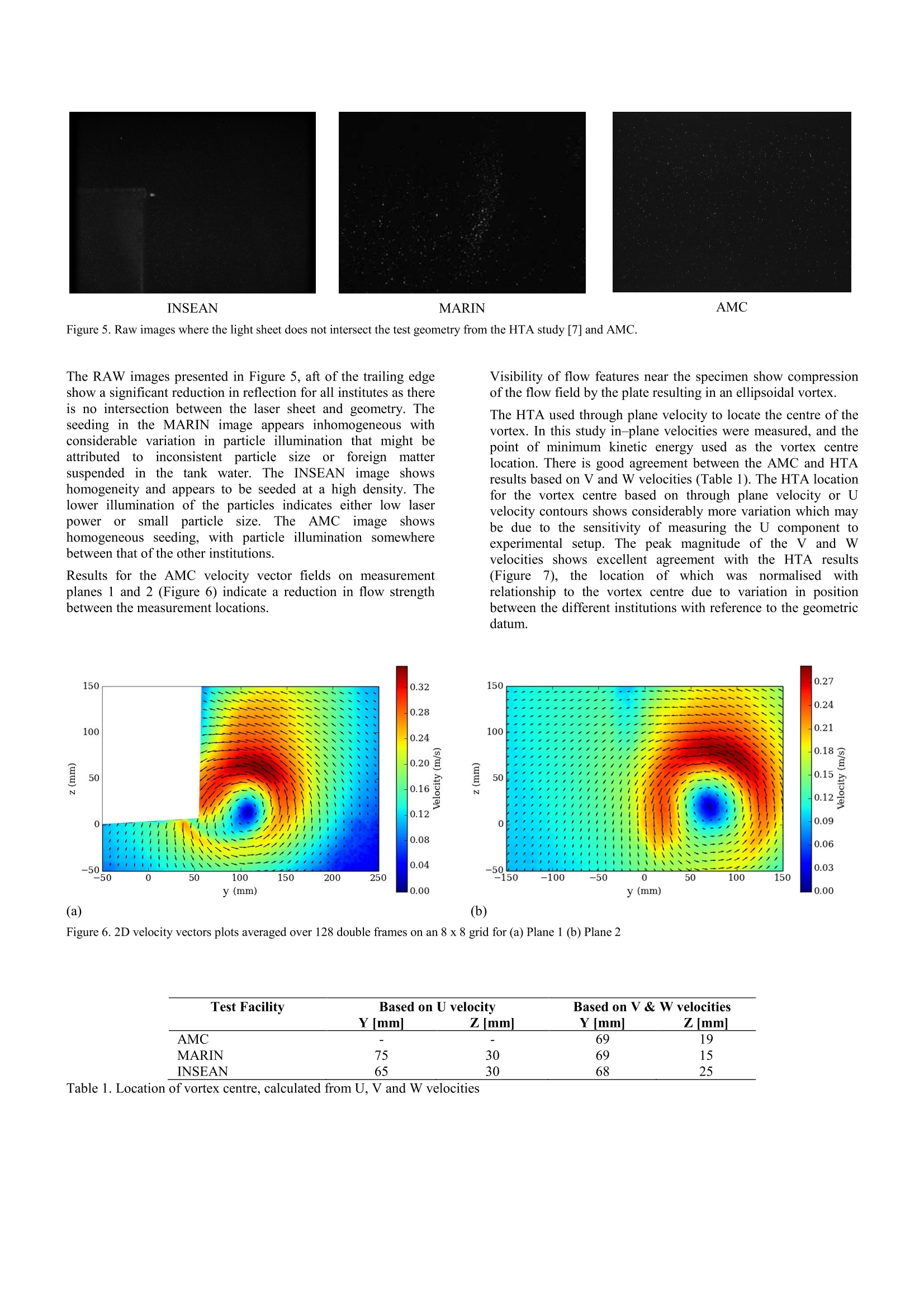
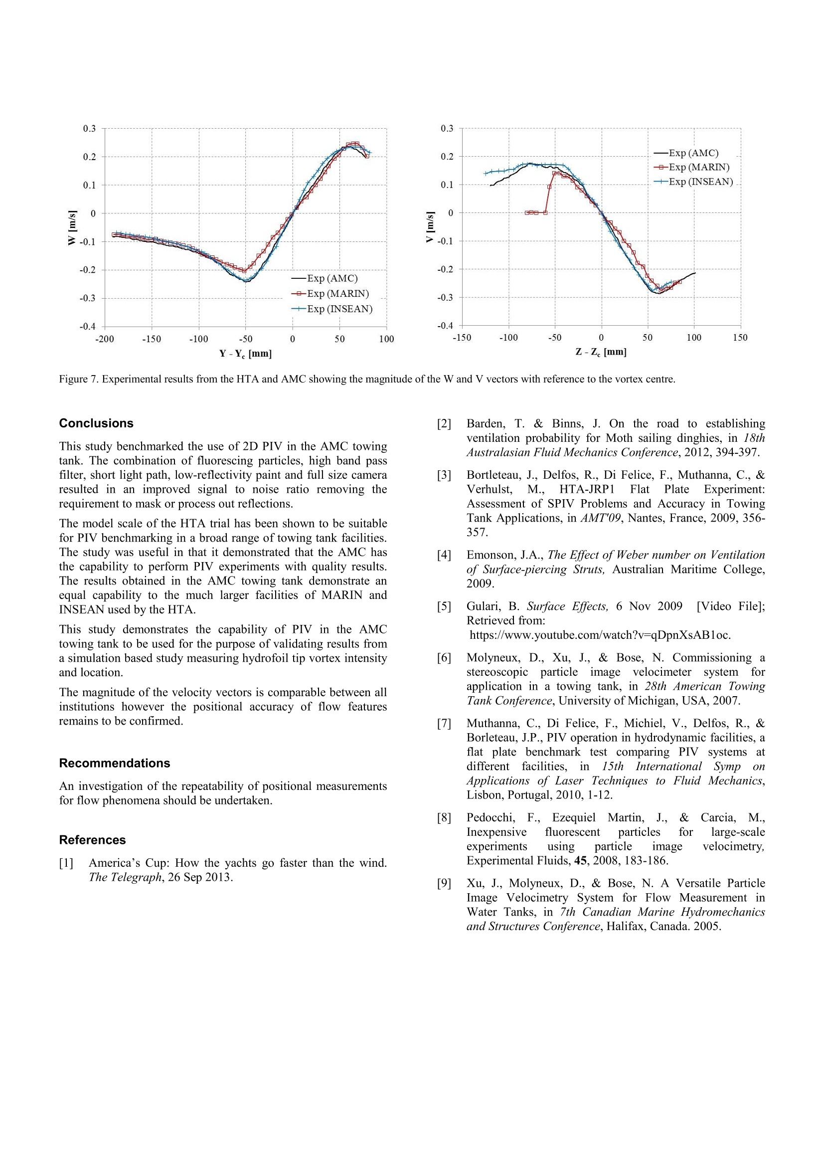
19th Australasian Fluid Mechanics ConferenceMelbourne, Australia8-11 December 2014 Tracking the Vortex Core From a Surface-piercing Foil by Particle Image Velocimetry(PIV) Using Fluorescing Particles A. Ashworth Briggs, A. Fleming,R. Ojeda, and J. R. Binns Australian Maritime College University of Tasmania, Launceston, Tasmania 7250, Australia Hydrofoiling sailing yachts are becoming more prevalent and theuse of hydrofoils are of critical importance within areas ofmaritime transportation where both speed and energy efficiencyare the key drivers. For example the 2013 America’s Cup wassailed on hydrofoiling catamarans, the next cup will be on similarvessels in 2017. Cavitation and ventilation are inevitable in suchcraft, due to the speed and loading of the hydrofoils, sparking arenewed interest in controlling such phenomena close to freesurfaces. Indeed the higher these boats fly, the faster they go,prompting all proponents of these craft to push the limits ofcavitation and ventilation. A mode of ventilation involving tipvortex ventilation has been identified, therefore tracking tipvortices is critical to understanding the effects of design changes. To establish a method of tracking vortices near a free surface, thewake flow around the tip of a surface piercing flat plate at an’ir ..angle of incidence was studied using 2D Particle ImageVelocimetry (2D PIV) in the Australian Maritime College(AMC) towing tank. The results are compared to thebenchmarking work presented by the Hydro Testing Alliance(HTA). Issues affecting signal to noise ratio, such as specular reflectionsfrom the free surface and model geometry were overcomethrough the use of fluorescing particles and a high band passfilter on the camera. A bespoke periscope enabled in-situ controlof camera aperture and focus, maximising image quality whilstproviding underwater access to the area of interest and securityfor the optical equipment. These enhancements resulted in a veryclean data set as compared to the benchmarking results providedby the HTA. Images were captured at two image planes over run lengthsexceeding 6 m. Uniform seeding was achieved with minimuminterruption through the use of a seeding rake while returning thecarriage for each subsequent test run. Images were post-processed and vector fields, vector core location and kineticenergy were calculated. Comparison of the mean flow fields,show the results of the AMC in agreement those of the HTAwhen studying flows in close proximity to either the free ormodel surfaces. Introduction Hydrofoils on sailing yachts operate in critical proximity to thesea surface. When foils operate in this regime, tip ventilation,where a pathway is formed through tip vortex interaction with thefree surface has been observed [2, 4]. Small amounts ofventilation may result in a ventilated cavity either from the tip orflap termination, that may trail for a period of time beforedetaching [5]. More extensive ventilation via the same route will result in sheet ventilation of the foil and a catastrophic loss of liftresulting in the vessel crashing down, which with speeds oftenexceeding 20 ms [1], the rapid deceleration elevates structuralloadings and risk to on-board personnel. This benchmarking study was undertaken to prove the capabilityof carriage mounted 2D PIV in the AMC towing tank toinvestigate the flow phenomena in a tip vortex, and as an aid tovalidating simulation results. The tip ventilation inception point of hydrofoils in closeproximity to the free surface might be altered throughengineering of the tip vortex. PIV can be used to measure theeffects of geometry modification and fluid structure interactionon tip vortex location and intensity, through the acquisition ofinstantaneous measurements across a flow field without theintrusion into the flow field required by Pitot tube measurement. Experimental PIV results may be compared directly withnumerical (CFD) results, thus enabling the validation of acomprehensive parametrical study and the setup parametersutilised. The HTA investigated the flow around a vertical flat plate atincidence with the aim of providing a benchmarking strategy forhydrodynamic facilities targeting the repeatability of experimentshaving characteristics common to large test facilities that posesubstantial challenges to PIV [3]. These experiments wereconducted using stereo PIV in the deep water tank facilities of theMaritime Research Institute Netherlands (MARIN) and theItalian Ship Model Basin (INSEAN), and the Delft University ofTechnology (TUD) circulating water channel. The study foundgood agreement between results of similar facilities [7]. One of the greatest hurdles associated with PIV is maintaininggood signal to noise ratio where specular reflection from testgeometry, free surface or entrained bubbles is present [8].Typical methods of minimising specular reflection are the use oflow-reflectivity paint or an acrylic insert in certain instances.Image quality is compromised if excessive illumination causesglare which may affect a larger region than any localisedreflection; where the light intensity used is at the minimumintensity required to illuminate particles [7]. Typically seeding media for PIV investigation of fluid flows suchas glass, polymer, wax, fluid droplets and gas bubbles areilluminated by the laser pulse and reflect light to the camera.Fluorescing particleshavebeennusedforr PIVseedingadvantageously in proximity to the free surface or in multi-phaseflows, increasing the signal to noise ratio through suppression ofoptical noise reflected from the laser source. These particlesfluoresce at a different wavelength to the excitation wavelengthfrom the laser; enabling filtering of reflected laser light from theacquired images [8]. Seeding methods range from homogenising the seeded fluidusing the test geometry, to the use of seeding rakes. The use of anin-situ seeding system is essential to maintain minimum levels ofseeding concentration during ship model testing[9]. [6]suggested that a target for the wake fraction during dataacquisition with a seeding rake should be 5% and as the wakefraction is constant flows can be compared. Experimental Setup Experiments were carried out from the AMC towing tankmanned variable speed carriage. The tank has a depth of 1.5 m,width of 3.5 m and length of 100 m. Test geometry The HTA benchmark model is rectangular, 500 mm wide by800 mm high with a thickness of 6.35 mm manufactured fromsteel plate with leading and trailing edges radii of 3.175 mm. Themodel was rigidly mounted to the carriage, vertically at incidenceof 20 degrees to the flow, with the tip immersed to a depth of300 mm. In order to minimise specular reflection from the laserthe model was coated with black low-reflectivity paint. PIV setup A carriage mounted New Wave Solo 120-mJ pulsing Nd:YAGlaser with underwater sheet optics, and1 a2 LaVision sCMOSdouble shutter 16 bit camera with 2560x 2160 pixels, 80 mmlens and high pass filter were used to capture 2D PIV data. Figure 1. Carriage mounted periscope (a) 3D view (b) Section view Images normal to the flow direction were captured using a 2DPIV system with a free stream velocity of 0.4 ms (Figure2). An+msinverted periscope using a system of mirrors was used to keep thecamera accessible above the free surface and to provide full in-situ manual camera control and adjustment. Figure2. Experimental setup schematic for towing tank carriage mountedPIV Fluorescent particles of diameter 388--775 microns manufacturedin-house were deployed using a multi-fingered seeding rakewhich trailed the test geometry as the carriage returned to thestart position after each test run. The seeding rake was lifted clearof the surface during each test run. The shorter light path through water to the region of interest fromthe periscope, as compared to if the camera were mounted in asubmerged housing, resulted in reduced light loss due to scatterand diffusion from suspended particles (Figure 1). Measurements were recorded on two planes, 100 mm upstreamand 100 mm downstream of the trailing edge by translating thetest geometry backward and forward in the flow direction (Figure3). Figure 3. Position of planes captured in relation the trailing edge datumusing 2D PIV. Each data set consisted of 128 instantaneous velocity fieldscaptured at a frequency of 15 Hz, using an inter-frame interval of2.5 milliseconds. With these settings and a light sheet thicknessof approximately 4 mm it was estimated that 75% of particleswould remain within the light sheet for each image pair. A200 mm high by 300 mm wide field of view was obtained. Image calibration was carried out using Davis software with a 3order polynomial fit model, resulting in a standard deviation forthe fit of 0.61 pixels. Post-processing Davis 8.1.3 software was used to post process the PIV data with amulti-pass cross correlation and decreasing window size from32x32 to 24x24, with 50% overlap. Test geometry was masked asrequired. Discussion and Results The RAW images of measurement plane 1, 100mm forward ofthe trailing edge where there is intersection between the testgeometry and light sheet (Figure 4), show that due to theextended exposure time of the second frame some additionalambient light is captured, though insufficient to interfere withimage processing. In contrast to the HTA results no reflection canbe observed. (a) (b) Figure 4. Double frame raw images from measurement plane 1 showingthe absence of reflection from the test geometry and dense high contrastseeding (a) First pulse and (b) Second pulse INSEAN MARIN AMC Figure 5. Raw images where the light sheet does not intersect the test geometry from the HTA study [7] and AMC. Figure 6. 2D velocity vectors plots averaged over 128 double frames on an 8x 8 grid for (a) Plane 1 (b) Plane 2 Test Facility Based on U velocity Based on V& W velocities Ymm] Zmm Y[mm] Zmm AMC MARIN INSEAN Table 1. Location of vortex centre, calculated from U, V and W velocities 0.3 0.3 Conclusions This study benchmarked the use of 2D PIV in the AMC towingtank. The combination of fluorescing particles, high band passfilter, short light path, low-reflectivity paint and full size cameraresulted in an improved signal to noise ratio removing therequirement to mask or process out reflections. The model scale of the HTA trial has been shown to be suitablefor PIV benchmarking in a broad range of towing tank facilities.The study was useful in that it demonstrated that the AMC hasthe capability to perform PIV experiments with quality results.The results obtained in the AMC towing tank demonstrate anequal capability to the much larger facilities of MARIN andINSEAN used by the HTA. This study demonstrates the capability of PIV in the AMCtowing tank to be used for the purpose of validating results froma simulation based study measuring hydrofoil tip vortex intensityand location. The magnitude of the velocity vectors is comparable between allinstitutions however the positional accuracy of flow featuresremains to be confirmed. Recommendations An investigation of the repeatability of positional measurementsfor flow phenomena should be undertaken. References 1] America’s Cup: How the yachts go faster than the wind.yaqThe Telegraph, 26 Sep2013. 2] Barden, T. & Binns, J. On the road to establishingventilation probability for Moth sailing dinghies, in 18thAustralasian Fluid Mechanics Conference, 2012, 394-397. 3] Bortleteau, J., Delfos, R., Di Felice, F., Muthanna, C., &Verhulst.t, M.,HTA-JRP1 FlattPlate Experiment:Assessment of SPIV Problems and Accuracy in TowingTank Applications, in AMT'09, Nantes, France, 2009, 356-357. 4]Emonson, J.A., The Effect of Weber number on Ventilationof Surface-piercing Struts, Australian Maritime College,2009. 5] Gulari, B. Surface Effects, 6 Nov 2009 [Video Filel:Retrieved from:https://www.youtube.com/watch?v=qDpnXsAB1oc. [6] Molyneux, D., Xu, J., & Bose, N. Commissioning astereoscooppiicc particcle1einimageevelocimeter systemforapplication in a towing tank, in 28th American TowingTank Conference, University of Michigan, USA, 2007. 7 Muthanna, C., Di Felice, F., Michiel, V., Delfos, R., &Borleteau, J.P., PIV operation in hydrodynamic facilities, aflat plate benchmark test comparing PIV systems atdifferent facilities, in15th InternationalSymp oi01Applications of Laser Techniques to Fluid Mechanics,Lisbon, Portugal, 2010, 1-12. ( [8] Pedocchi, F F.. Ezequiel e l Martin, J..,. & .C(arcia, M.. Inexpensive fluorescent particles for large-scale experiments using particle image velocimetry, Experimental Fluids,45,2008,183-186. ) [9] Xu, J., Molyneux, D., & Bose, N. A Versatile ParticleImage Velocimetry System for Flow Measurement inWater Tanks, in 7th Canadian Marine Hydromechanicsand Structures Conference, Halifax, Canada. 2005. Hydrofoiling sailing yachts are becoming more prevalent and the use of hydrofoils are of critical importance within areas of maritime transportation where both speed and energy efficiency are the key drivers. For example the 2013 America’s Cup was sailed on hydrofoiling catamarans, the next cup will be on similar vessels in 2017. Cavitation and ventilation are inevitable in such craft, due to the speed and loading of the hydrofoils, sparking a renewed interest in controlling such phenomena close to free surfaces. Indeed the higher these boats fly, the faster they go, prompting all proponents of these craft to push the limits of cavitation and ventilation. A mode of ventilation involving tip vortex ventilation has been identified, therefore tracking tip vortices is critical to understanding the effects of design changes. To establish a method of tracking vortices near a free surface, the wake flow around the tip of a surface piercing flat plate at an angle of incidence was studied using 2D Particle ImageVelocimetry (2D PIV) in the Australian Maritime College (AMC) towing tank. The results are compared to the benchmarking work presented by the Hydro Testing Alliance (HTA). Issues affecting signal to noise ratio, such as specular reflections from the free surface and model geometry were overcome through the use of fluorescing particles and a high band pass filter on the camera. A bespoke periscope enabled in-situ control of camera aperture and focus, maximising image quality whilst providing underwater access to the area of interest and security for the optical equipment. These enhancements resulted in a very clean data set as compared to the benchmarking results provided by the HTA. Images were captured at two image planes over run lengths exceeding 6 m. Uniform seeding was achieved with minimum interruption through the use of a seeding rake while returning the carriage for each subsequent test run. Images were postprocessed and vector fields, vector core location and kinetic energy were calculated. Comparison of the mean flow fields, show the results of the AMC in agreement those of the HTA when studying flows in close proximity to either the free or model surfaces.
确定
还剩2页未读,是否继续阅读?

产品配置单


北京欧兰科技发展有限公司为您提供《掠过水体表面薄膜中速度场检测方案(粒子图像测速)》,该方案主要用于其他中速度场检测,参考标准--,《掠过水体表面薄膜中速度场检测方案(粒子图像测速)》用到的仪器有德国LaVision PIV/PLIF粒子成像测速场仪、Imager sCMOS PIV相机、LaVision DaVis 智能成像软件平台
推荐专场


CCD相机/影像CCD
更多


相关方案
更多
该厂商其他方案
更多