


方案详情
文
Increasingly smaller electronics requires improvement in performance of cooling systems to keep it operating
reliably. We present herein a novel experimental study of convective heat transfer in serpentine
microchannels with segmented liquid–liquid emulsions. It is demonstrated that this concept yields significant
Nusselt number enhancement in microchannel heat sinks compared to that obtained using single
phase liquid cooling. Laser Induced Fluorescence (LIF) is employed to measure temperature of the coolant
with and without droplets, and micro-PIV is used to determine velocity field. For the segmented flow, up
to four-fold increase of the Nusselt number was observed compared to pure water flow.
方案详情

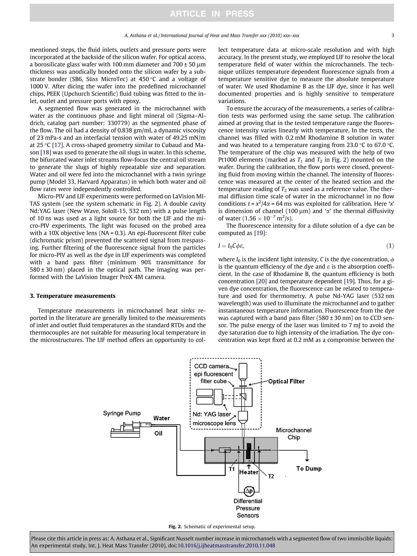
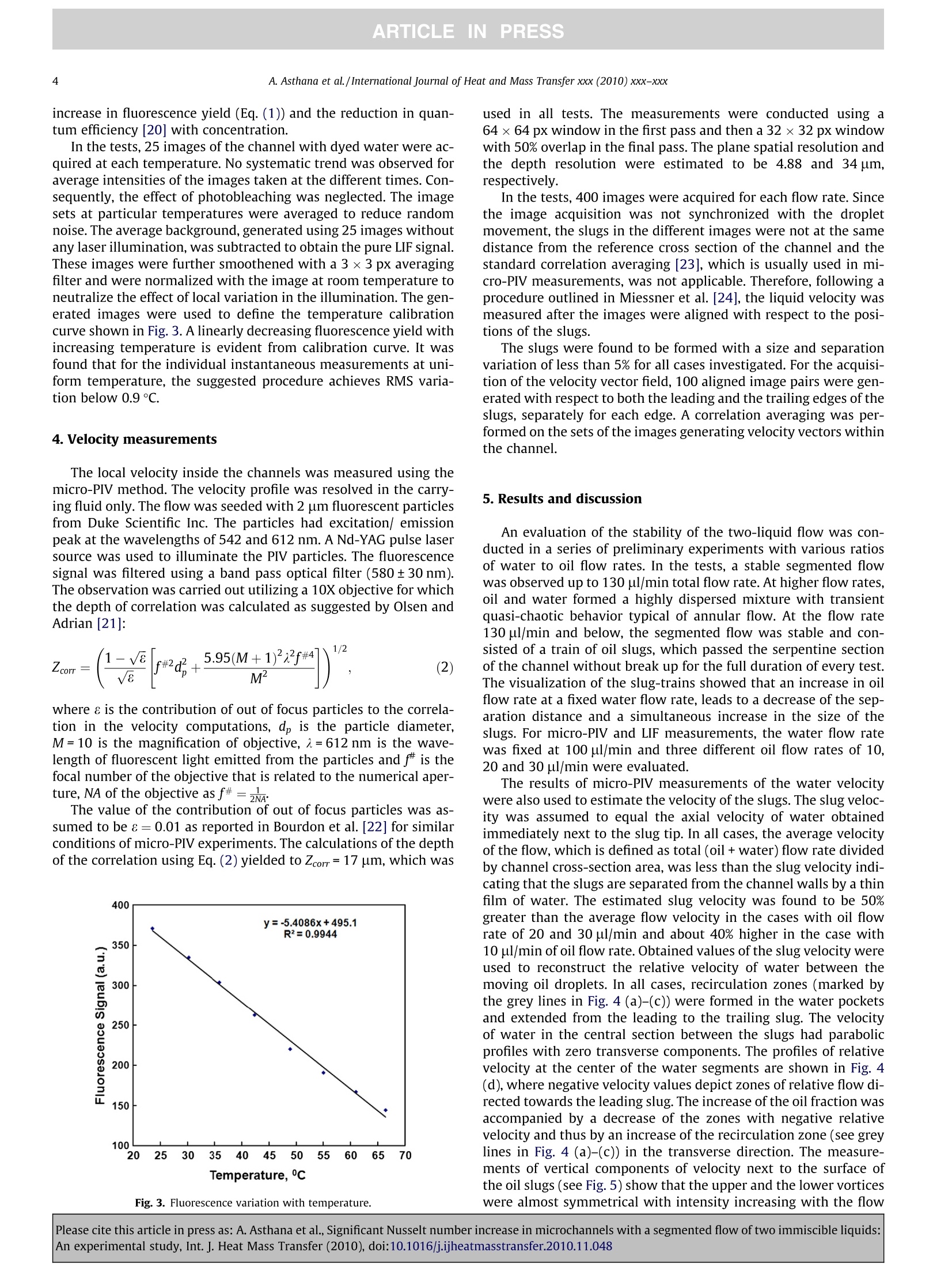
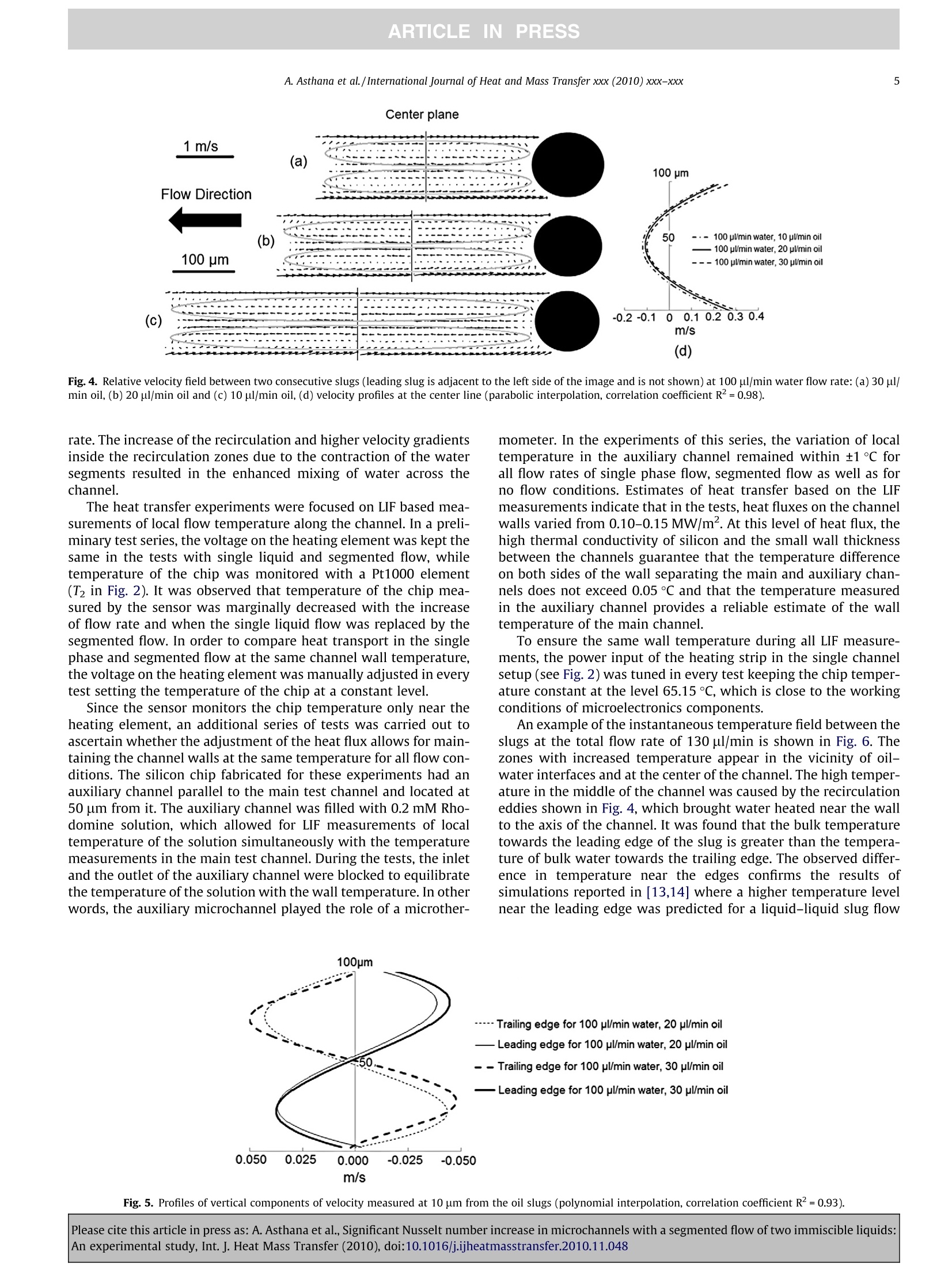
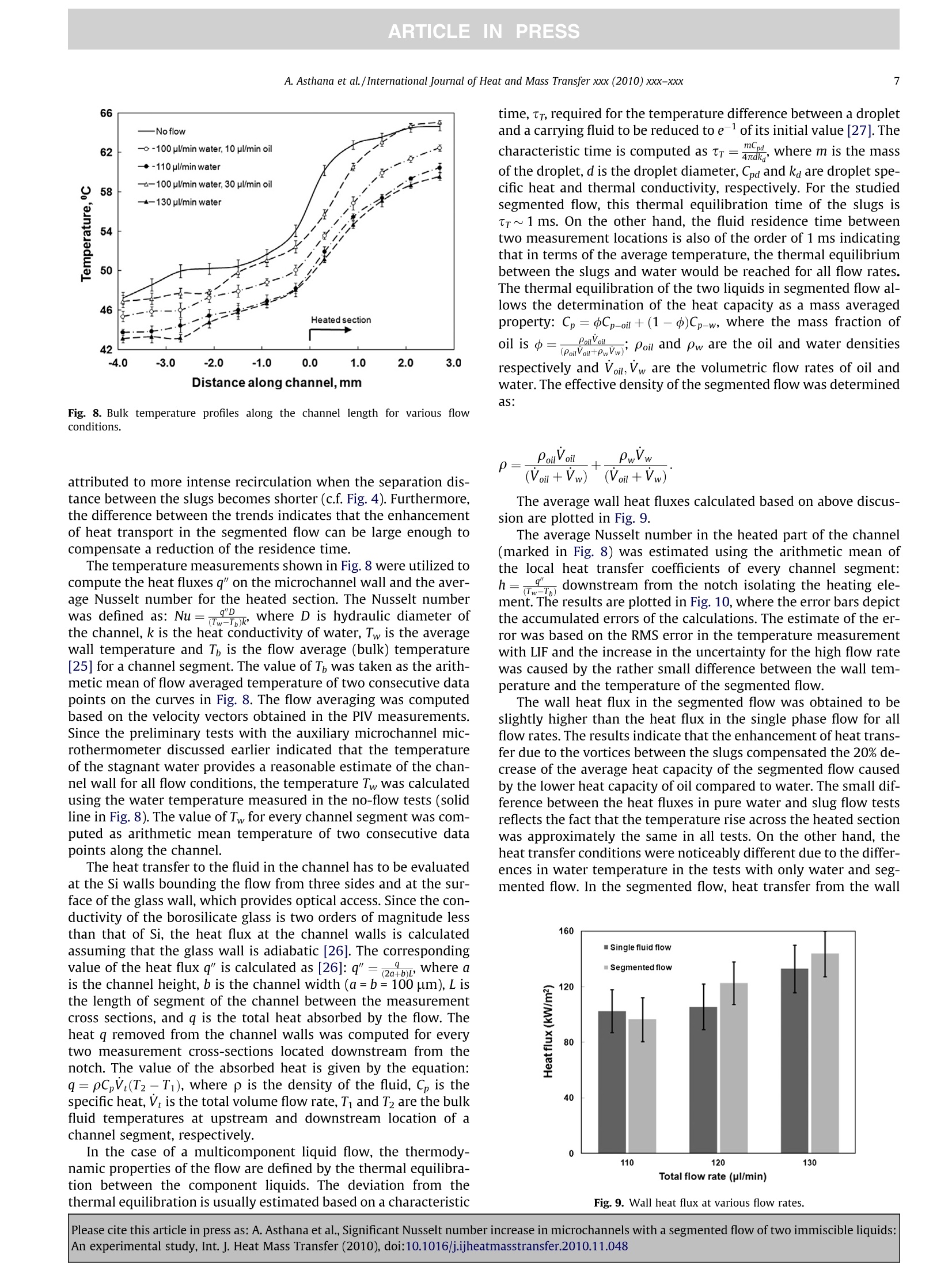
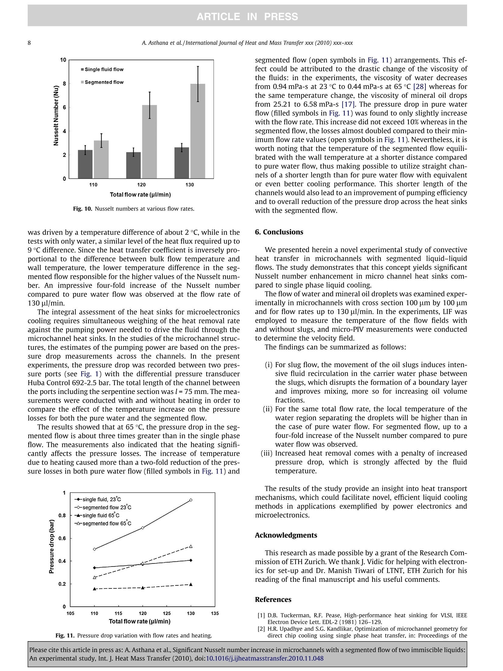
ARTICLEE INPRESSInternational Journal of Heat and Mass Transfer xxx (2010) XXX-XXX ARTICLEINPRESSA. Asthana et al./International Journal of Heat and Mass Transfer xxx (2010) xxx-xxx2 Contents lists available at ScienceDirect International Journal of Heat and Mass Transfer ELSEVIER journal homepage: www.elsevier.com/locate/ijhmt Significant Nusselt number increase in microchannels with a segmented flow oftwo immiscible liquids: An experimental study Ashish Asthana, Igor Zinovik, Christian Weinmueller, Dimos Poulikakos * Laboratory for Thermodynamics in Emerging Technologies, Department of Mechanical and Process Engineering, ETH Zurich, Zurich 8092, Switzerland ARTICL EIN F O A BSTRAC T Article history:Received 18 September 2010Received in revised form 23 October 2010Accepted 23 October 2010Available online xxxx Increasingly smaller electronics requires improvement in performance of cooling systems to keep it oper-ating reliably. We present herein a novel experimental study of convective heat transfer in serpentinemicrochannels with segmented liquid-liquid emulsions. It is demonstrated that this concept yields sig-nificant Nusselt number enhancement in microchannel heat sinks compared to that obtained using singlephase liquid cooling. Laser Induced Fluorescence (LIF) is employed to measure temperature of the coolantwith and without droplets, and micro-PIV is used to determine velocity field. For the segmented flow, upto four-fold increase of the Nusselt number was observed compared to pure water flow. Keywords:Segmented flowMicrochannel heat transferElectronics coolingLaser Induced FluorescenceMicro-PIV ◎ 2010 Elsevier Ltd. All rights reserved. 1.Introduction One of the main challenges of the power electronics and micro-electronics industries nowadays is removal of heat fluxes as high as300 W/cm, which are generated in state-of-the-art chips withinvery small volumes. Since conventional air cooling solutions can-not meet the demand for efficient cooling of such high heat fluxes,novel solutions are now being developed and researched. Cooling of electronic devices with liquid flow in microchannelheat sinks is proved to be an effective method of heat removalwhich takes advantage of high heat capacity and conductivity ofthe liquids and the large surface area to volume ratio of the micro-channels [1,2]. Tuckerman and Pease [1] demonstrated an impres-sive heat removal rate of 790 W/cm with their integrated singlephase microchannel heat sink, however at the expense of signifi-cant pressure losses of over 2 bar for one square centimeter of chip.Any improvement in the performance of heat sinks with liquidflow is limited by the physics of the flow and the relatively lowNusselt number governing the heat transfer in straight microchan-nels [2]. An additional increase of the heat removal rate was dem-onstrated with modifications of the heat sink internal geometrysuch as introduction of serpentine channels, branching channelstructures, and pin fins inside the microchannels [3]. The introduc-tion of complex channel geometries, while improving the perfor-mance of the sinks, is accompanied by an increase in the ( * C orresponding author. Tel.: + 41 44 632 27 38. ) ( E-mail address: dimos.poulikakos@eth z .ch (D. Poulikakos). ) pumping power and a decrease in the overall efficiency of the cool-ing system. Phase change in microchannels was shown to improve the per-formance of heat sinks due to the high latent heat of evaporation ofthe involved liquids [4,5].Mudawar and Bowers [4] achieved heatfluxes in excess of 10 kW/cm² with flow boiling in small diametertubes. However, it was found that the flow is difficult to controldue to the related flow instabilities. For example, the volumetricchanges of the liquids during the phase transition may cause a flowreversal which in turn lowers both the heat transfer rate and thepumping efficiency of the system at a given pressure drop [5]. Suchchallenges notwithstanding, pursuing the development of heatsinks with phase change continues to remain a viable pathwayfor microelectronic cooling. The recirculation patterns between bubbles for mass transferapplications in bulk liquid (as opposed to wall transfer) are oftenstudied using gas-liquid segmented flow in microchannels as po-tential chemical reactors. Gunther et al. [6] reported the visualiza-tion of the recirculation patterns between two air slugs in twophase flow using PlV and noticed that for similar Peclet numbers,mass transfer could be increased by 2-3 times with segmentedflow compared to passive mixers with patterned walls and 3-Dchannel geometries. Kreutzer et al. [7] reviewed a number ofexperimental and modeling studies of mass transfer in gas-liquidflows. The reported results suggest that the mass transfer in gas-li-quid segmented flow could be increased by several times as com-pared to a single-phase liquid flow of the same carrying fluid. Someattention has recently been given to liquid-liquid segmented flowsof immiscible fluids in the context of mass transfer in suspension filled microchannels. Kashid et al. [8] conducted numerical simula-tions of the recirculation in a liquid-liquid segmented flow and ob-served the recirculation zones using PIV measurements. Raimondiet al.[9] studied the mass transfer enhancement in liquid-liquidflow and concluded that the enhancement results from the flowconfinement caused by the moving slugs. The heat transport in a gas-liquid flow in microchannels wasinvestigated in the numerical simulations [10], which showed thatthe heat transfer rate in the segmented flow can be four timeshigher than in pure water flow. Recently, Betz and Attinger [11] ob-tained experimentally more than 100% increase in Nusselt numberfor segmented gas-liquid flow. A drawback of the introduction ofbubbles into the flow is the decrease of the flow-averaged valuesof the thermodynamic properties of the gas-liquid medium dueto the low heat conductivity and heat capacity of the gas as com-pared to the properties of the liquid. Consequently, replacementof the gas bubbles by immiscible liquid droplets with higher heatcapacity and conductivity should improve the heat transfer charac-teristic of the segmented flow while preserving the intensive mix-ing that enhances the total heat transfer rate. While the bulk mass transfer enhancement in liquid-liquid seg-mented flows in microchannels was demonstrated in both simula-tions and experiments, to date the wall to liquid heat transportproperties of the flow were only predicted based on numerical cal-culations. Ubrant et al. [12] performed numerical simulations ofthe heat transport in micro-tubes with a mineral oil carryingimmiscible water droplets. Their calculations of the Nusselt num-ber show that the heat transfer enhancement is caused by the hin-drance in the flow of carrier fluid and the internal circulation in thedroplets. In addition, they also predicted that the heat transfer rateshould increase with the size of the droplets. Since the heat con-ductivity of water significantly exceeds the heat conductivity ofoil, but the opposite is true with respect to the viscosities of theseliquids, the flow of immiscible fluids with water as the carryingfluid was modeled in detail in numerical simulations by Fischer[13] and Fischer et al. [14], including Marangoni and colloidal ef-fects. These simulations investigated the heat transfer in a seg-mented liquid-liquid flow with oil and colloidal slugs containingnanoparticles. The results show that the heat transport was facili-tated primarily by the intensified mixing of water between theslugs and also by the enhanced heat conductivity of the slugsdue to the dispersed nanoparticles. Despite the need to experimentally pursue the promising re-sults of such simulations, direct measurements of the local temper-ature and velocity of the segmented flow of two immiscible liquids and the resulting Nusselt numbers are not reported in the litera-ture to date, to the best of our knowledge. In the present study,we report experimental measurements and comparison betweenheat transfer in single phase liquid and in segmented liquid-liquidflows. The comparison is performed using the measurements of lo-cal temperature, velocity and pressure drop at various flow rates.In the experiments, the local temperature in a serpentine micro-channel is measured utilizing Laser Induced Fluorescence (LIF)technique and the fluid velocity is visualized using micro-PIVtechnique. 2. Experimental setup An experimental rig was designed to achieve two objectives: toevaluate heat transfer under the conditions of high heat flux gradi-ents and to assess stability of the segmented flow undergoing mul-tiple turns in a serpentine channel structure. The test setup with asingle microchannel was investigated in order to exclude mutualinfluence of the channels in multi-branched channel networksand to simplify result interpretation. The top view of the chip used in the experiments is shown inFig. 1. The microchannel contains two straight parts separated bya serpentine section with six turns. A6×12 mm strip heater (Min-co SA, France) was mounted below the serpentine channel. In orderto achieve high gradients of temperature,two isolating notcheswere created at the distance of 100 um on both sides of the chan-nel. The notches separate thermally the flow development sectionfrom the heated section and create high gradients of temperaturein the notch regions imitating concentrated heating load typicalin microelectronic components. A standard microfabrication/MEMS process [15,16] based onphotolithography was applied to manufacture the microchannel(see the fabrication steps in Fig. 1). In the first step, a400±25 um thick, p-doped, double side polished, silicon waferwith a resistivity of up to 30 Q cm was coated with a 10 um thicklayer of a negative photoresist (AZ 4562,MicroChem). In the nextphotolithographic process step (MA6, Siiss Micro Tec), a high reso-lution quartz mask (ML&C) was used to pattern the photoresistthrough UV exposure. A dry etching procedure was performedusing an inductive coupled plasma system (ICP, Surface Technol-ogy Systems) to obtain a square shaped channel cross section with100 um depth and width. The surface roughness of the channelwalls was defined by the cycle length of the process and the maskresolution, and did not to exceed1 um. By repeating the above Fig. 1. Process flow for the fabrication of the microchannel chip illustrating photolithography,photoresist development, dry etching by ICP, backside process,anodic bondingand the attachment of the fluid connector- and top view of the microchannel chip (distances shown are in 'mm'). ( Please cite this article i n pre s s as: A. Asthana et al., Significant Nusselt number increase in microchannels with a segmented flow of two immiscible liquids: An experimental study, Int. J. Heat Mass Transfer (2010), doi:10.1016/j.ijheatmasstransfer.2010.11.04 8 ) mentioned steps, the fluid inlets, outlets and pressure ports wereincorporated at the backside of the silicon wafer. For optical access,a borosilicate glass wafer with 100 mm diameter and 700±50 umthickness was anodically bonded onto the silicon wafer by a sub-strate bonder (SB6, Siiss MicroTec) at 450℃ and a voltage of1000 V. After dicing the wafer into the predefined microchannelchips, PEEK (Upchurch Scientific) fluid tubing was fitted to the in-let, outlet and pressure ports with epoxy. A segmented flow was generated in the microchannel withwater as the continuous phase and light mineral 1o 0i1l (Sigma-Al-drich, catalog part number: 330779) as the segmented phase ofthe flow. The oil had a density of 0.838 gm/ml, a dynamic viscosityof 23 mPa-s and an interfacial tension with water of 49.25 mN/mat 25℃ [17]. A cross-shaped geometry similar to Cubaud and Ma-son [18] was used to generate the oil slugs in water. In this scheme,the bifurcated water inlet streams flow-focus the central oil streamto generate the slugs of highly repeatable size and separation.Water and oil were fed into the microchannel with a twin syringepump (Model 33, Harvard Apparatus) in which both water and oilflow rates were independently controlled. Micro-PIV and LIF experiments were performed on LaVision MI-TAS system (see the system schematic in Fig. 2). A double cavityNd:YAG laser (New Wave, SololI-15, 532 nm) with a pulse lengthof 10 ns was used as a light source for both the LIF and the mi-cro-PIV experiments. The light was focused on the probed areawith a 10X objective lens (NA=0.3). An epi-fluorescent filter cube(dichromatic prism) prevented the scattered signal from trespass-ing. Further filtering of the fluorescence signal from the particlesfor micro-PIV as well as the dye in LIF experiments was completedwithaaband pass filter (minimum 90%, transmittance for580±30nm) placed in the optical path. The imaging was per-formed with the LaVision Imager ProX 4M camera. 3. Temperature measurements Temperature measurements in microchannel heat sinks re-ported in the literature are generally limited to the measurementsof inlet and outlet fluid temperatures as the standard RTDs and thethermocouples are not suitable for measuring local temperature inthe microstructures. The LIF method offers an opportunity to col- lect temperature data at micro-scale resolution and with highaccuracy. In the present study,we employed LIF to resolve the localtemperature field of water within the microchannels. The tech-nique utilizes temperature dependent fluorescence signals from atemperature sensitive dye to measure the absolute temperatureof water. We used Rhodamine B as the LIF dye, since it has welldocumented properties and is highly sensitive to temperaturevariations. To ensure the accuracy of the measurements, a series of calibra-tion tests was performed using the same setup. The calibrationaimed at proving that in the tested temperature range the fluores-cence intensity varies linearly with temperature. In the tests, thechannel was filled with 0.2mM Rhodamine B solution in waterand was heated to a temperature ranging from 23.0 ℃ to 67.0°C.The temperature of the chip was measured with the help of twoPt1000 elements (marked as Ti and T2 in Fig. 2) mounted on thewafer. During the calibration, the flow ports were closed, prevent-ing fluid from moving within the channel. The intensity of fluores-cence was measured at the center of the heated section and thetemperature reading of T2 was used as a reference value. The ther-mal diffusion time scale of water in the microchannel in no flowconditions t=x-/4d=64 ms was exploited for calibration. Here 'x'is dimension of channel (100 um) and ‘o’the thermal diffusivityof water (1.56×10-m²/s). The fluorescence intensity for a dilute solution of a dye can becomputed as [19]: where lo is the incident light intensity, C is the dye concentration, is the quantum efficiency of the dye and e is the absorption coeffi-cient. In the case of Rhodamine B, the quantum efficiency is bothconcentration [20] and temperature dependent [19]. Thus, for a gi-ven dye concentration, the fluorescence can be related to tempera-ture and used for thermometry. A pulse Nd-YAG laser (532 nmwavelength) was used to illuminate the microchannel and to gatherinstantaneous temperature information. Fluorescence from the dyewas captured with a band pass filter (580±30nm) on to CCD sen-sor. The pulse energy of the laser was limited to 7 mJ to avoid thedye saturation due to high intensity of the irradiation. The dye con-centration was kept fixed at 0.2 mM as a compromise between the Fig. 2. Schematic of experimental setup. Please cite this article in press as: A. Asthana et al., Significant Nusselt number increase in microchannels with a segmented flow of two immiscible liquids:An experimental study, Int. J. Heat Mass Transfer (2010), doi:10.1016/j.ijheatmasstransfer.2010.11.048 increase in fluorescence yield (Eq. (1)) and the reduction in quan-tum efficiency [20] with concentration. In the tests, 25 images of the channel with dyed water were ac-quired at each temperature. No systematic trend was observed foraverage intensities of the images taken at the different times. Con-sequently, the effect of photobleaching was neglected. The imagesets at particular temperatures were averaged to reduce randomnoise. The average background,generated using 25 images withoutany laser illumination, was subtracted to obtain the pure LIF signal.These images were further smoothened with a 3×3 px averagingfilter and were normalized with the image at room temperature toneutralize the effect of local variation in the illumination.The gen-erated images were used to define the temperature calibrationcurve shown in Fig. 3. A linearly decreasing fluorescence yield withincreasing temperature is evident from calibration curve. It wasfound that for the individual instantaneous measurements at uni-form temperature, the suggested procedure achieves RMS varia-tion below 0.9 °C. 4. Velocity measurements The local velocity inside the channels was measured using themicro-PIV method. The velocity profile was resolved in the carry-ing fluid only.The flow was seeded with 2 um fluorescent particlesfrom Duke Scientific Inc. The particles had excitation/ emissionpeak at the wavelengths of 542 and 612 nm. ANd-YAG pulse lasersource was used to illuminate the PIV particles.The fluorescencesignal was filtered using a band pass optical filter (580±30 nm).The observation was carried out utilizing a 10X objective for whichthe depth of correlation was calculated as suggested by Olsen andAdrian[21]: where is the contribution of out of focus particles to the correla-tion in the velocity computations, d, is the particle diameter,M=10 is the magnification of objective, a=612 nm is the wave-length of fluorescent light emitted from the particles and f# is thefocal number of the objective that is related to the numerical aper-ture, NA of the objective as f#=. The value of the contribution of out of focus particles was as-sumed to be 8=0.01 as reported in Bourdon et al.[22] for similarconditions of micro-PIV experiments. The calculations of the depthofthe correlation using Eq. (2)yielded to Zcorr=17 um, which was Fig. 3. Fluorescence variation with temperature. used in all tests. The measurements were conducted using a64x64 px window in the first pass and then a 32×32 px windowwith 50% overlap in the final pass. The plane spatial resolution andthe depth resolution were estimated to be 4.88 and 34 um,respectively. In the tests, 400 images were acquired for each flow rate. Sincethe image acquisition was not synchronized with the dropletmovement, the slugs in the different images were not at the samedistance from the reference cross section of the channel and thestandard correlation averaging[23], which is usually used in mi-cro-PIV measurements, was not applicable. Therefore, following aprocedure outlined in Miessner et al.[24], the liquid velocity wasmeasured after the images were aligned with respect to the posi-tions of the slugs. The slugs were found to be formed with a size and separationvariation of less than 5% for all cases investigated. For the acquisi-tion of the velocity vector field, 100 aligned image pairs were gen-erated with respect to both the leading and the trailing edges of theslugs, separately for each edge.A correlation averaging was per-formed on the sets of the images generating velocity vectors withinthe channel. 5. Results and discussion An evaluation of the stability of the two-liquid flow was con-ducted in a series of preliminary experiments with various ratiosof water to oil flow rates. In the tests, a stable segmented flowwas observed up to 130 pl/min total flow rate. At higher flow rates,oil and water formed a highly dispersed mixture with transientquasi-chaotic behavior typical of annular flow. At the flow rate130 pl/min and below, the segmented flow was stable and con-sisted of a train of oil slugs, which passed the serpentine sectionof the channel without break up for the full duration of every test.The visualization of the slug-trains showed that an increase in oilflow rate at a fixed water flow rate, leads to a decrease of the sep-aration distance and a simultaneous increase in the size of theslugs. For micro-PIV and LIF measurements, the water flow ratewas fixed at 100 ul/min and three different oil flow rates of 10,20 and 30 pl/min were evaluated. The results of micro-PIV measurements of the water velocitywere also used to estimate the velocity of the slugs. The slug veloc-ity was assumed to equal the axial velocity of water obtainedimmediately next to the slug tip. In all cases, the average velocityof the flow, which is defined as total (oil+water) flow rate dividedby channel cross-section area, was less than the slug velocity indi-cating that the slugs are separated from the channel walls by a thinfilm of water. The estimated slug velocity was found to be 50%greater than the average flow velocity in the cases with oil flowrate of 20 and 30 pl/min and about 40% higher in the case with10 ul/min of oil flow rate.Obtained values of the slug velocity wereused to reconstruct the relative velocity of water between themoving oil droplets. In all cases, recirculation zones (marked bythe grey lines in Fig. 4 (a)-(c)) were formed in the water pocketsand extended from the leading to the trailing slug. The velocityof water in the central section between the slugs had parabolicprofiles with zero transverse components. The profiles of relativevelocity at the center of the water segments are shown in Fig. 4(d), where negative velocity values depict zones of relative flow di-rected towards the leading slug. The increase of the oil fraction wasaccompanied by a decrease of the zones with negative relativevelocity and thus by an increase of the recirculation zone (see greylines in Fig. 4 (a)-(c)) in the transverse direction. The measure-ments of vertical components of velocity next to the surface ofthe oil slugs (see Fig.5) show that the upper and the lower vorticeswere almost symmetrical with intensity increasing with the flow A. Asthana et al./International Journal of Heat and Mass Transfer xxx (2010) xxx-xxx Fig. 4. Relative velocity field between two consecutive slugs (leading slug is adjacent to the left side of the image and is not shown) at 100 pl/min water flow rate:(a) 30 pl/min oil, (b) 20ul/min oil and (c) 10 pl/min oil,(d) velocity profiles at the center line (parabolic interpolation, correlation coefficient R²=0.98). rate. The increase of the recirculation and higher velocity gradientsinside the recirculation zones due to the contraction of the watersegments resulted in the enhanced mixing of water across thechannel. The heat transfer experiments were focused on LIF based mea-surements of local flow temperature along the channel. In a preli-minary test series, the voltage on the heating element was kept thesame in the tests with single liquid and segmented flow, whiletemperature of the chip was monitored with a Pt1000 element(T2 in Fig. 2). It was observed that temperature of the chip mea-sured by the sensor was marginally decreased with the increaseof flow rate and when the single liquid flow was replaced by thesegmented flow. In order to compare heat transport in the singlephase and segmented flow at the same channel wall temperature,the voltage on the heating element was manually adjusted in everytest setting the temperature of the chip at a constant level. Since the sensor monitors the chip temperature only near theheating element, an additional series of tests was carried out toascertain whether the adjustment of the heat flux allows for main-taining the channel walls at the same temperature for all flow con-ditions. The silicon chip fabricated for these experiments had anauxiliary channel parallel to the main test channel and located at50 um from it. The auxiliary channel was filled with 0.2 mM Rho-domine solution, which allowed for LIF measurements of localtemperature of the solution simultaneously with the temperaturemeasurements in the main test channel. During the tests, the inletand the outlet of the auxiliary channel were blocked to equilibratethe temperature of the solution with the wall temperature. In otherwords, the auxiliary microchannel played the role of a microther- mometer. In the experiments of this series, the variation of localtemperature in the auxiliary channel remained within ±1℃ forall flow rates of single phase flow, segmented flow as well as forno flow conditions. Estimates of heat transfer based on the LIFmeasurements indicate that in the tests, heat fluxes on the channelwalls varied from 0.10-0.15 MW/m’. At this level of heat flux, thehigh thermal conductivity of silicon and the small wall thicknessbetween the channels guarantee that the temperature differenceon both sides of the wall separating the main and auxiliary chan-nels does not exceed 0.05 C and that the temperature measuredin the auxiliary channel provides a reliable estimate of the walltemperature of the main channel. To ensure the same wall temperature during all LIF measure-ments, the power input of the heating strip in the single channelsetup (see Fig. 2) was tuned in every test keeping the chip temper-ature constant at the level 65.15C, which is close to the workingconditions of microelectronics components. An example of the instantaneous temperature field between theslugs at the total flow rate of 130 ul/min is shown in Fig. 6. Thezones with increased temperature appear in the vicinity of oil-water interfaces and at the center of the channel. The high temper-ature in the middle of the channel was caused by the recirculationeddies shown in Fig. 4, which brought water heated near the wallto the axis of the channel. It was found that the bulk temperaturetowards the leading edge of the slug is greater than the tempera-ture of bulk water towards the trailing edge. The observed differ-ence in temperature near the edges confirms the results ofsimulations reported in [13,14] where a higher temperature levelnear the leading edge was predicted for a liquid-liquid slug flow Fig. 6. A snapshot of the local temperature distribution between two slugs (water flow rate: 100 pl/min, oil flow rate: 30 pl/min). in round straight capillaries. The increased temperature near theleading edge is due to the direction of flow in the two attached vor-tices (see Fig.4), which bring water from the heated wall to the up-stream surface of the slug while the downstream part of thedroplets is exposed to the flow in the opposite direction (towardsthe walls). The temperature field upstream and downstream of an individ-ual slug is shown in Fig. 7 for three different flow rates. The mea-surement window is located 2.1 mm downstream from the notch,where the wall temperature is practically constant along the chan-nel. The non-uniform temperature distribution indicates that therecirculation vortices cause a rise of temperature near the axisand in the regions next to both sides of the slug. Due to the lowerthermal conductivity of oil compared to water, the slugs form aheat transport barrier between the segments of water flow andcause an increase of the temperature difference between upstreamand downstream pockets of water. The same effect of heat transferresistance of oil the slugs was predicted in recent simulations [14],which show that the temperature of the leading and trailing watersegments should quickly equilibrate as the flow moves down-stream. The temperature difference observed in the experimentswas found to gradually decrease with the increase of flow rate ofoil and almost disappears at the total flow rate of 130 ul/min. The variation of temperature along the channel was monitoredat 12 locations spaced evenly at 600 um from each other, on both sides of the notch separating the heated and the inlet sections ofthe wafer. The intensity of fluorescence was consequently sampledat every chosen location and the temperature was calculated aver-aging the LIF data over the area of 200×80 um centered at a givendistance from the notch. The results of the measurements for thesegmented and single liquid flow are shown in Fig.8. In the segmented flow, the enhanced heat transport led to fasterequilibration of the fluid temperature with the temperature of thechannel walls as compared to the single liquid flow. At the oil flowrate of 30 ul/min, the increase of heat transport was sufficient toequilibrate the fluid temperature and the wall temperature at thedistance of only 3 mm from the notch (see the data points markedby the opened triangles in Fig. 8). In all tests, the temperature ofthe single liquid flow with the same total flow rate was lagging be-hind the temperature of the segmented flow at the same locationby 4-5C. The temperature of segmented and continuous flowshowed opposite trends with respect to the residence time of fluidin the microchannel. The temperature of continuous flow margin-ally decreased with decrease of the residence time caused by thehigher velocity of the flow (see filled data points in Fig. 8). Onthe contrary, the temperature of the segmented flow increasedwith increase of the flow rate and the change of temperaturewas much more pronounced compared to the corresponding con-tinuous flow (see open data points in Fig.8). The overall increaseof heat transfer efficiency observed in the experiments can be Temperature [°C] Fig. 7. The local temperature distribution in leading and trailing water segments (water flow rate: 100 ul/min, oil flow rate: (a) 10 pl/min oil, (b) 20ul/min oil and (c) 30 pl/min oil). Fig. 8. Bulk temperature profiles along the channel length for various flowconditions. attributed to more intense recirculation when the separation dis-tance between the slugs becomes shorter (c.f.Fig.4). Furthermore,the difference between the trends indicates that the enhancementof heat transport in the segmented flow can be large enough tocompensate a reduction of the residence time. The temperature measurements shown in Fig. 8 were utilized tocompute the heat fluxes q" on the microchannel wall and the aver-age Nusselt number for the heated section. The Nusselt numberwas defined as: Nu =)e where D is hydraulic diameter ofthe channel, k is the heat conductivity of water, Tw is the averagewall temperature and T is the flow average (bulk) temperature[25] for a channel segment. The value of Th was taken as the arith-metic mean of flow averaged temperature of two consecutive datapoints on the curves in Fig. 8. The flow averaging was computedbased on the velocity vectors obtained in the PIV measurements.Since the preliminary tests with the auxiliary microchannel mic-rothermometer discussed earlier indicated that the temperatureof the stagnant water provides a reasonable estimate of the chan-nel wall for all flow conditions, the temperature Tw was calculatedusing the water temperature measured in the no-flow tests (solidline in Fig. 8). The value of Tw for every channel segment was com-puted as arithmetic mean temperature of two consecutive datapoints along the channel. The heat transfer to the fluid in the channel has to be evaluatedat the Si walls bounding the flow from three sides and at the sur-face of the glass wall,which provides optical access. Since the con-ductivity of the borosilicate glass is two orders of magnitude lessthan that of Si, the heat flux at the channel walls is calculatedassuming that the glass wall is adiabatic [26]. The correspondingvalue of the heat flux q" is calculated as [26]:q"=(2a+b, where ais the channel height, b is the channel width (a=b=100 um), L isthe length of segment of the channel between the measurementcross sections, and q is the total heat absorbed by the flow. Theheat q removed from the channel walls was computed for everytwo measurement cross-sections located downstream from thenotch. The value of the absorbed heat is given by the equation:q=pCpVr(T2-Ti), where p is the density of the fluid, C is thespecific heat,V is the total volume flow rate, Ti and T2 are the bulkfluid temperatures at upstream and downstream location of achannel segment, respectively. In the case of a multicomponent liquid flow, the thermody-namic properties of the flow are defined by the thermal equilibra-tion between the component liquids. The deviation from thethermal equilibration is usually estimated based on a characteristic time, tr, required for the temperature difference between a dropletand a carrying fluid to be reduced to e-l of its initial value [27]. Thecharacteristic time is computed as tr = 4nd, where m is the massof the droplet, d is the droplet diameter, Cpd and ka are droplet spe-cific heat and thermal conductivity, respectively. For the studiedsegmented flow, this thermal equilibration time of the slugs istr~1 ms. On the other hand, the fluid residence time betweentwo measurement locations is also of the order of 1 ms indicatingthat in terms of the average temperature, the thermal equilibriumbetween the slugs and water would be reached for all flow rates.The thermal equilibration of the two liquids in segmented flow al-lows the determination of the heat capacity as a mass averagedproperty: Cp=Cp-oil +(1-一)Cp-w, where the mass fraction of+=wvw; Poi and pw are the oil and water densitiesrespectively and Voil,Vw are the volumetric flow rates of oil and water. The effective density of the segmented flow was determinedas: PoiVoil PwVw(Voil+Vw) (Voil+Vw)The average wall heat fluxes calculated based on above discus-sion are plotted in Fig. 9. The average Nusselt number in the heated part of the channel(marked in Fig. 8) was estimated using the arithmetic mean ofthe local heat transfer coefficients of every channel segment:h=-downstream from the notch isolating the heating ele-ment. The results are plotted in Fig. 10, where the error bars depictthe accumulated errors of the calculations. The estimate of the er-ror was based on the RMS error in the temperature measurementwith LIF and the increase in the uncertainty for the high flow ratewas caused by the rather small difference between the wall tem-perature and the temperature of the segmented flow. The wall heat flux in the segmented flow was obtained to beslightly higher than the heat flux in the single phase flow for allflow rates. The results indicate that the enhancement of heat trans-fer due to the vortices between the slugs compensated the 20%de-crease of the average heat capacity of the segmented flow causedby the lower heat capacity of oil compared to water.The small dif-ference between the heat fluxes in pure water and slug flow testsreflects the fact that the temperature rise across the heated sectionwas approximately the same in all tests. On the other hand, theheat transfer conditions were noticeably different due to the differ-ences in water temperature in the tests with only water and seg-mented flow. In the segmented flow, heat transfer from the wall Fig.9. Wall heat flux at various flow rates. Fig. 10. Nusselt numbers at various flow rates. was driven by a temperature difference of about 2℃, while in thetests with only water, a similar level of the heat flux required up to9℃ difference.Since the heat transfer coefficient is inversely pro-portional to the difference between bulk flow temperature andwall temperature, the lower temperature difference in the seg-mented flow responsible for the higher values of the Nusselt num-ber. An impressive four-fold increase of the Nusselt numbercompared to pure water flow was observed at the flow rate of130 ul/min. The integral assessment of the heat sinks for microelectronicscooling requires simultaneous weighing of the heat removal rateagainst the pumping power needed to drive the fluid through themicrochannel heat sinks. In the studies of the microchannel struc-tures, the estimates of the pumping power are based on the pres-sure drop measurements across the channels. In the presentexperiments, the pressure drop was recorded between two pres-sure ports (see Fig. 1) with the differential pressure transducerHuba Control 692-2.5 bar. The total length of the channel betweenthe ports including the serpentine section was l=75 mm. The mea-surements were conducted with and without heating in order tocompare the effect of the temperature increase on the pressurelosses for both the pure water and the segmented flow. The results showed that at 65°C, the pressure drop in the seg-mented flow is about three times greater than in the single phaseflow. The measurements also indicated that the heating signifi-cantly affects the pressure losses. The increase of temperaturedue to heating caused more than a two-fold reduction of the pres-sure losses in both pure water flow (filled symbols in Fig. 11) and Fig. 11. Pressure drop variation with flow rates and heating. segmented flow (open symbols in Fig. 11) arrangements. This ef-fect could be attributed to the drastic change of the viscosity ofthe fluids: in the experiments, the viscosity of water decreasesfrom 0.94 mPa-s at 23 ℃ to 0.44 mPa-s at 65℃ [28] whereas forthe same temperature change, the viscosity of mineral oil dropsfrom 25.21 to 6.58 mPa-s [17]. The pressure drop in pure waterflow (filled symbols in Fig. 11) was found to only slightly increasewith the flow rate. This increase did not exceed 10% whereas in thesegmented flow, the losses almost doubled compared to their min-imum flow rate values (open symbols in Fig. 11).Nevertheless,it isworth noting that the temperature of the segmented flow equili-brated with the wall temperature at a shorter distance comparedto pure water flow, thus making possible to utilize straight chan-nels of a shorter length than for pure water flow with equivalentor even better cooling performance. This shorter length of thechannels would also lead to an improvement of pumping efficiencyand to overall reduction of the pressure drop across the heat sinkswith the segmented flow. 6. Conclusions We presented herein a novel experimental study of convectiveheat transfer in microchannels with segmented liquid-liquidflows. The study demonstrates that this concept yields significantNusselt number enhancement in micro channel heat sinks com-pared to single phase liquid cooling. The flow of water and mineral oil droplets was examined exper-imentally in microchannels with cross section 100 um by 100 umand for flow rates up to 130 ul/min. In the experiments, LIF wasemployed to measure the temperature of the flow fields withand without slugs, and micro-PlV measurements were conductedto determine the velocity field. The findings can be summarized as follows: (i) For slug flow, the movement of the oil slugs induces inten-sive fluid recirculation in the carrier water phase betweenthe slugs, which disrupts the formation of a boundary layerand improves mixing, more so for increasing oil volumefractions. (ii) For the same total flow rate, the local temperature of thewater region separating the droplets will be higher than inthe case of pure water flow. For segmented flow, up to afour-fold increase of the Nusselt number compared to purewater flow was observed. (iii) Increased heat removal comes with a penalty of increasedpressure drop, which is strongly affected by the fluidtemperature. The results of the study provide an insight into heat transportmechanisms, which could facilitate novel, efficient liquid coolingmethods in applications exemplified by power electronics andmicroelectronics. Acknowledgments This research as made possible by a grant of the Research Com-mission of ETH Zurich. We thank J. Vidic for helping with electron-ics for set-up and Dr.Manish Tiwari of LTNT, ETH Zurich for hisreading of the final manuscript and his useful comments. References [1] D.B. Tuckerman, R.F. Pease, High-performance heat sinking for VLSI, IEEEElectron Device Lett. EDL-2 (1981) 126-129. [2] H.R. Upadhye and S.G. Kandlikar, Optimization of microchannel geometry fordirect chip cooling using single phase heat transfer, in: Proceedings of the Second International Conference on MicrochannelIandMinichannels(ICMM2004),(2004). [3] E.G. Colgan et al., A practical implementation of silicon microchannel coolersfor high power chips, Invited paper presented at IEEE Semi-Therm 21, San Jose,2005, pp. 1-7. [4] M. Mudawar, M.B. Bowers, Ultra-high critical heat flux (CHF) for subcooledwater flow boiling-I: CHF data and parametric effects for small diameter tubes,Int. J. Heat Mass Transfer 31 (1999)1405-1428. [5] S.G. Kandlikar, High flux heat removal with microchannel - a roadmap ofchallenges and opportunities, Heat Transfer Eng. 26(8)(2005)5-14. [6] A. Gunther et al., Micromixing of miscible liquids in segmented gas-liquidflow, Langmuir 21 (2005)1547-1555. [7] M.T. Kreutzer et al., Multiphase monolith reactors: chemical reactionengineering of segmented flowing microchannels, Chem. Eng. Sci. 60 (2005)5895-5916. ( [8] M .N. Kashid et al., Internal circulation within t he l iquid s lugs o f a liquid-liquid s lug-flow capillary microreactor, Ind. Eng. Chem. Res.44 (2005)5003-5010. ) [9] N.D.M.Raimondi et al., Direct numerical simulations of mass transfer in squaremicrochannels for liquid-liquid slug flow, Chem. Eng. Sci. 63 (2008) 5522-5530. [10] D. Lakehal, G. Larringon, C. Narayanan, Computational heat transfer and two-phase flow topology in miniature tubes, Microfluid Nanofluid 4 (2008) 261-271. ( [11] A.R . Betz, D . Attinge r , Ca n segmented flow enhance heat t ransfer in microchannel heat s inks?, IntJ . Hea t Mass Transfer 53 (2010)3683-3691. ) [12] P. Ubrant, A. Leshansky,Y. Halupovich, On the forced convective heat transportin a droplet-laden flow in microchannels, Microfluid Nanofluid 4 (2008)533-542. [13] H.M.A. Fischer, Enhanced transport phenomena involving droplets withnanoparticles, PhD Thesis, ETH Zurich, Diss. ETH No 18345,2009. 00111il[14] H.M.A. Fischer, D. Juric, D. Poulikakos, Large convective heat transferenhancement in microchannels with a train of co-flowing immiscible orcolloidal droplets, J. Heat Transfer 132 (2010) 112402. [15] M.J.Madou, Fundamentals of Microfabrication: The Science of Miniaturization,CRC Press, Boca Raton, FL, 2002. [16] C. Weinmueller et al., On two-phase flow patterns and transition criteria inaqueous methanol and CO2 mixtures in adiabatic, rectangular microchannels,Int. J. Multiphase Flow 35 (2009) 760-772. [17] C.A. Stan, S.K.Y. Tang, G.M. Whitesides, Independent control of drop size andvelocity in microfluidic flow-focusing generators using variable temperatureand flow rate, Anal. Chem. 81 (6)(2009)2399-2402. [18] T. Cubaud, T.G. Mason, Capillary threads and viscous droplets in squaremicrochannels, Phys. Fluids 20 (2008).053302:1-11. [19]V.K.Natrajan, K.T. Christensen, Two-color laser-induced fluorescentthermometry for microfluidic systems, Meas. Sci. Technol. 20 (2009) 015401. [20] C.V. Bindhu, S.S. Harilal, Effect of the excitation source on the quantum-yieldmeasurements of Rhodamine B laers dye studied using thermal-lenstechnique, Anal. Sci. 17 (2001)141-144. [21] M.G. Olsen, R.J. Adrian, Out-of-focus effects on particle image visiblity andcorrelation in microscopic particle image velocimetry, Exp. Fluids [suppl.](2000) S166-S174. [22]lC.J. Bourdon, M. Golsen, A.D. Gorby, Validation of an analytical solution fordepth of correlation in microscopic particle image velocimetry, Meas. Sci.Technol. 15 (2004) 318-327. [23]Santiago et al., A particle image velocimetry system for microfluidics, Exp.Fluids 25 (1998)316-319. [24] U. Miessner, R. Lindken, j. Westerweel, 3D-velocity measurements inmicroscopic two-phase flows by means of micro PIV, in: 14th InternationalSymposium on Applications of Laser Techniques to Fluid Mechanics, (2008). [25] R.B. Bird, W.E. Stewart, E.N. Lightfoot, Transport Phenomena, second ed. JohnWiley & Sons. pp. 315. [26] P.S. Lee, S.V. Garimella, D. Liu, Investigation of heat transfer in rectangularmicrochannels, Int. J. Heat Mass Transfer 48 (2005) 1688-1704. [27] F.E. Marble, Dynamics of dusty gases, Ann. Rev.Fluid Mech. 2(1970) 397-446.[28] NIST Standard Reference Database: http://webbook.nist.gov/. Please cite this article in press as: A. Asthana et al., Significant Nusselt number increase in microchannels with asegmented flow of two immiscible liquids:An experimental study, Int. J. Heat Mass Transfer (, doi:j.ijheatmasstransfer.
确定


还剩7页未读,是否继续阅读?

产品配置单
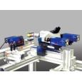
北京欧兰科技发展有限公司为您提供《溶液,流体中速度场,速度矢量场,显微速度矢量场检测方案(粒子图像测速)》,该方案主要用于其他中速度场,速度矢量场,显微速度矢量场检测,参考标准--,《溶液,流体中速度场,速度矢量场,显微速度矢量场检测方案(粒子图像测速)》用到的仪器有显微粒子成像测速系统(Micro PIV)
推荐专场


相关方案
更多
该厂商其他方案
更多