


This study reports on the breaking up of droplets which can be manipulated with acoustic fields. The
oscillation of vortex in a breaking droplet is observed. The droplet size is dependent on the flow-rate
combination of the two fluids as well as the frequency and power of the acoustic actuation. Acoustic
microstreaming flow is observed in the dispersed phase at the cross-junction of the device. The
microstreaming flow causes a stratified vortex flow structure within the dispersed phase. Two
stratified vortex centers at the side poles of the droplet are found.
方案详情

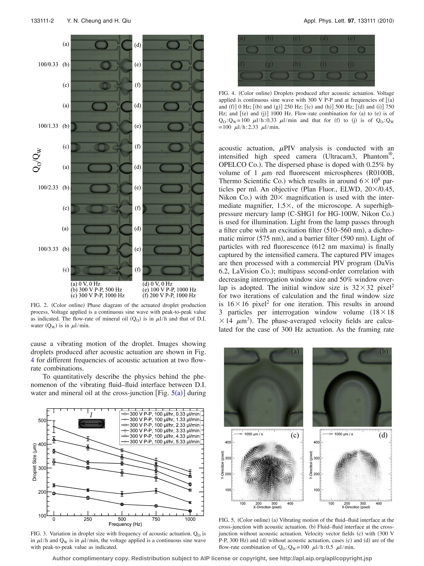
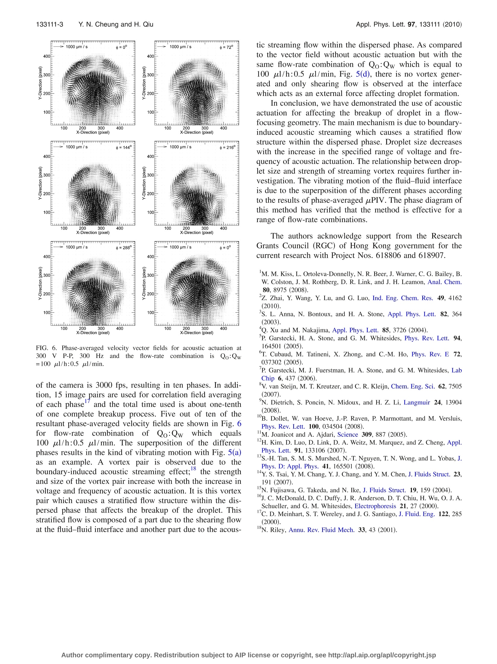
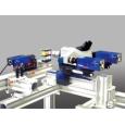
APPLIED PHYSICS LETTERS 97, 133111 (2010) 133111-2 Y.N. Cheung and H. QiuAppl. Phys. Lett. 97,133111(2010) Acoustic microstreaming for droplet breakup in a microflow-focusingdevice Yin Nee Cheung and Huihe Qiu Department of Mechanical Engineering, The Hong Kong University of Science and Technology,Clear Water Bay, Kowloon, Hong Kong (Received 27 June 2010; accepted 31 August 2010; published online 29 September 2010) This study reports on the breaking up of droplets which can be manipulated with acoustic fields. Theoscillation of vortex in a breaking droplet is observed. The droplet size is dependent on the flow-ratecombination of the two fluids as well as the frequency and power of the acoustic actuation. Acousticmicrostreaming flow is observed in the dispersed phase at the cross-junction of the device. Themicrostreaming flow causes a stratified vortex flow structure within the dispersed phase. Twostratified vortex centers at the side poles of the droplet are found. C 2010 American Institute ofPhysics. [doi:10.1063/1.34959866] Single and double emulsion production technologieshave wide applications in bioengineering and food process-ing; for example, the use of a high-throughput microfluidicchip for polymerase chain reaction in picoliter droplets forthe detectionnandquantification of rarespeciesin apopulation and the use of silica spheres with a large poresize for fast adsorption of proteins. Microfluidic devices,flow-focusing, and T-junctions with different geometries areapplied to the production of single emulsions with differentsizes.1 Experimental investigations show that the size ofdroplets produced by both methods mainly depend on theflow-rate ratios between the inner and the outer fluids witha specific pair of fluidsand device geometries underinvestigation.3 Other parameters which would also affectthe size of the produced droplet include the junction angle ofthe device, surface tension, viscosity of the fluids, etc. Inorder to increase the range of droplet size which is onlycontrolled by the flow-rate ratios between the two fluids inmost devices, it is suggested that actuators or other meansshould be integrated with the device so as to achieve localcontrol of the droplet breakup. Attempts to provide localcontrol have been made by Kim et al.and Tan et al.Butlocal control by an electric field as suggested by Kim et al. isonly applicable for small flow-rate ratios (flow-rate of theinner fluid to outer fluid) with a low flow-rate of the dis-persed phase. In the present study, we demonstrate the inte-gration of a piezoelectric actuator with a microfluidic flow-focusing device so as to achieve local control of dropletproduction. Acoustic streaming flow is observed within thedispersed phase and phase-averaged microparticle-image-velocimetry (uPIV) (Refs. 14 and 15) is applied for quanti-tative verification of the flow field at different phases withinthe dispersed phase. Soft-lithography is adopted for the fabrication of theflow-focusing device (Fig. 1SII-).16 SU-8 (SU-8 2035, Micro-Chem Co.) is spin-coated with a thickness of about 100 umand is exposed to UV light and developed to give a rectan-gular microchannel pattern. The stamp resin used to replicatethe microchannel is the 10:1 mixture of polydimethylsilox-ane (PDMS, SYLGARD 184, Dow Corning Co.) and itscuring agent which is degassed in a vacuum chamber before use. The hardened PDMS with punched holes is then bondedto a glass wafer by oxygen plasma bonding. De-ionized (D.I.) water is used as the dispersed phaseand mineral oil (M5904, SIGMA-ALDRICH) is used as thecontinuous phase. The flow-rates of the two fluids are con-trolled by a twin syringe pump (Model 33, Harvard Appara-tus Co.). Acoustic actuation is provided by a piezoelectricactuator attached onto the top of the PDMS device next tothe cross-junction [Fig. 1(b)]. The thickness of the PDMS atthe location of the piezoelectric actuator attachment is re-duced to 0.6 mm for efficient acoustic actuation. The actua-tion signal is a continuous sine wave which is output from afunction generator (HP33120A, Hewlett-Packard Co.) andthen amplified by a high speed bipolar amplifier (BA4825,NF Co.). A high speed camera (MotionXtra HG-100K, RedlakeCo.) is used for capturing the actuated droplet productionprocess. The camera is attached to a microscope (EclipseTE2000-U, Nikon Co.) and the microfluidic device is placedon top of it for observation. A continuous reduction in drop-let size with increase in frequency and voltage is shown inFig. 2 at different flow-rate combinations. A vibrating fluid-fluid interface is clearly seen in cases (b), (c), and (f), and thereduction in droplet size increases with increase in the extentof vibrating motion. The variation in the droplet size,I [Fig.3], with frequency of actuation is measured and the result isshown in Fig. 3. A decreasing trend of the droplet size isindicated in this figure with a larger reduction in droplet sizeat higher water flow-rates. Droplet size is measured at a lo-cation where the effect of the acoustic actuation does not FIG. 1. (Color online) (a) Flow-focusing device geometry. Lw=Lo=L≈150 umand L40 um. (b)Piezoelectric actuator attached onto the topof the flow-focusing device. FIG. 2. (Color online) Phase diagram of the actuated droplet productionprocess. Voltage applied is a continuous sine wave with peak-to-peak valueas indicated. The flow-rate of mineral oil (Qo) is in ul/h and that of D.I.water (Qw) is in ul/min. cause a vibrating motion of the droplet. Images showingdroplets produced after acoustic actuation are shown in Fig.4 for different frequencies of acoustic actuation at two flow-rate combinations. To quantitatively describe the physics behind the phe-nomenon of the vibrating fluid-fluid interface between D.I.water and mineral oil at the cross-junction [Fig. 5(a)] during FIG. 3. Variation in droplet size with frequency of acoustic actuation. Qo isin ul/h and Qw is in ul/min, the voltage applied is a continuous sine wavewith peak-to-peak value as indicated. FIG. 4. (Color online) Droplets produced after acoustic actuation. Voltageapplied is continuous sine wave with 300 V P-P and at frequencies of [(a)and (f)] 0 Hz; [(b) and (g)] 250 Hz;[(c) and (h)] 500 Hz; [(d) and (i)] 750Hz; and [(e) and (j)] 1000 Hz. Flow-rate combination for (a) to (e) is ofQo:Qw=100 ul/h:0.33 ul/min and that for (f) to (j) is of Qo:Qw=100 pl/h:2.33 ul/min. acoustic actuation, uPIV analysis is conducted withanintensified high speed camera.((Ultracam3, Phantom@,OPELCO Co.). The dispersed phase is doped with 0.25% byvolume of 1 um red fluorescent microspheres (R0100B,Thermo Scientific Co.) which results in around 6×10° par-ticles per ml. An objective (Plan Fluor., ELWD, 20×/0.45,Nikon Co.) with 20× magnification is used with the inter-mediate magnifier, 1.5×, of the microscope. A superhigh-pressure mercury lamp (C-SHG1 for HG-100W, Nikon Co.)is used for illumination. Light from the lamp passes througha filter cube with an excitation filter (510-560 nm), a dichro-matic mirror (575 nm), and a barrier filter (590 nm). Light ofparticles with red fluorescence (612 nm maxima) is finallycaptured by the intensified camera. The captured PIV imagesare then processed with a commercial PIV program (DaVis6.2, LaVision Co.); multipass second-order correlation withdecreasing interrogation window size and 50% window over-lap is adopted. The initial window size is 32×32 pixelfor two iterations of calculation and the final window sizeis 16×16 pixel’ for one iteration. This results in around3particless per interrogation window volume (18×18×14 um’). The phase-averaged velocity fields are calcu-lated for the case of 300 Hz actuation. As the framing rate FIG. 5. (Color online) (a) Vibrating motion of the fluid-fluid interface at thecross-junction with acoustic actuation. (b) Fluid-fluid interface at the cross-junction without acoustic actuation. Velocity vector fields (c) with (300 VP-P, 300 Hz) and (d) without acoustic actuation, cases (c) and (d) are of theflow-rate combination of Qo:Qw=100 ul/h:0.5 ul/min. FIG. 6. Phase-averaged velocity vector fields for acoustic actuation at300) VP-P, 3000HzZ2and1tthe fflow-rate combinationisisQo:Qw=100 ul/h:0.5 ul/min. of the camera is 3000 fps, resulting in ten phases. In addi-tion, 15 image pairs are used for correlation field averagingof each phase and the total time used is about one-tenthof one complete breakup process. Five out of ten of theresultant phase-averaged velocity fields are shown in Fig. 6forflow-rateecombinationofQo:Qw which1equals100 ul/h:0.5 ul/min. The superposition of the differentphases results in the kind of vibrating motion with Fig. 5(a)as an example. A vortex pair is observeddue to theboundary-induced acoustic streaming effect; the strengthand size of the vortex pair increase with both the increase involtage and frequency of acoustic actuation. It is this vortexpair which causes a stratified flow structure within the dis-persed phase that affects the breakup of the droplet. Thisstratified flow is composed of a part due to the shearing flowat the fluid-fluid interface and another part due to the acous- tic streaming flow within the dispersed phase. As comparedto the vector field without acoustic actuation but with thesame flow-rate combination of Qo:Qw which is equal to100 ul/h:0.5 ul/min, Fig. 5(d), there is no vortex gener-ated and only shearing flow is observed at the interfacewhich acts as an external force affecting droplet formation. In conclusion, we have demonstrated the use of acousticactuation for affecting the breakup of droplet in a flow-focusing geometry. The main mechanism is due to boundary-induced acoustic streaming which causes a stratified flowstructure within the dispersed phase. Droplet size decreaseswith the increase in the specified range of voltage and fre-quency of acoustic actuation. The relationship between drop-let size and strength of streaming vortex requires further in-vestigation. The vibrating motion of the fluid-fluid interfaceis due to the superposition of the different phases accordingto the results of phase-averaged uPIV. The phase diagram ofthis method has verified that the method is effective for arange of flow-rate combinations. The authors acknowledge support from the ResearchGrants Council (RGC) of Hong Kong government for thecurrent research with Project Nos. 618806 and 618907. M. M. Kiss, L. Ortoleva-Donnelly, N. R. Beer, J. Warner, C. G. Bailey, B.W. Colston, J. M. Rothberg, D. R. Link, and J. H. Leamon, Anal. Chem.80,8975 (2008). Z. Zhai, Y. Wang, Y. Lu, and G. Luo, Ind. Eng. Chem. Res. 49, 4162(2010). S. L. Anna, N. Bontoux, and H. A. Stone, Appl. Phys. Lett. 82, 364(2003). “Q. Xu and M. Nakajima, Appl. Phys. Lett. 85,3726 (2004). ( P . G arstecki, H. A . S tone, a nd G. M . Wh i tesides, Ph y s. R e v . Le t t. 9 4 , 164501 ( 2005). ) T. Cubaud, M. Tatineni, X. Zhong, and C.-M. Ho, Phys. Rev. E 72,037302 (2005). P. Garstecki, M. J. Fuerstman, H. A. Stone, and G. M. Whitesides, LabChip 6, 437 (2006). °V. van Steijn, M. T. Kreutzer, and C. R. Kleijn, Chem. Eng. Sci. 62, 7505(2007). N. Dietrich, S. Poncin, N. Midoux, and H. Z. Li, Langmuir 24, 13904(2008). B. Dollet, W. van Hoeve, J.-P. Raven, P. Marmottant, and M. Versluis,Phys. Rev. Lett. 100, 034504 (2008). M. Joanicot and A. Ajdari, Science 309,887 (2005). H. Kim, D. Luo, D. Link, D. A. Weitz, M. Marquez, and Z. Cheng,Appl.Phys. Lett. 91, 133106 (2007). 1S.-H. Tan, S. M. S. Murshed,N.-T. Nguyen, T. N. Wong, and L. Yobas,J.Phys. D: Appl. Phys. 41, 165501 (2008). 14yY.S. Tsai, Y. M. Chang, Y. J. Chang, and Y. M. Chen,J. Fluids Struct. 23,191 (2007). N. Fujisawa, G. Takeda, and N. Ike, J. Fluids Struct. 19, 159 (2004). J. C. McDonald, D. C. Duffy, J. R. Anderson, D. T. Chiu, H. Wu, O. J. A.Schueller, and G. M. Whitesides, Electrophoresis 21, 27 (2000). C. D. Meinhart, S. T. Wereley, and J. G. Santiago,J. Fluid. Eng. 122, 285(2000). ( N. R i ley, A nnu. R e v. F l uid M e ch. 3 3 , 43 (2 0 01). ) Electronic mail: meqiu@ust.hk./$ American Institute of PhysicsAuthor complimentary copy. Redistribution subject to AIP license or copyright, see http://apl.aip.org/apl/copyright.jsp
确定
还剩1页未读,是否继续阅读?

产品配置单
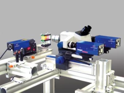
北京欧兰科技发展有限公司为您提供《微流体,聚集装置中液滴破裂,声致微流化,流场,速度场,速度矢量场,PIV,粒子成像测速检测方案(粒子图像测速)》,该方案主要用于其他中液滴破裂,声致微流化,流场,速度场,速度矢量场,PIV,粒子成像测速检测,参考标准--,《微流体,聚集装置中液滴破裂,声致微流化,流场,速度场,速度矢量场,PIV,粒子成像测速检测方案(粒子图像测速)》用到的仪器有显微粒子成像测速系统(Micro PIV)
推荐专场


相关方案
更多
该厂商其他方案
更多