
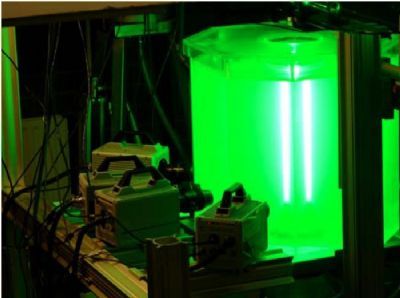


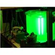
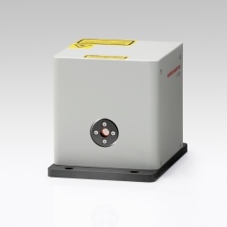
采用立陶宛Ekspla公司的PL2231C-20, 20 Hz, 80 ps,532 nm, >15 mJ/pulse 激光器做光源,采用LaVision公司的sCMOS (2560 x 2160 pixels, 6.5 gm pixel pitch,16-bit depth) 相机。采用四波混频,相位共轭镜补偿等技术实现消除激波密度不均匀性干扰的相干成像。
方案详情

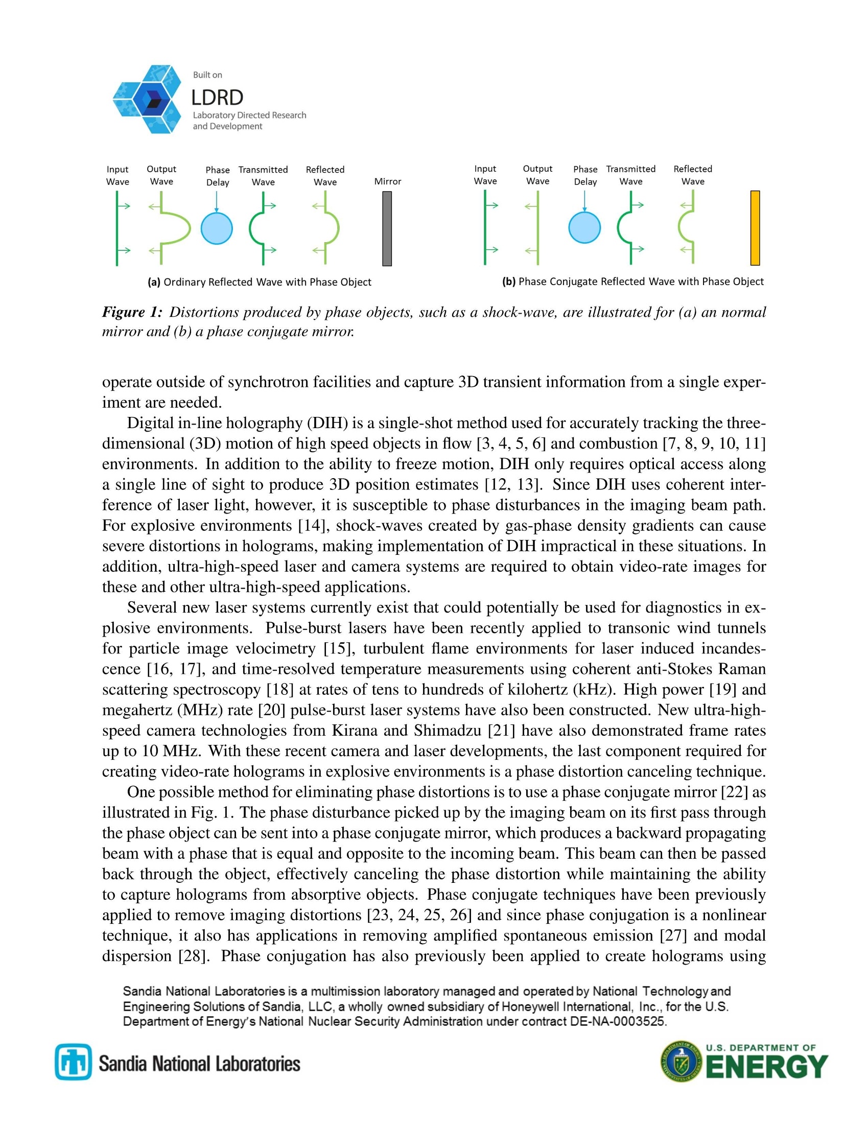
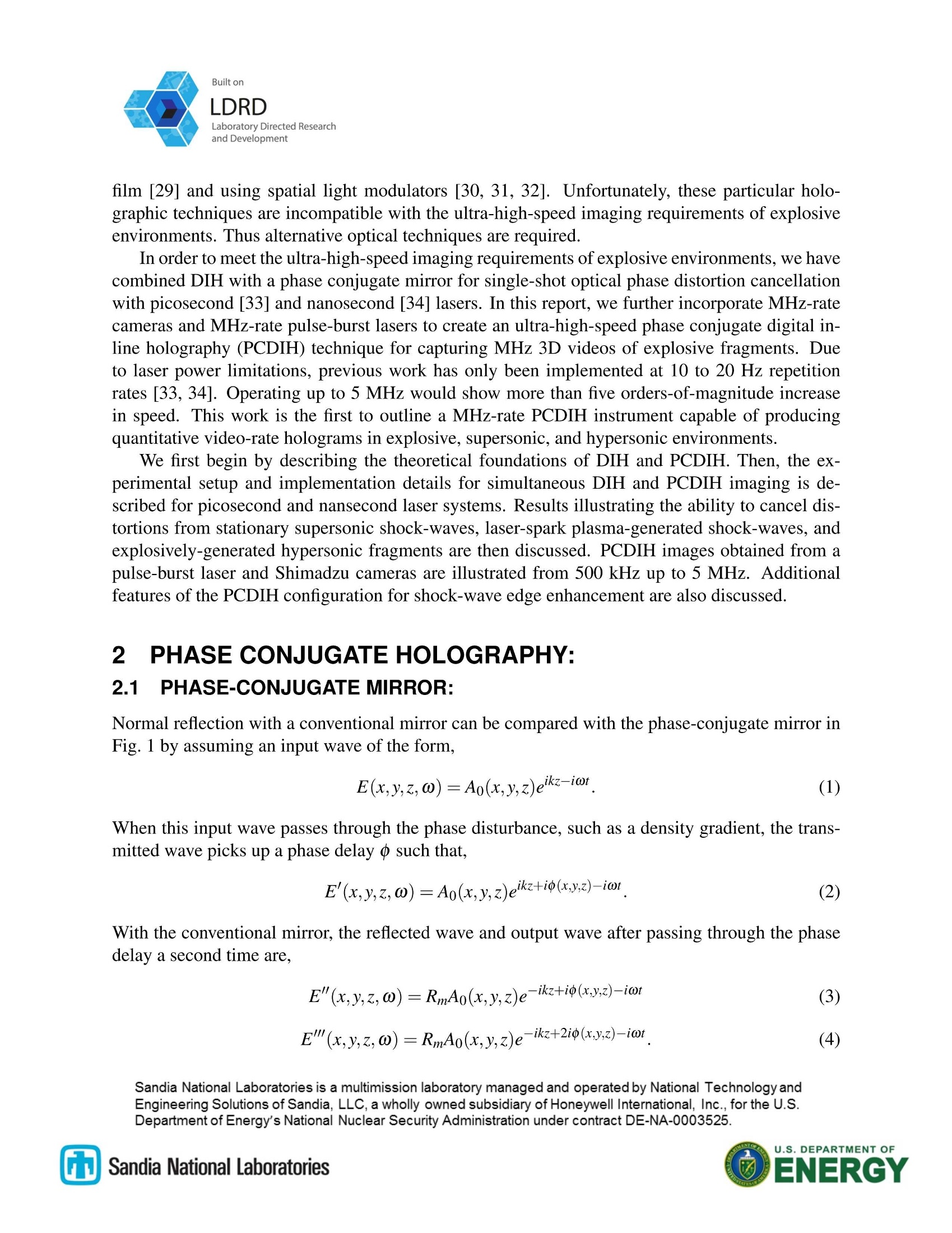
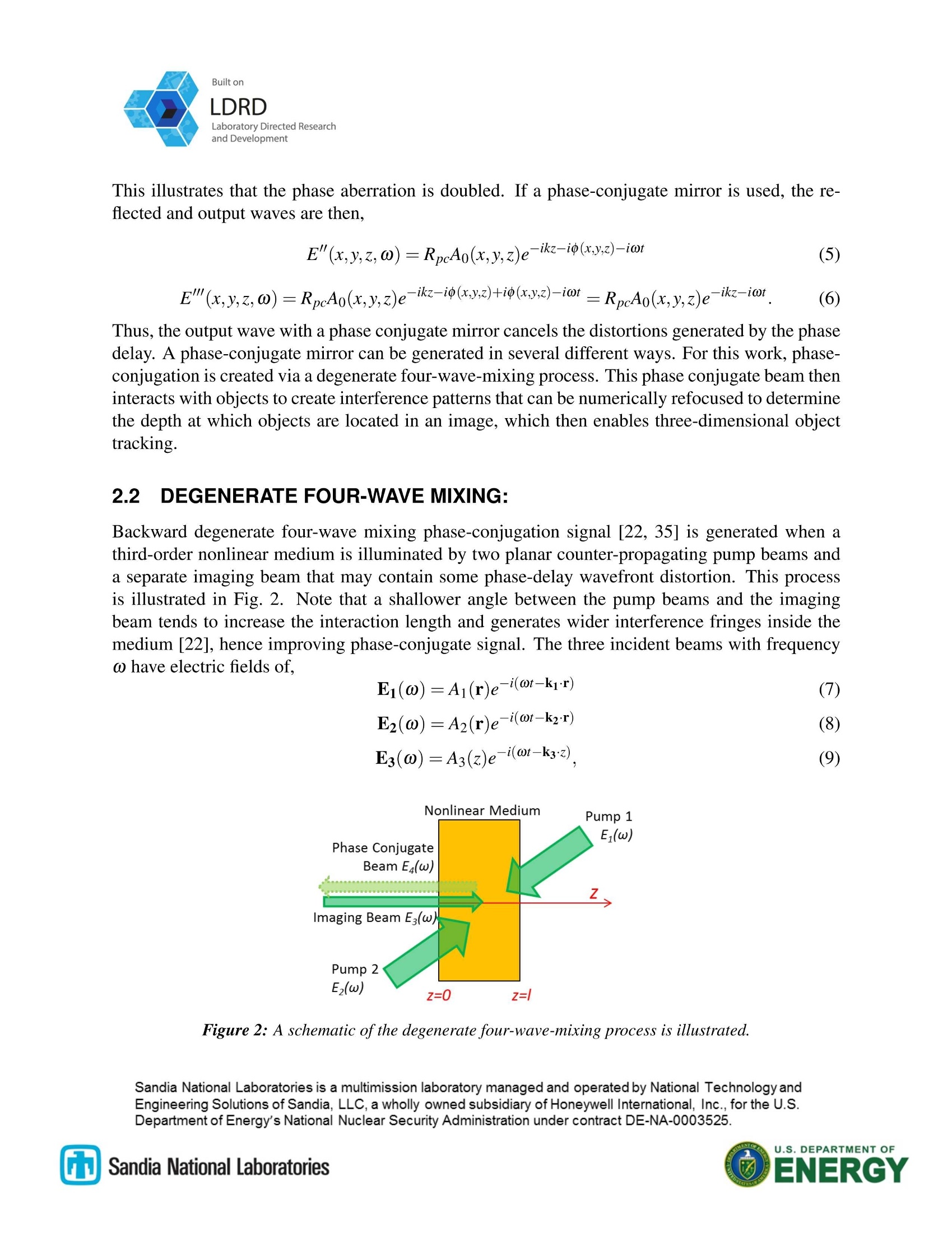
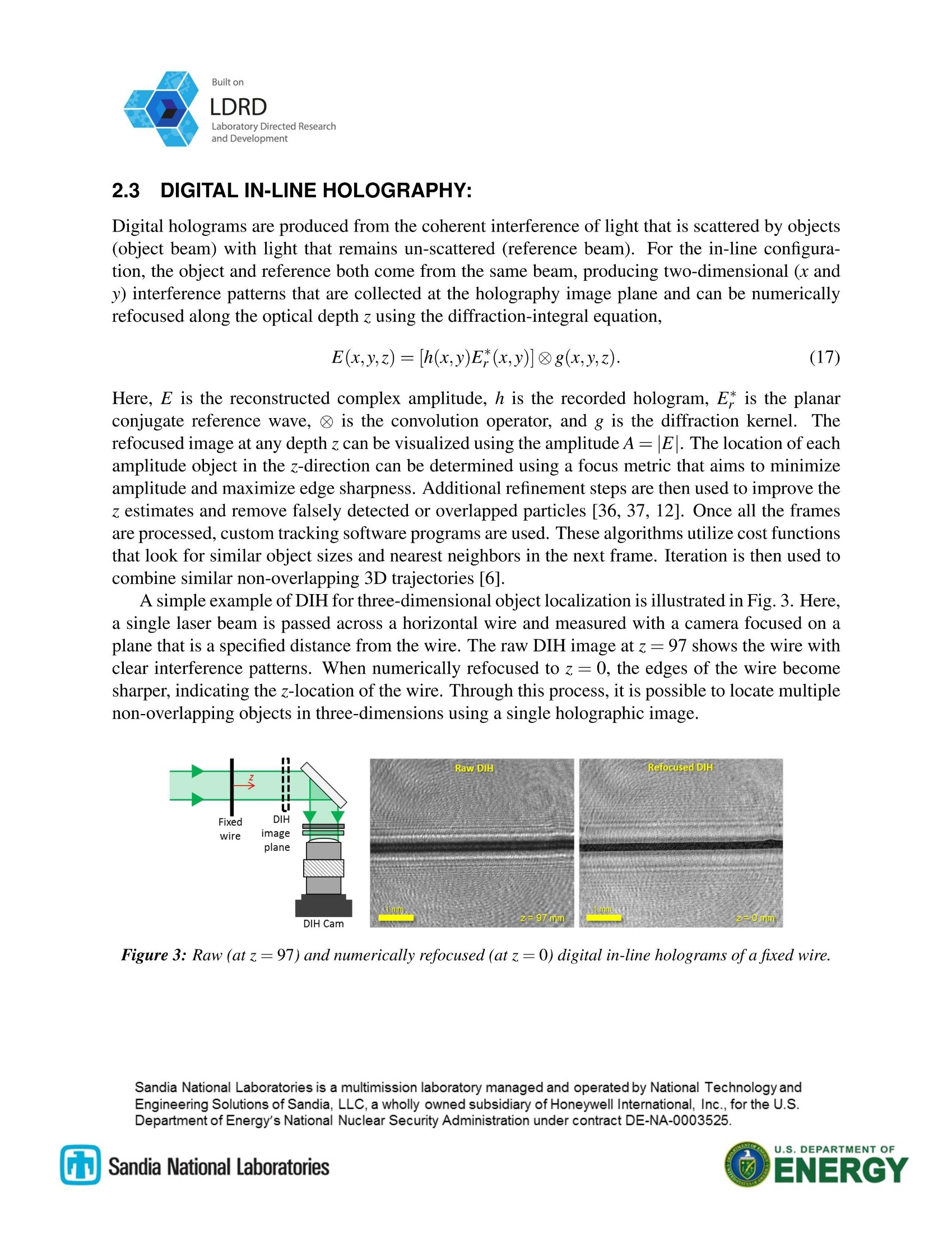
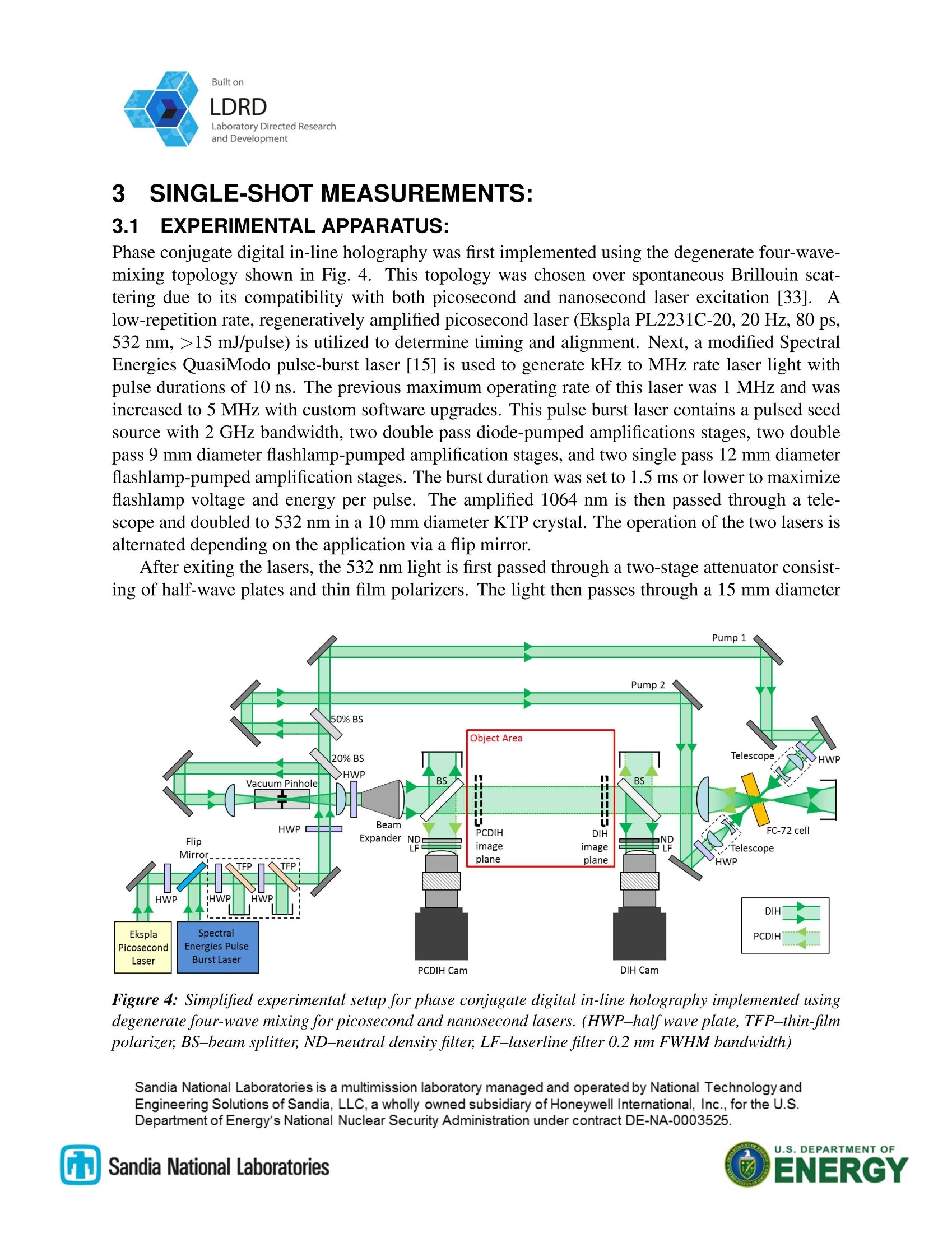
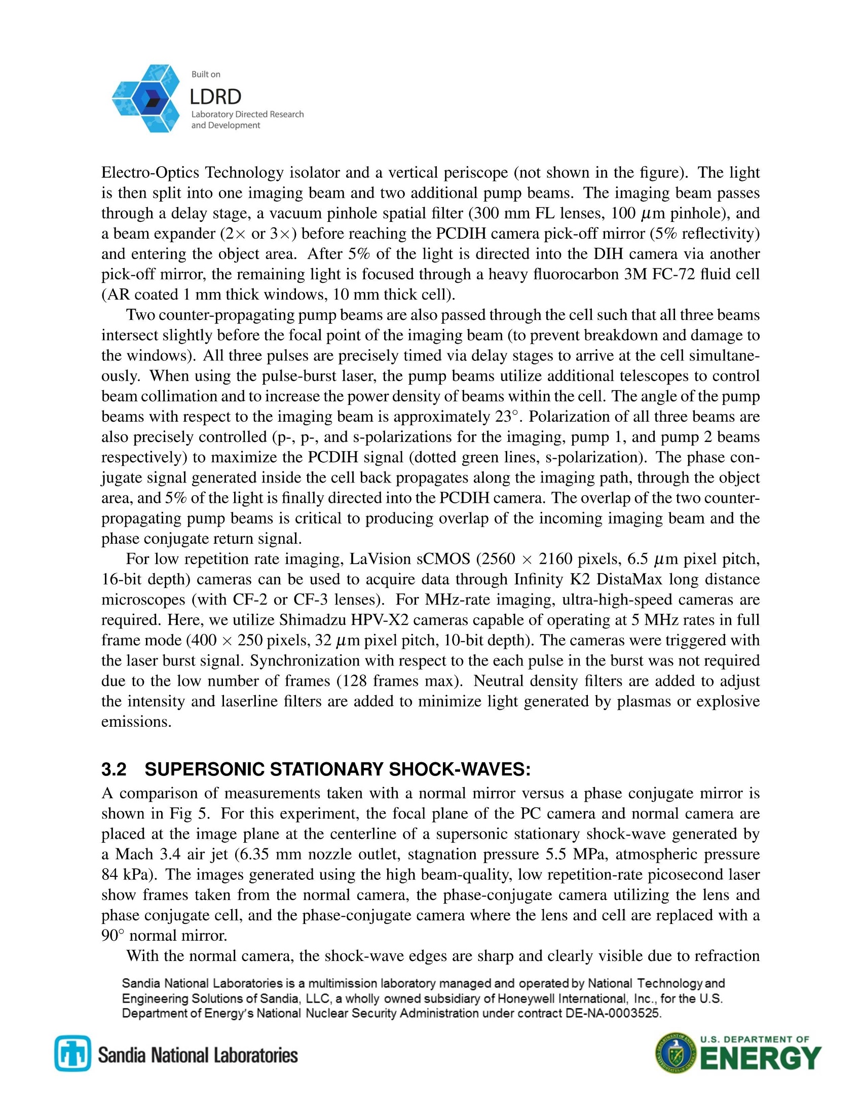
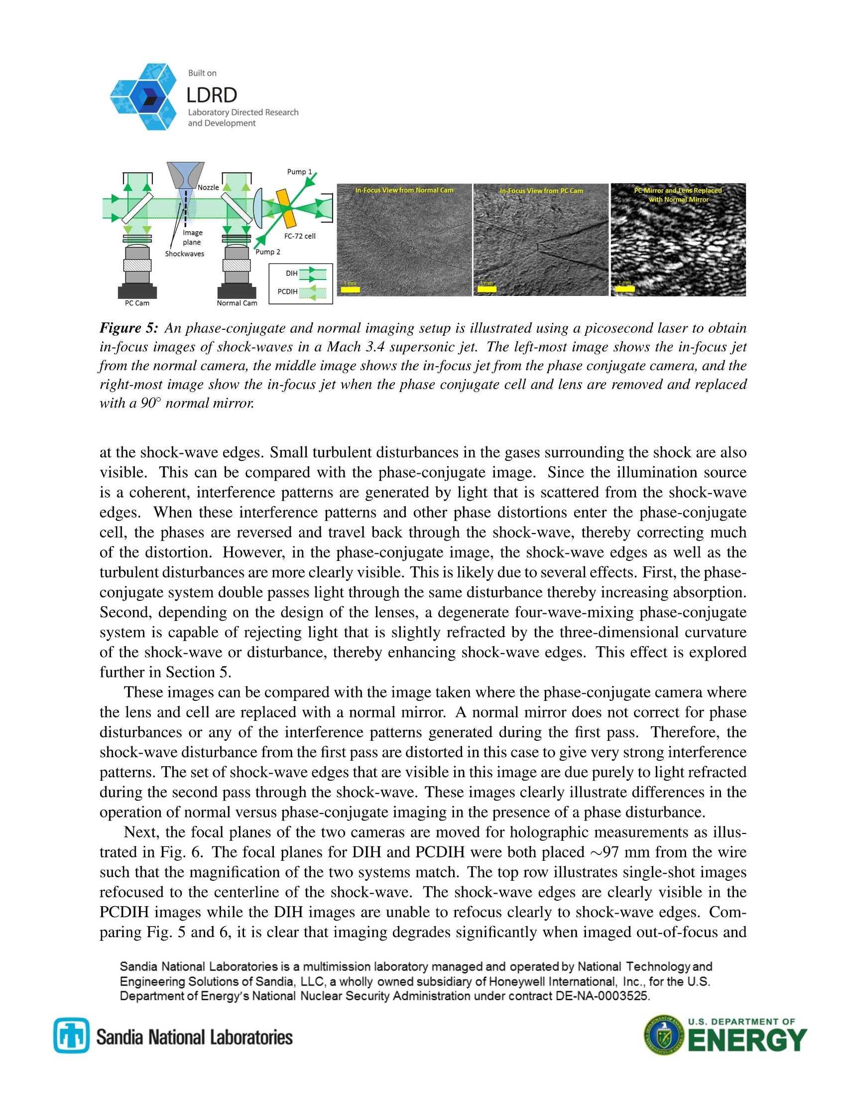
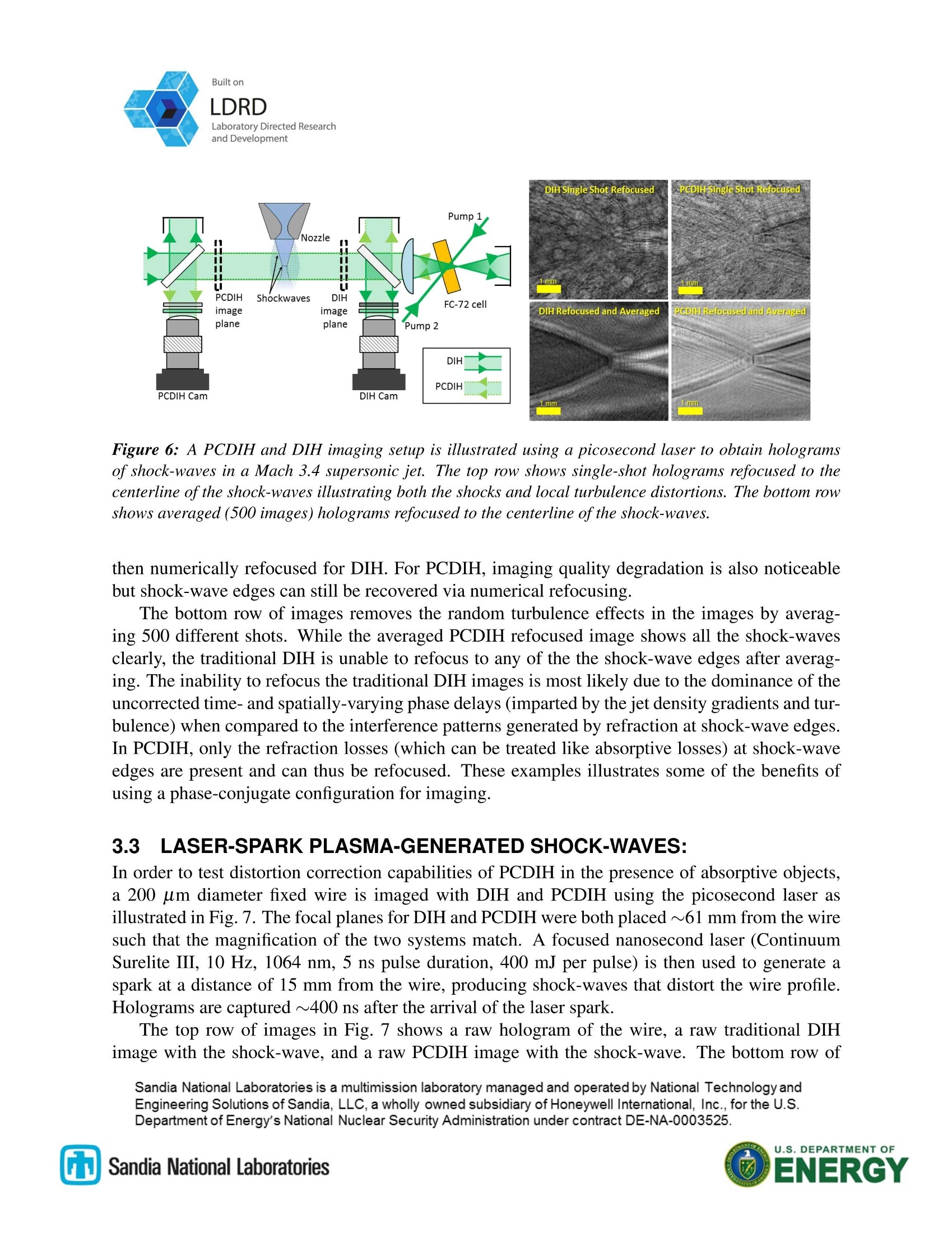
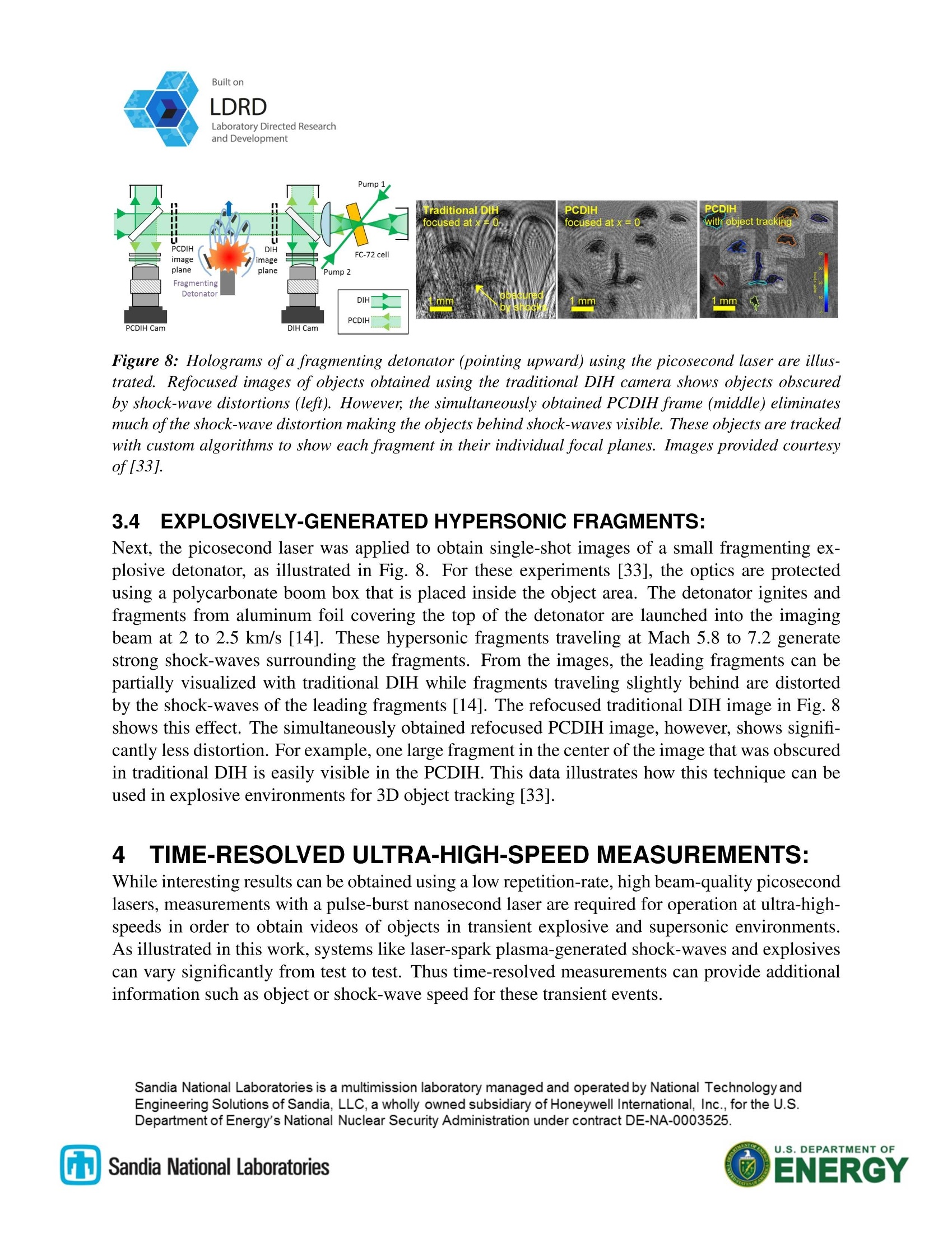
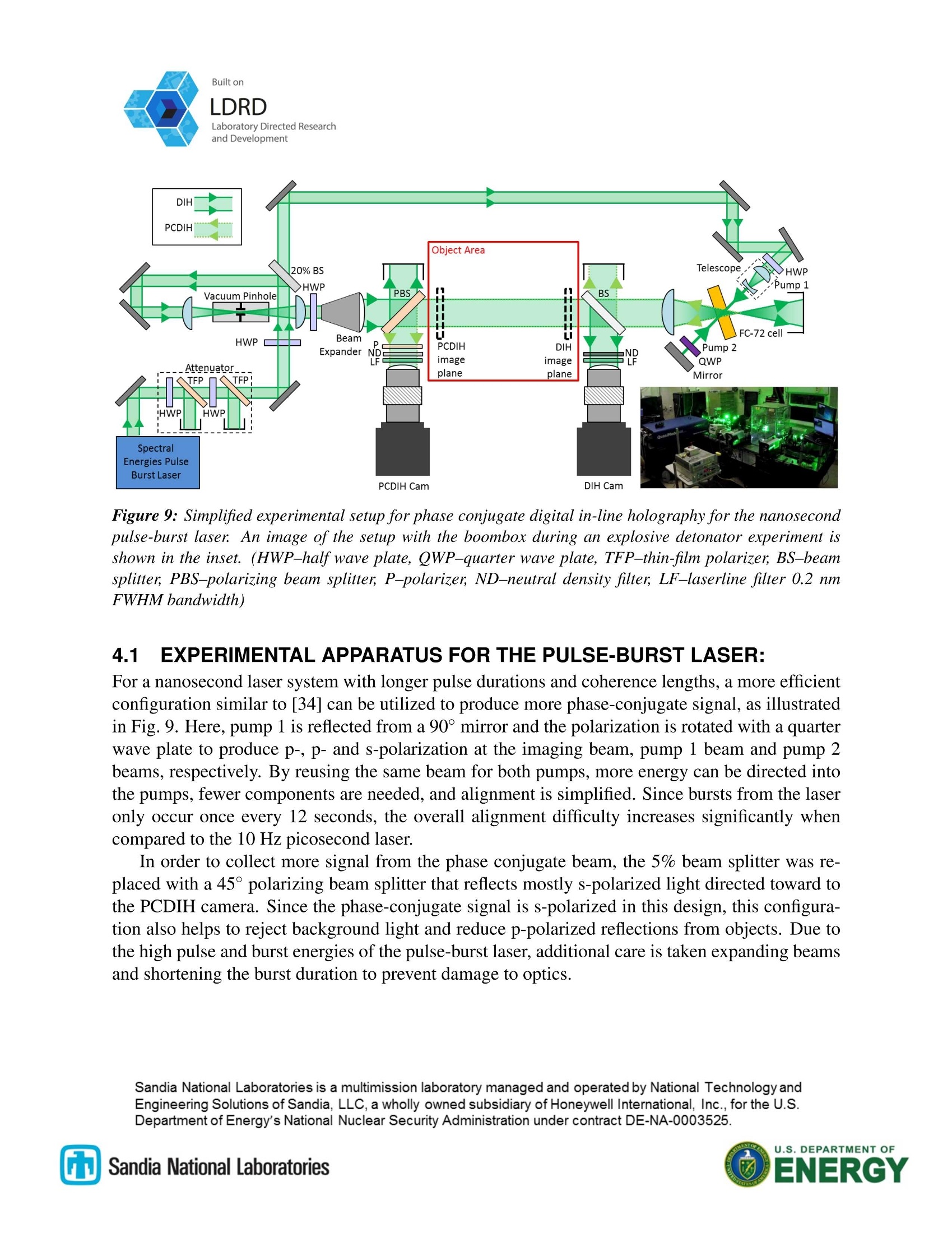
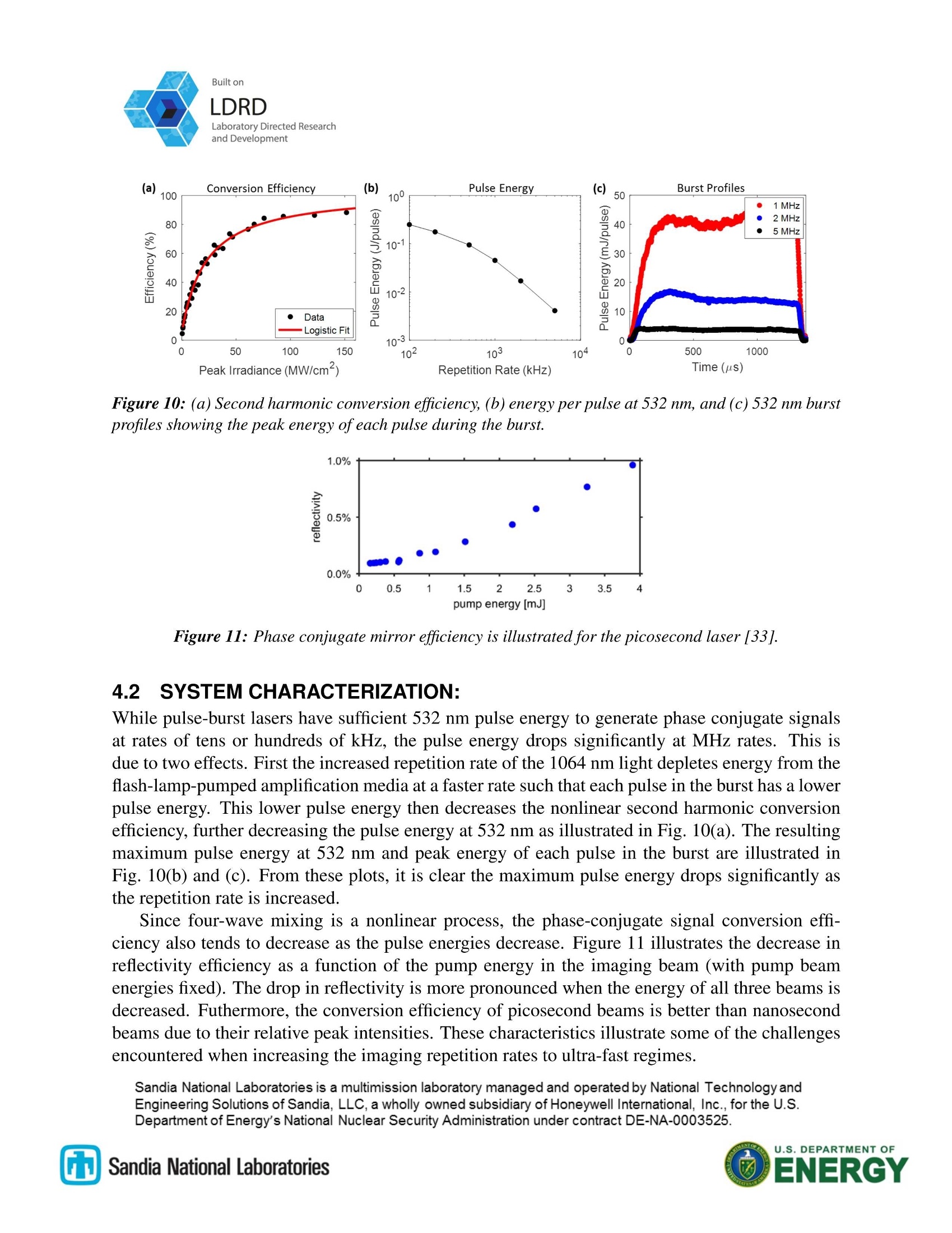
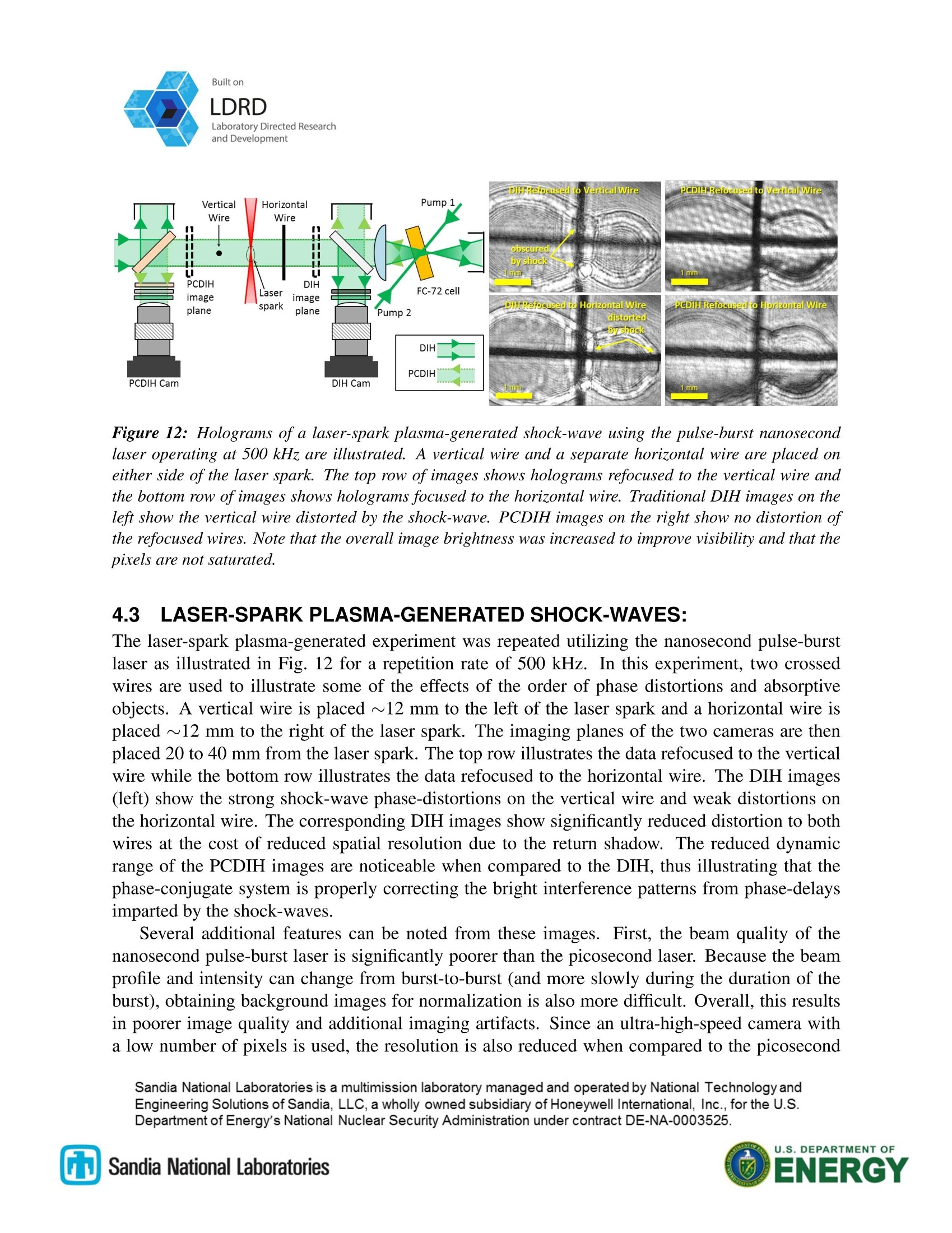
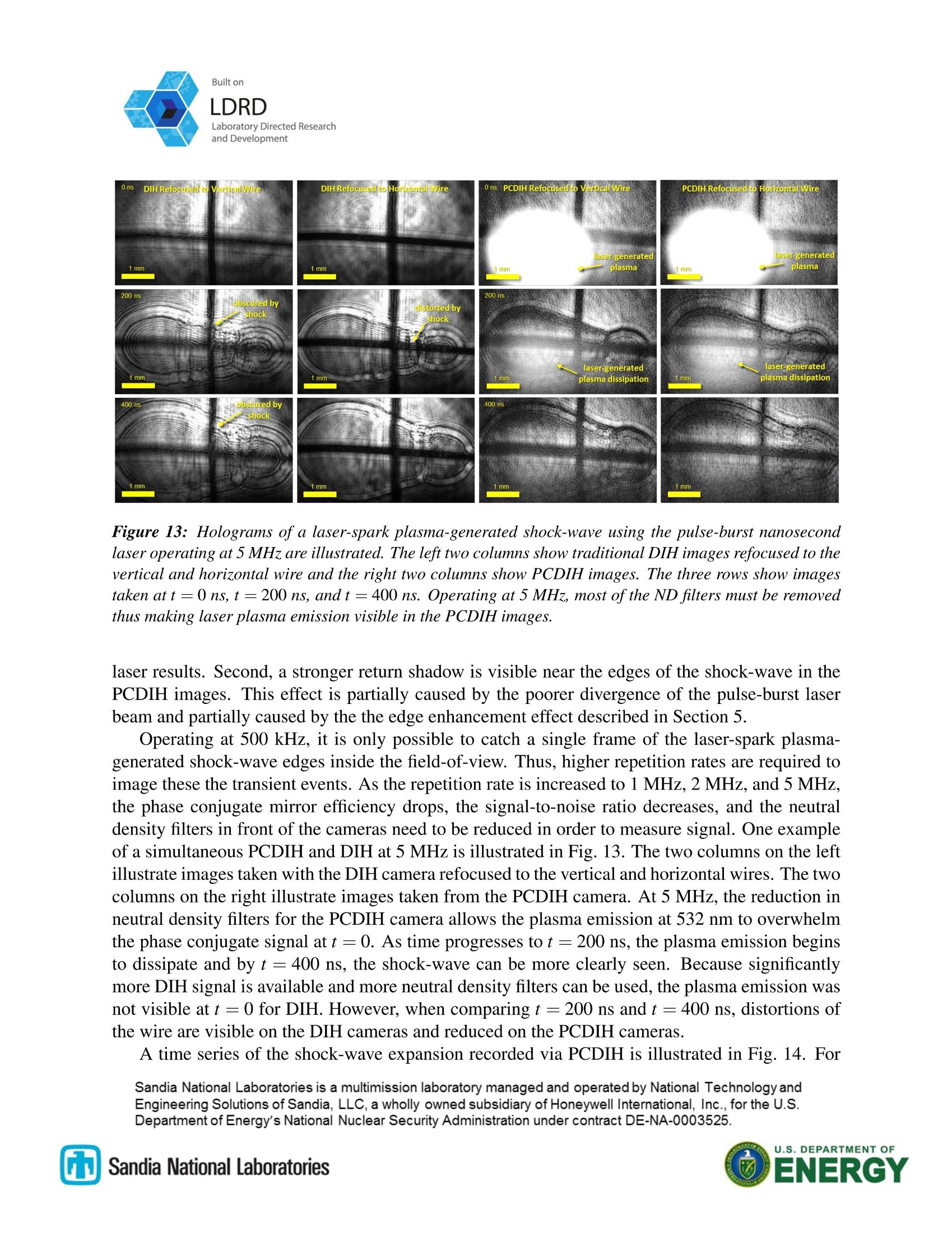
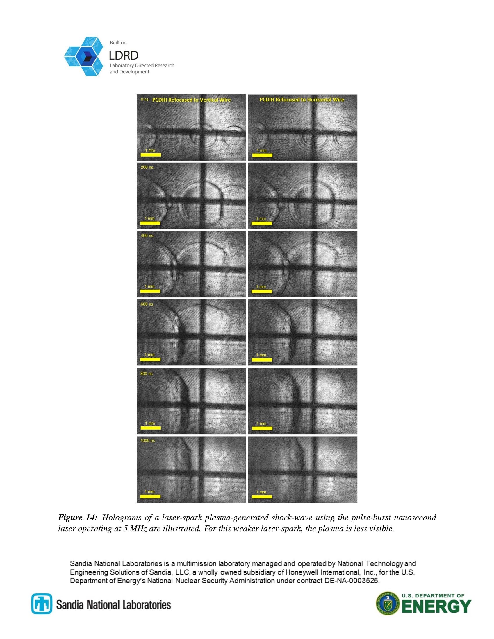
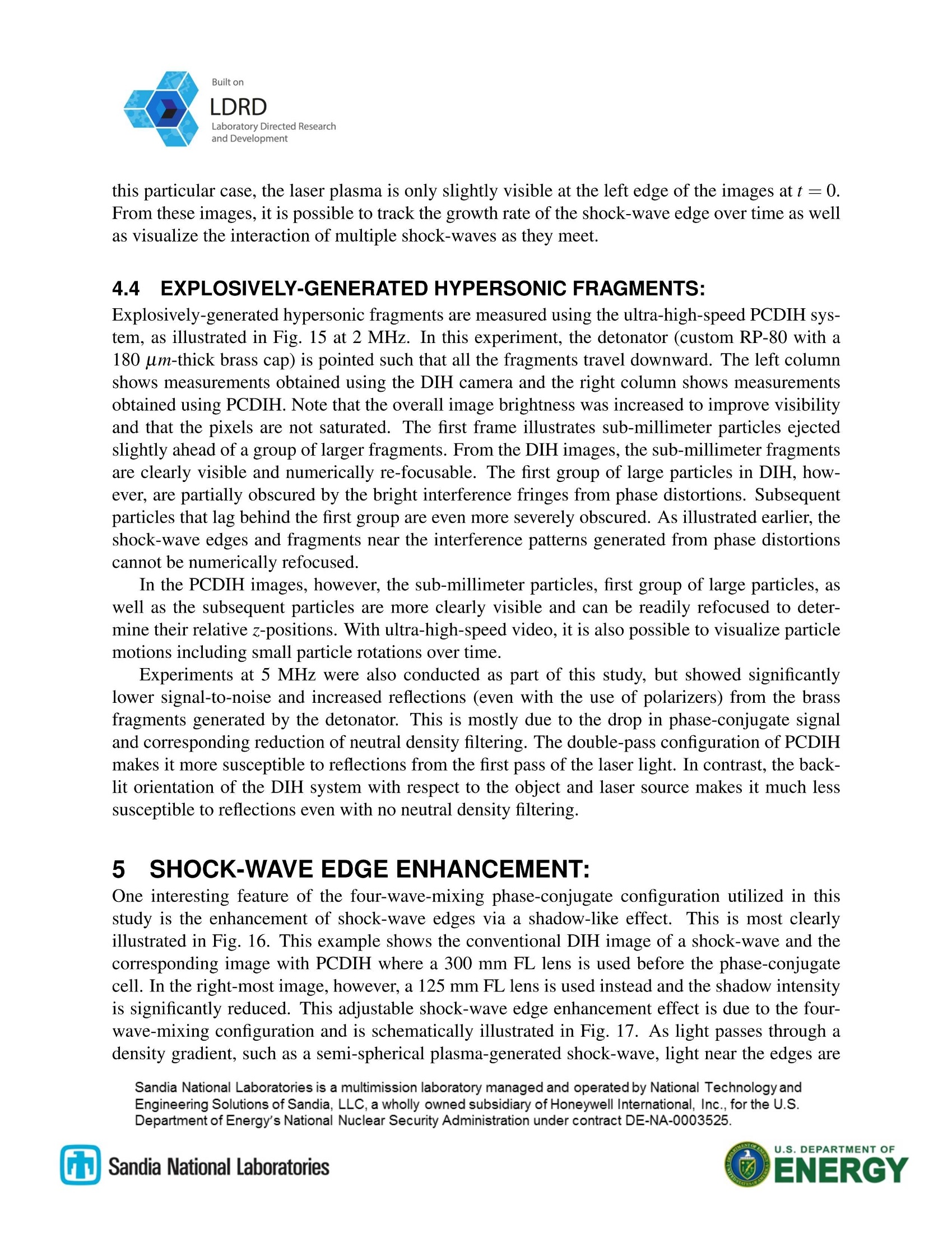
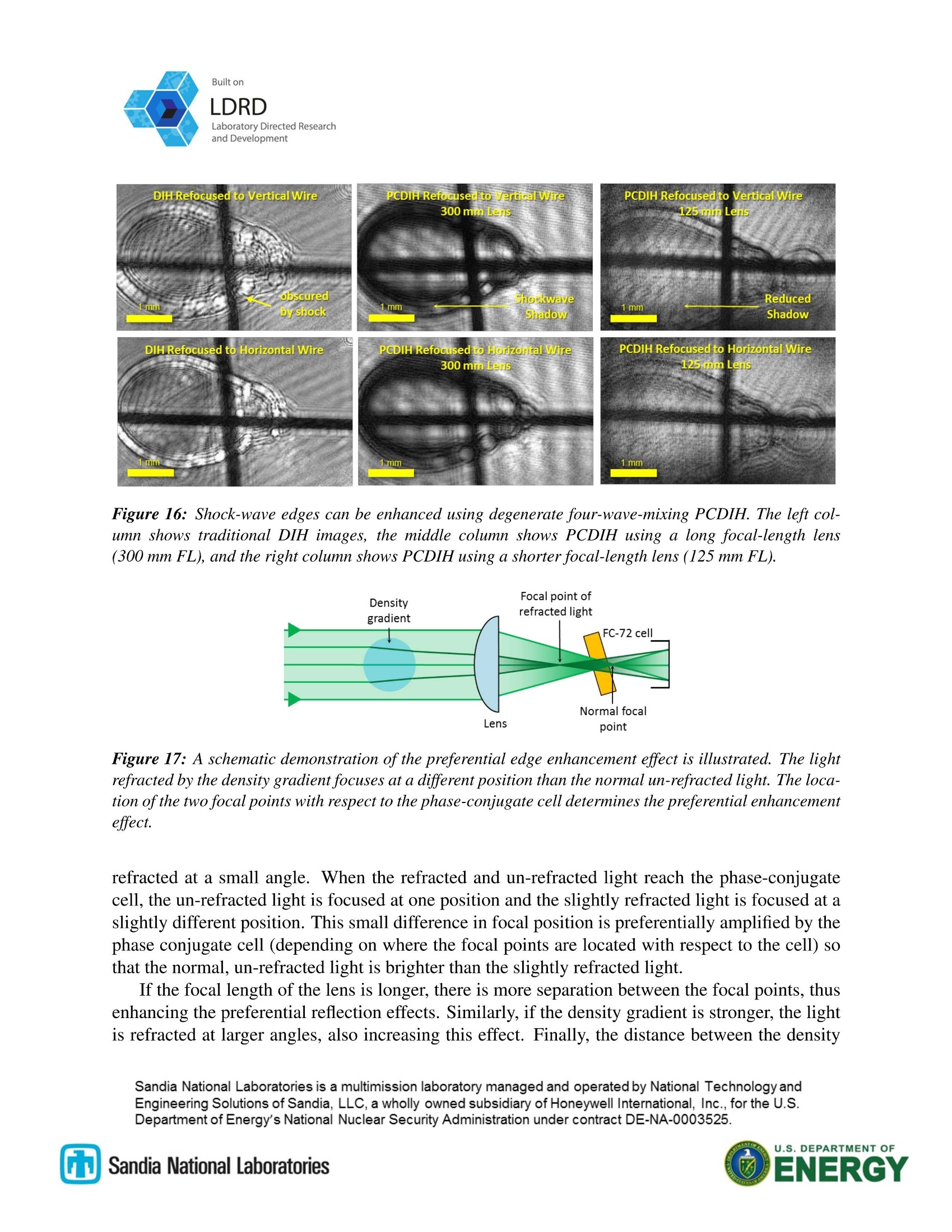
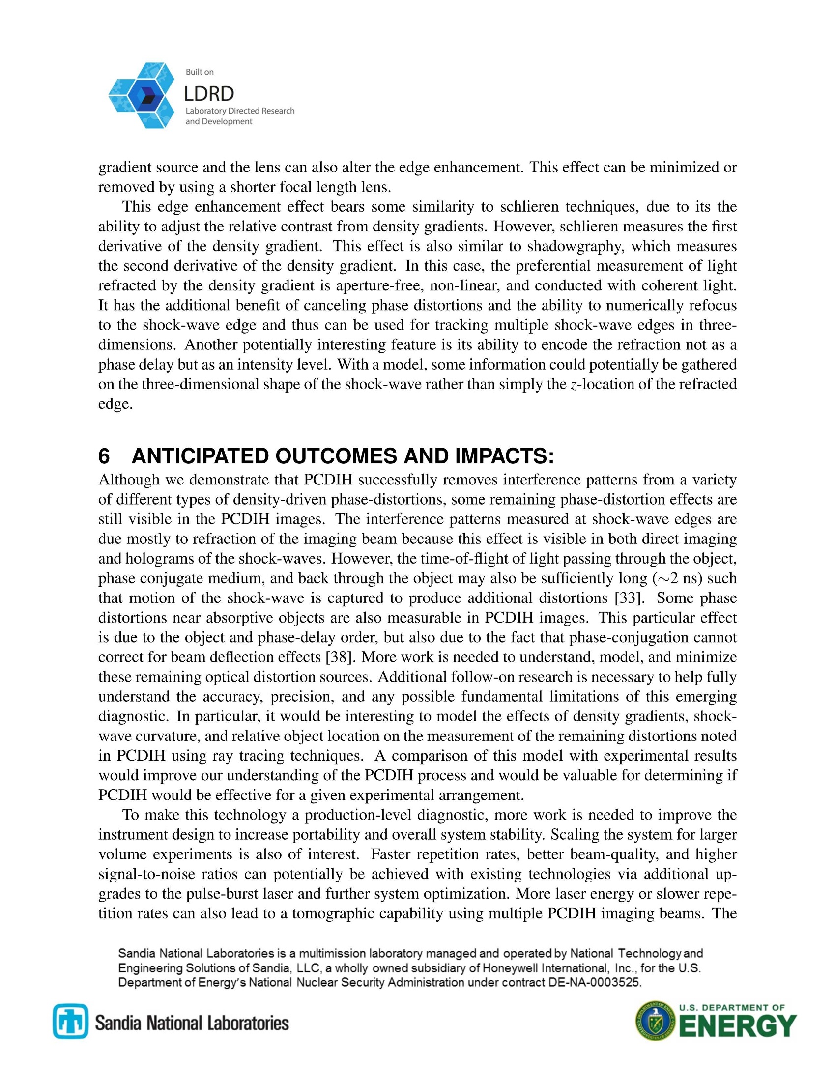
SAND2018-10598RBuilt onLDRDLaboratory Directed Researchand Development SAND2018-XXXXRLDRD PROJECT NUMBER:211659 LDRD PROJECT TITLE:Three-Dimensional Imaging through Shock- Waves at Ultra-High Speed PROJECT TEAM MEMBERS:Yi Chen Mazumdar, Michael E. Smyser,Jeffery D. Heyborne, and Daniel R. Guildenbecher ABSTRACT: Imaging diagnostics that utilize coherent light, such as digital in-line holography, are important forobject sizing and tracking applications. However, in explosive, supersonic, or hypersonic environ-ments, gas-phase shocks impart imaging distortions that obscure internal objects. To circumventthis problem, some research groups have conducted experiments in vacuum, which inherentlyalters the physical behavior. Other groups have utilized single-shot flash x-ray or high-speed syn-chrotron x-ray sources to image through shock-waves. In this work, we combine digital in-lineholography with a phase conjugate mirror to reduce the phase distortions caused by shock-waves.The technique operates by first passing coherent light through the shock-wave phase-distortionand then a phase-conjugate mirror. The phase-conjugate mirror is generated by a four-wave mix-ing process to produce a return beam that has the exact opposite phase-delay as the forward beam.Therefore, by passing the return beam back through the phase-distortion, the phase delays pickedup during the initial pass are canceled, thereby producing improved coherent imaging. In thiswork, we implement phase conjugate digital in-line holography (PCDIH) for the first time with ananosecond pulse-burst laser and ultra-high-speed cameras. This technique enables accurate mea-surement of the three-dimensional position and velocity of objects through shock-wave distortionsat video rates up to 5 MHz. This technology is applied to improve three-dimensional imaging in avariety of environments from imaging supersonic shock-waves through turbulence, sizing objectsthrough laser-spark plasma-generated shock-waves, and tracking explosively generated hypersonicfragments. Theoretical foundations and additional capabilities of this technique are also discussed. 1 INTRODUCTION: Many environments from hypersonics to explosives, create imaging challenges plagued by opticaldistortions due to shock-waves. Current state-of-the-art experiments conducted by Los Alamosand Argonne use synchrotron x-rays [1] to overcome shock-waves while capturing a maximum offour images per experiment at 6.7 million frames-per-second [2]. To construct three-dimensionalpictures, multiple repetitions with different views are required [2]. Ultimately, diagnostics that ( Sandia National Laboratories is a multimission laboratory managed and operated by National Te c hnology andEngineering S o lutions of S a ndia, LLC, a w h o lly ow n ed subsidiary of Honeywell International, Inc. , fo r the U.S. ) ( Department of Energy's National N uclear S ecurity Administration under contract DE-NA-0003525. ) Built on LDRD Laboratory Directed Research and Development (b) Phase Conjugate Reflected Wave with Phase Object Figure 1: Distortions produced by phase objects, such as a shock-wave, are illustrated for (a) an normalmirror and (b) a phase conjugate mirror. operate outside of synchrotron facilities and capture 3D transient information from a single exper-iment are needed. Digital in-line holography (DIH) is a single-shot method used for accurately tracking the three-dimensional (3D) motion of high speed objects in flow [3, 4, 5, 6] and combustion [7, 8, 9, 10, 11]environments. In addition to the ability to freeze motion, DIH only requires optical access alonga single line of sight to produce 3D position estimates [12, 13]. Since DIH uses coherent inter-ference of laser light, however, it is susceptible to phase disturbances in the imaging beam path.For explosive environments [14], shock-waves created by gas-phase density gradients can causesevere distortions in holograms, making implementation of DIH impractical in these situations. Inaddition, ultra-high-speed laser and camera systems are required to obtain video-rate images forthese and other ultra-high-speed applications. Several new laser systems currently exist that could potentially be used for diagnostics in ex-plosive environments. Pulse-burst lasers have been recently applied to transonic wind tunnelsfor particle image velocimetry [15], turbulent flame environments for laser induced incandes-cence [16, 17], and time-resolved temperature measurements using coherent anti-Stokes Ramanscattering spectroscopy [18] at rates of tens to hundreds of kilohertz (kHz). High power [19] andmegahertz (MHz) rate [20] pulse-burst laser systems have also been constructed. New ultra-high-speed camera technologies from Kirana and Shimadzu [21] have also demonstrated frame ratesup to 10 MHz. With these recent camera and laser developments, the last component required forcreating video-rate holograms in explosive environments is a phase distortion canceling technique. One possible method for eliminating phase distortions is to use a phase conjugate mirror [22] asillustrated in Fig. 1. The phase disturbance picked up by the imaging beam on its first pass throughthe phase object can be sent into a phase conjugate mirror, which produces a backward propagatingbeam with a phase that is equal and opposite to the incoming beam. This beam can then be passedback through the object, effectively canceling the phase distortion while maintaining the abilityto capture holograms from absorptive objects. Phase conjugate techniques have been previouslyapplied to remove imaging distortions [23,24,25, 26] and since phase conjugation is a nonlineartechnique, it also has applications in removing amplified spontaneous emission [27] and modaldispersion [28]. Phase conjugation has also previously been applied to create holograms using ( Sandia National Laboratories is a mu l timission laboratory managed and operated by National Technologyand ) ( Engineering Solutions of Sandia, LLC,a wholly owned sub s idiary of Honeywell International, In c ., f o r the U .S. ) ( Department of Energy's National N uclear S ecurity Administration under contract DE-NA-0003525. ) U.S.DEPARTMENT OF Built on LDRD film [29] and using spatial light modulators [30, 31,32]. Unfortunately, these particular holo-graphic techniques are incompatible with the ultra-high-speed imaging requirements of explosiveenvironments. Thus alternative optical techniques are required. In order to meet the ultra-high-speed imaging requirements of explosive environments, we havecombined DIH with a phase conjugate mirror for single-shot optical phase distortion cancellationwith picosecond [33] and nanosecond [34] lasers. In this report, we further incorporate MHz-ratecameras and MHz-rate pulse-burst lasers to create an ultra-high-speed phase conjugate digital in-line holography (PCDIH) technique for capturing MHz 3D videos of explosive fragments. Dueto laser power limitations, previous work has only been implemented at 10 to 20 Hz repetitionrates [33, 34]. Operating up to 5 MHz would show more than five orders-of-magnitude increasein speed. This work is the first to outline a MHz-rate PCDIH instrument capable of producingquantitative video-rate holograms in explosive, supersonic, and hypersonic environments. We first begin by describing the theoretical foundations of DIH and PCDIH. Then, the ex-perimental setup and implementation details for simultaneous DIH and PCDIH imaging is de-scribed for picosecond and nansecond laser systems. Results illustrating the ability to cancel dis-tortions from stationary supersonic shock-waves, laser-spark plasma-generated shock-waves, andexplosively-generated hypersonic fragments are then discussed. PCDIH images obtained from apulse-burst laser and Shimadzu cameras are illustrated from 500 kHz up to 5 MHz. Additionalfeatures of the PCDIH configuration for shock-wave edge enhancement are also discussed. 2 PHASE CONJUGATE HOLOGRAPHY: 2.1 PHASE-CONJUGATE MIRROR: Normal reflection with a conventional mirror can be compared with the phase-conjugate mirror inFig. 1 by assuming an input wave of the form, When this input wave passes through the phase disturbance, such as a density gradient, the trans-mitted wave picks up a phase delay o such that, With the conventional mirror, the reflected wave and output wave after passing through the phasedelay a second time are, Sandia National Laboratories is a multimission laboratory managed and operated by National Technologyand Engineering Solutions of Sandia, LLC, a wholly owned subsidiary of Honeywell International, Inc., for the U.S. Department of Energy's National Nuclear Security Administration under contract DE-NA-0003525. LDRD This illustrates that the phase aberration is doubled. If a phase-conjugate mirror is used, the re-flected and output waves are then, Thus, the output wave with a phase conjugate mirror cancels the distortions generated by the phasedelay. A phase-conjugate mirror can be generated in several different ways. For this work, phase-conjugation is created via a degenerate four-wave-mixing process. This phase conjugate beam theninteracts with objects to create interference patterns that can be numerically refocused to determinethe depth at which objects are located in an image, which then enables three-dimensional objecttracking. 2.2DEGENERATE FOUR-WAVE MIXING: Backward degenerate four-wave mixing phase-conjugation signal [22, 35] is generated when athird-order nonlinear medium is illuminated by two planar counter-propagating pump beams anda separate imaging beam that may contain some phase-delay wavefront distortion. This processis illustrated in Fig. 2. Note that a shallower angle between the pump beams and the imagingbeam tends to increase the interaction length and generates wider interference fringes inside themedium [22], hence improving phase-conjugate signal. The three incident beams with frequencyω have electric fields of, Figure 2: A schematic of the degenerate four-wave-mixing process is illustrated. U.S.DEPARTMENT OF where E is the electric field, A is the real amplitude, and k is the wave vector. In this case, k1=-k2due ot the counter-propagating configuration. When these beams arrive at the medium simultaneously, a fourth beam with frequency ω isgenerated. From phase matching, we have k1+k2 = k3+k4 resulting in the relation k3=-k4.The phase-conjugate beam propagates in the opposite direction as the original imaging beam dueto these phase matching conditions. The resulting fourth beam has a third-order nonlinear electricpolarization of. where Xe=x(3)(ω,ω,-ω) is the effective third-order nonlinear susceptibility value. The equa-tions describing the amplitude variation along the z-axis can be approximated as, Assuming that the pump beam amplitudes stay constant, the magnitude of the phase-conjugatesignal is evaluated at one end of the media is, The resulting electric field of the phase-conjugate wave assuming small signal gains is then, Notice that A4 is proportional to A, which is the phase conjugate of the imaging beam A3. Theresulting reflectivity of the phase conjugate mirror can be calculated as, One additional consideration is the polarization of the three beams. Although many differentconfigurations can be utilized, the p-, p-, and s-polarizations for the imaging, pump 1, and pump 2beams respectively produces a phase-conjugate beam with an s-polarization. Since the imagingbeam and phase-conjugate beam are polarized in different orientations, this enables more efficientseparation of the two beams during imaging. ( Sandia National Laboratories is a mu l timission laboratory managed and operated by National TechnologyandEngineering Solutions of Sandia,LLC, a wholly owned sub s idiary of Honeywell International, In c ., f o r the U .S.Department of Energy's National N uclear S ecurity Administration under contract DE-NA-0003525. ) U.S. DEPARTMENT OF Built on 2.3 DIGITAL IN-LINE HOLOGRAPHY: Digital holograms are produced from the coherent interference of light that is scattered by objects(object beam) with light that remains un-scattered (reference beam). For the in-line configura-tion, the object and reference both come from the same beam, producing two-dimensional (x andy) interference patterns that are collected at the holography image plane and can be numericallyrefocused along the optical depth z using the diffraction-integral equation, Here, E is the reconstructed complex amplitude, h is the recorded hologram, E* is the planarconjugate reference wave, @ is the convolution operator, and g is the diffraction kernel. Therefocused image at any depthz can be visualized using the amplitude A=|E|. The location of eachamplitude object in the z-direction can be determined using a focus metric that aims to minimizeamplitude and maximize edge sharpness. Additional refinement steps are then used to improve thez estimates and remove falsely detected or overlapped particles [36, 37, 12]. Once all the framesare processed, custom tracking software programs are used. These algorithms utilize cost functionsthat look for similar object sizes and nearest neighbors in the next frame. Iteration is then used tocombine similar non-overlapping 3D trajectories [6]. A simple example of DIH for three-dimensional object localization is illustrated in Fig. 3. Here,a single laser beam is passed across a horizontal wire and measured with a camera focused on aplane that is a specified distance from the wire. The raw DIH image at z=97 shows the wire withclear interference patterns. When numerically refocused to z=0, the edges of the wire becomesharper, indicating the z-location of the wire. Through this process, it is possible to locate multiplenon-overlapping objects in three-dimensions using a single holographic image. Figure 3: Raw (at z=97) and numerically refocused (at z=0) digital in-line holograms ofa fixed wire. U.S.DEPARTMENT OF Built on LDRD 3 SINGLE-SHOT MEASUREMENTS: 3.1 EXPERIMENTAL APPARATUS: Phase conjugate digital in-line holography was first implemented using the degenerate four-wave-mixing topology shown in Fig. 4. This topology was chosen over spontaneous Brillouin scat-tering due to its compatibility with both picosecond and nanosecond laser excitation [33]. Alow-repetition rate, regeneratively amplified picosecond laser (Ekspla PL2231C-20, 20 Hz, 80 ps,532 nm, >15 mJ/pulse) is utilized to determine timing and alignment. Next, a modified SpectralEnergies QuasiModo pulse-burst laser [15] is used to generate kHz to MHz rate laser light withpulse durations of 10 ns. The previous maximum operating rate of this laser was 1 MHz and wasincreased to 5 MHz with custom software upgrades. This pulse burst laser contains a pulsed seedsource with 2 GHz bandwidth, two double pass diode-pumped amplifications stages, two doublepass 9 mm diameter flashlamp-pumped amplification stages, and two single pass 12 mm diameterflashlamp-pumped amplification stages. The burst duration was set to 1.5 ms or lower to maximizeflashlamp voltage and energy per pulse. The amplified 1064 nm is then passed through a tele-scope and doubled to 532 nm in a 10 mm diameter KTP crystal. The operation of the two lasers isalternated depending on the application via a flip mirror. After exiting the lasers, the 532 nm light is first passed through a two-stage attenuator consist-ing of half-wave plates and thin film polarizers. The light then passes through a 15 mm diameter Figure 4: Simplified experimental setup for phase conjugate digital in-line holography implemented usingdegenerate four-wave mixing for picosecond and nanosecond lasers. (HWP-halfwave plate, TFP-thin-filmpolarizer; BS-beam splitter, ND-neutral density filter, LF-laserline filter 0.2 nm FWHM bandwidth) ( Sandia National Laboratories is a mu l timission laboratory managed and operated by National Technology andEngineering Solutions of Sandia, LLC, a wholly owned su b sidiary of Honeywell International, I n c., f or the U.S.Department of Energy's National N uclear S ecurity Administration under contract DE-NA-0003525. ) Electro-Optics Technology isolator and a vertical periscope (not shown in the figure). The lightis then split into one imaging beam and two additional pump beams. The imaging beam passesthrough a delay stage, a vacuum pinhole spatial filter (300 mm FL lenses, 100 um pinhole), anda beam expander (2× or 3×) before reaching the PCDIH camera pick-off mirror (5% reflectivity)and entering the object area. After 5% of the light is directed into the DIH camera via anotherpick-off mirror, the remaining light is focused through a heavy fluorocarbon 3M FC-72 fluid cell(ARcoated 1 mm thick windows, 10 mm thick cell). Two counter-propagating pump beams are also passed through the cell such that all three beamsintersect slightly before the focal point of the imaging beam (to prevent breakdown and damage tothe windows). All three pulses are precisely timed via delay stages to arrive at the cell simultane-ously. When using the pulse-burst laser, the pump beams utilize additional telescopes to controlbeam collimation and to increase the power density of beams within the cell. The angle of the pumpbeams with respect to the imaging beam is approximately 23°. Polarization of all three beams arealso precisely controlled (p-,p-, and s-polarizations for the imaging,pump 1, and pump 2 beamsrespectively) to maximize the PCDIH signal (dotted green lines, s-polarization). The phase con-jugate signal generated inside the cell back propagates along the imaging path,through the objectarea, and 5% of the light is finally directed into the PCDIH camera. The overlap of the two counter-propagating pump beams is critical to producing overlap of the incoming imaging beam and thephase conjugate return signal. For low repetition rate imaging, LaVision sCMOS (2560×2160 pixels, 6.5 um pixel pitch,16-bit depth) cameras can be used to acquire data through Infinity K2 DistaMax long distancemicroscopes (with CF-2 or CF-3 lenses). For MHz-rate imaging, ultra-high-speed cameras arerequired. Here, we utilize Shimadzu HPV-X2 cameras capable of operating at 5 MHz rates in fullframe mode (400×250 pixels, 32 um pixel pitch, 10-bit depth). The cameras were triggered withthe laser burst signal. Synchronization with respect to the each pulse in the burst was not requireddue to the low number of frames (128 frames max). Neutral density filters are added to adjustthe intensity and laserline filters are added to minimize light generated by plasmas or explosiveemissions. 3.2SUPERSONIC STATIONARYSHOCK-WAVES: A comparison of measurements taken with a normal mirror versus a phase conjugate mirror isshown in Fig 5. For this experiment, the focal plane of the PC camera and normal camera areplaced at the image plane at the centerline of a supersonic stationary shock-wave generated bya Mach 3.4 air jet (6.35 mm nozzle outlet, stagnation pressure 5.5 MPa, atmospheric pressure84 kPa). The images generated using the high beam-quality, low repetition-rate picosecond lasershow frames taken from the normal camera, the phase-conjugate camera utilizing the lens andphase conjugate cell, and the phase-conjugate camera where the lens and cell are replaced with a90°normal mirror. With the normal camera, the shock-wave edges are sharp and clearly visible due to refraction Sandia National Laboratories is a multimission laboratory managed and operated by National Technology and Engineering Solutions of Sandia, LLC, a wholly owned subsidiary of Honeywell International, Inc., for the U.S. Department of Energy's National Nuclear Security Administration under contract DE-NA-0003525. U.S. DEPARTMENT OF Figure 5: An phase-conjugate and normal imaging setup is illustrated using a picosecond laser to obtainin-focus images of shock-waves in a Mach 3.4 supersonic jet. The left-most image shows the in-focus jetfrom the normal camera, the middle image shows the in-focus jet from the phase conjugate camera, and theright-most image show the in-focus jet when the phase conjugate cell and lens are removed and replacedwith a 90° normal mirror: at the shock-wave edges. Small turbulent disturbances in the gases surrounding the shock are alsovisible. This can be compared with the phase-conjugate image. Since the illumination sourceis a coherent, interference patterns are generated by light that is scattered from the shock-waveedges.When these interference patterns and other phase distortions enter the phase-conjugatecell, the phases are reversed and travel back through the shock-wave, thereby correcting muchof the distortion. However, in the phase-conjugate image, the shock-wave edges as well as theturbulent disturbances are more clearly visible. This is likely due to several effects. First, the phase-conjugate system double passes light through the same disturbance thereby increasing absorption.Second, depending on the design of the lenses, a degenerate four-wave-mixing phase-conjugatesystem is capable of rejecting light that is slightly refracted by the three-dimensional curvatureof the shock-wave or disturbance, thereby enhancing shock-wave edges. This effect is exploredfurther in Section 5. These images can be compared with the image taken where the phase-conjugate camera wherethe lens and cell are replaced with a normal mirror. A normal mirror does not correct for phasedisturbances or any of the interference patterns generated during the first pass. Therefore, theshock-wave disturbance from the first pass are distorted in this case to give very strong interferencepatterns. The set of shock-wave edges that are visible in this image are due purely to light refractedduring the second pass through the shock-wave. These images clearly illustrate differences in theoperation of normal versus phase-conjugate imaging in the presence of a phase disturbance. Next, the focal planes of the two cameras are moved for holographic measurements as illus-trated in Fig. 6. The focal planes for DIH and PCDIH were both placed ~97 mm from the wiresuch that the magnification of the two systems match. The top row illustrates single-shot imagesrefocused to the centerline of the shock-wave. The shock-wave edges are clearly visible in thePCDIH images while the DIH images are unable to refocus clearly to shock-wave edges. Com-paring Fig. 5 and 6, it is clear that imaging degrades significantly when imaged out-of-focus and ( Sandia National Laboratories is a mu l timission laboratory managed and operated by National Technologyand ) ( Engineering Solutions of Sandia, LLC, a wholly owned su b sidiary of Honeywell International, I n c., f or the U.S.Department of Energy's National N uclear S ecurity Administration under contract DE-NA-0003525. ) U.S.DEPARTMENT OF Figure 6: A PCDIH and DIH imaging setup is illustrated using a picosecond laser to obtain hologramsof shock-waves in a Mach 3.4 supersonic jet. The top row shows single-shot holograms refocused to thecenterline of the shock-waves illustrating both the shocks and local turbulence distortions. The bottom rowshows averaged (500 images) holograms refocused to the centerline of the shock-waves. then numerically refocused for DIH. For PCDIH, imaging quality degradation is also noticeablebut shock-wave edges can still be recovered via numerical refocusing. The bottom row of images removes the random turbulence effects in the images by averag-ing 500 different shots. While the averaged PCDIH refocused image shows all the shock-wavesclearly, the traditional DIH is unable to refocus to any of the the shock-wave edges after averag-ing. The inability to refocus the traditional DIH images is most likely due to the dominance of theuncorrected time- and spatially-varying phase delays (imparted by the jet density gradients and tur-bulence) when compared to the interference patterns generated by refraction at shock-wave edges.In PCDIH, only the refraction losses (which can be treated like absorptive losses) at shock-waveedges are present and can thus be refocused. These examples illustrates some of the benefits ofusing a phase-conjugate configuration for imaging. 3.3 LASER-SPARK PLASMA-GENERATED SHOCK-WAVES: In order to test distortion correction capabilities of PCDIH in the presence of absorptive objects,a 200 um diameter fixed wire is imaged with DIH and PCDIH using the picosecond laser asillustrated in Fig. 7. The focal planes for DIH and PCDIH were both placed ~61 mm from the wiresuch that the magnification of the two systems match. A focused nanosecond laser (ContinuumSurelite ⅢI, 10 Hz, 1064 nm, 5 ns pulse duration, 400 mJ per pulse) is then used to generate aspark at a distance of 15 mm from the wire, producing shock-waves that distort the wire profile.Holograms are captured ~400 ns after the arrival of the laser spark. The top row of images in Fig. 7 shows a raw hologram of the wire, a raw traditional DIHimage with the shock-wave, and a raw PCDIH image with the shock-wave. The bottom row of ( Sandia National Laboratories is a mu l timission laboratory managed and operated by National Technology and ) ( Engineering Solutions of Sandia, LLC, a wholly owned su b sidiary of Honeywell International, I n c., f or the U.S. ) ( Department of Energy's National N uclear S ecurity Administration under contract DE-NA-0003525. ) U.S. DEPARTMENT OF Figure 7: Holograms of a fixed wire and shock-waves generated by a laser spark are illustrated. Thetop row shows the raw holograms of the wire, wire with a spark imagined using traditional DIH, and asimultaneous image of the wire with a spark imaged with PCDIH. The bottom row shows the same threeholograms refocused to the focal plane of the wire. Images provided courtesy of [33]. images shows the holograms refocused to the plane of the wire. With traditional DIH, the edgesof the wire are completely distorted due to phase variations produced by density gradients whichimpose phase delays. With PCDIH, however, the edges of the wire are clearly visible and onlyslightly distorted by the shock-wave. On average (over 500 different laser-spark images) the wireedge in the DIH signal shows ~8× more distortion than the PCDIH signal [33]. When the laserspark is moved to the opposite side of the wire, the imaging beam interacts with the distortionbefore reaching the wire, so more distortion is expected from the perspective of the PCDIH camera.Measurements confirm that the wire edge distortion increases slightly for this second configurationfor both holography systems (DIH distortion increases by 100%, PCDIH distortion increases by46%) but the DIH signal still has ~11.7× more distortion than the PCDIH signal [33]. Two additional features can be noted from this experiment. First, the DIH image has slightlyhigher spatial resolution than the PCDIH image. The standard deviation of the wire edge with nospark is 0.6 um for DIH and 1.9 um for PCDIH [33]. One of the contributors to this effect isthe amplitude shadow generated by the laser beam on its first pass over the wire. This shadow isdesigned to overlap the absorption from the second pass but can decrease edge contrast if any ofthe three beams (imaging, pump 1, or pump2) are not perfectly collimated. Second, the DIH image appears to have more dynamic range than the corresponding PCDIHimage with brighter shock-wave interference fringes. This effect is noted in all subsequent PCDIHresults. The brighter interference pattern fringes in DIH are thought to be caused mostly by thephase delays and hence cannot be numerically refocused with traditional DIH algorithms. InPCDIH, the phase delay effects are canceled and only the refractive losses (which can be treatedlike absorptive losses) generated by shock-wave edges produce interference patterns that can benumerically refocused to the shock-wave edge. These images and quantitative results show thatPCDIH can remove the phase-distortion produced by shock-waves on absorptive objects. ( Sandia National Laboratories is a mu l timission laboratory managed and operated by National Technology and ) ( Engineering Solutions of Sandia, LLC, a wholly owned su b sidiary of Honeywell International, I n c., f or the U.S. ) ( Department of Energy's National N uclear S ecurity Administration under contract DE-NA-0003525. ) Figure 8: Holograms of a fragmenting detonator (pointing upward) using the picosecond laser are illus-trated. Refocused images ofobjects obtained using the traditional DIH camera shows objects obscuredby shock-wave distortions (left). However, the simultaneously obtained PCDIH frame (middle) eliminatesmuch of the shock-wave distortion making the objects behind shock-waves visible. These objects are trackedwith custom algorithms to show each fragment in their individual focal planes. Images provided courtesyof [33]. 3.4 EXPLOSIVELY-GENERATED HYPERSONIC FRAGMENTS: Next, the picosecond laser was applied to obtain single-shot images of a small fragmenting ex-plosive detonator, as illustrated in Fig. 8. For these experiments [33], the optics are protectedusing a polycarbonate boom box that is placed inside the object area. The detonator ignites andfragments from aluminum foil covering the top of the detonator are launched into the imagingbeam at 2 to 2.5 km/s [14]. These hypersonic fragments traveling at Mach 5.8 to 7.2 generatestrong shock-waves surrounding the fragments. From the images, the leading fragments can bepartially visualized with traditional DIH while fragments traveling slightly behind are distortedby the shock-waves of the leading fragments [14]. The refocused traditional DIH image in Fig. 8shows this effect. The simultaneously obtained refocused PCDIH image, however, shows signifi-cantly less distortion. For example, one large fragment in the center of the image that was obscuredin traditional DIH is easily visible in the PCDIH. This data illustrates how this technique can beused in explosive environments for 3D object tracking [33]. 4TIME-RESOLVED ULTRA-HIGH-SPEED MEASUREMENTS: While interesting results can be obtained using a low repetition-rate, high beam-quality picosecondlasers, measurements with a pulse-burst nanosecond laser are required for operation at ultra-high-speeds in order to obtain videos of objects in transient explosive and supersonic environments.As illustrated in this work, systems like laser-spark plasma-generated shock-waves and explosivescan vary significantly from test to test. Thus time-resolved measurements can provide additionalinformation such as object or shock-wave speed for these transient events. ( Sandia National Laboratories is a mu l timission laboratory managed and operated by National Technology andEngineering Solutions of Sandia, LLC, a wholly owned su b sidiary of Honeywell International, I n c., f or the U.S.Department of Energy's National N uclear S ecurity Administration under contract DE-NA-0003525. ) U.S. DEPARTMENT OF Figure 9: Simplified experimental setup for phase conjugate digital in-line holography for the nanosecondpulse-burst laser. An image of the setup with the boombox during an explosive detonator experiment isshown in the inset. (HWP-half wave plate, QWP-quarter wave plate, TFP-thin-film polarizer, BS-beamsplitter, PBS-polarizing beam splitter; P-polarizer, ND-neutral density filter; LF-laserline filter 0.2 nmFWHM bandwidth) 4.1 EXPERIMENTAL APPARATUS FOR THE PULSE-BURST LASER: For a nanosecond laser system with longer pulse durations and coherence lengths, a more efficientconfiguration similar to [34] can be utilized to produce more phase-conjugate signal, as illustratedin Fig. 9. Here, pump 1 is reflected from a 90° mirror and the polarization is rotated with a quarterwave plate to produce p-, p-and s-polarization at the imaging beam, pump 1 beam and pump 2beams, respectively. By reusing the same beam for both pumps, more energy can be directed intothe pumps, fewer components are needed, and alignment is simplified. Since bursts from the laseronly occur once every 12 seconds, the overall alignment difficulty increases significantly whencompared to the 10 Hz picosecond laser. In order to collect more signal from the phase conjugate beam, the 5% beam splitter was re-placed with a 45° polarizing beam splitter that reflects mostly s-polarized light directed toward tothe PCDIH camera. Since the phase-conjugate signal is s-polarized in this design, this configura-tion also helps to reject background light and reduce p-polarized reflections from objects. Due tothe high pulse and burst energies of the pulse-burst laser, additional care is taken expanding beamsand shortening the burst duration to prevent damage to optics. ( Sandia National Laboratories is a mu l timission laboratory managed and operated by National Technology andEngineering Solutions of Sandia, LLC, a wholly owned su b sidiary of Honeywell International, I n c., f or the U.S.Department of Energy's National N uclear S ecurity Administration under contract DE-NA-0003525. ) U.S. DEPARTMENT OF Built on LDRD Laboratory Directed Research and Development Figure 10: (a) Second harmonic conversion efficiency,(b) energy per pulse at 532 nm, and (c) 532 nm burstprofiles showing the peak energy of each pulse during the burst. Figure 11: Phase conjugate mirror efficiency is illustrated for the picosecond laser [33]. 4.2SYSTEM CHARACTERIZATION: While pulse-burst lasers have sufficient 532 nm pulse energy to generate phase conjugate signalsat rates of tens or hundreds of kHz, the pulse energy drops significantly at MHz rates. This isdue to two effects. First the increased repetition rate of the 1064 nm light depletes energy from theflash-lamp-pumped amplification media at a faster rate such that each pulse in the burst has a lowerpulse energy. This lower pulse energy then decreases the nonlinear second harmonic conversionefficiency, further decreasing the pulse energy at 532 nm as illustrated in Fig. 10(a). The resultingmaximum pulse energy at 532 nm and peak energy of each pulse in the burst are illustrated inFig. 10(b) and (c). From these plots, it is clear the maximum pulse energy drops significantly asthe repetition rate is increased. Since four-wave mixing is a nonlinear process, the phase-conjugate signal conversion effi-ciency also tends to decrease as the pulse energies decrease. Figure 11 illustrates the decrease inreflectivity efficiency as a function of the pump energy in the imaging beam (with pump beamenergies fixed). The drop in reflectivity is more pronounced when the energy of all three beams isdecreased. Futhermore, the conversion efficiency of picosecond beams is better than nanosecondbeams due to their relative peak intensities. These characteristics illustrate some of the challengesencountered when increasing the imaging repetition rates to ultra-fast regimes. Sandia National Laboratories is a multimission laboratory managed and operated by National Technology and Engineering Solutions of Sandia, LLC, a wholly owned subsidiary of Honeywell International, Inc., for the U.S. Department of Energy's National Nuclear Security Administration under contract DE-NA-0003525. U.S. DEPARTMENT OF Figure 12: Holograms of a laser-spark plasma-generated shock-wave using the pulse-burst nanosecondlaser operating at 500 kHz are illustrated. A vertical wire and a separate horizontal wire are placed oneither side of the laser spark. The top row ofimages shows holograms refocused to the vertical wire andthe bottom row ofimages shows holograms focused to the horizontal wire. Traditional DIH images on theleft show the vertical wire distorted by the shock-wave. PCDIH images on the right show no distortion ofthe refocused wires. Note that the overall image brightness was increased to improve visibility and that thepixels are not saturated. 4.3 LASER-SPARK PLASMA-GENERATED SHOCK-WAVES: The laser-spark plasma-generated experiment was repeated utilizing the nanosecond pulse-burstlaser as illustrated in Fig. 12 for a repetition rate of 500 kHz. In this experiment, two crossedwires are used to illustrate some of the effects of the order of phase distortions and absorptiveobjects. A vertical wire is placed ~12 mm to the left of the laser spark and a horizontal wire isplaced ~12 mm to the right of the laser spark. The imaging planes of the two cameras are thenplaced 20 to 40 mm from the laser spark. The top row illustrates the data refocused to the verticalwire while the bottom row illustrates the data refocused to the horizontal wire. The DIH images(left) show the strong shock-wave phase-distortions on the vertical wire and weak distortions onthe horizontal wire. The corresponding DIH images show significantly reduced distortion to bothwires at the cost of reduced spatial resolution due to the return shadow. The reduced dynamicrange of the PCDIH images are noticeable when compared to the DIH, thus illustrating that thephase-conjugate system is properly correcting the bright interference patterns from phase-delaysimparted by the shock-waves. Several additional features can be noted from these images. First, the beam quality of thenanosecond pulse-burst laser is significantly poorer than the picosecond laser. Because the beamprofile and intensity can change from burst-to-burst (and more slowly during the duration of theburst), obtaining background images for normalization is also more difficult. Overall, this resultsin poorer image quality and additional imaging artifacts. Since an ultra-high-speed camera witha low number of pixels is used, the resolution is also reduced when compared to the picosecond ( Sandia National Laboratories is a mu l timission laboratory managed and operated by National Technology and ) ( Engineering Solutions of Sandia, LLC, a wholly owned su b sidiary of Honeywell International, I n c., f or the U.S. ) ( Department of Energy's National N uclear S ecurity Administration under contract DE-NA-0003525. ) Figure 13: Holograms of a laser-spark plasma-generated shock-wave using the pulse-burst nanosecondlaser operating at 5 MHz. are illustrated. The left two columns show traditional DIH images refocused to thevertical and horizontal wire and the right two columns show PCDIH images. The three rows show imagestaken at t=0 ns, t=200 ns, andt=400 ns. Operating at 5 MHz, most of the ND filters must be removedthus making laser plasma emission visible in the PCDIH images. laser results. Second, a stronger return shadow is visible near the edges of the shock-wave in thePCDIH images.. This effect is partially caused by the poorer divergence of the pulse-burst laserbeam and partially caused by the the edge enhancement effect described in Section 5. Operating at 500 kHz, it is only possible to catch a single frame of the laser-spark plasma-generated shock-wave edges inside the field-of-view. Thus, higher repetition rates are required toimage these the transient events. As the repetition rate is increased to 1 MHz, 2 MHz, and 5 MHz,the phase conjugate mirror efficiency drops, the signal-to-noise ratio decreases, and the neutraldensity filters in front of the cameras need to be reduced in order to measure signal. One exampleof a simultaneous PCDIH and DIH at 5 MHz is illustrated in Fig. 13. The two columns on the leftillustrate images taken with the DIH camera refocused to the vertical and horizontal wires. The twocolumns on the right illustrate images taken from the PCDIH camera. At 5 MHz, the reduction inneutral density filters for the PCDIH camera allows the plasma emission at 532 nm to overwhelmthe phase conjugate signal at t=0. As time progresses to t=200 ns, the plasma emission beginsto dissipate and by t=400 ns, the shock-wave can be more clearly seen. Because significantlymore DIH signal is available and more neutral density filters can be used, the plasma emission wasnot visible at t=0 for DIH. However, when comparing t=200 ns and t=400 ns, distortions ofthe wire are visible on the DIH cameras and reduced on the PCDIH cameras. A time series of the shock-wave expansion recorded via PCDIH is illustrated in Fig. 14. For ( Sandia National Laboratories is a mu l timission laboratory managed and operated by National Technology and ) ( Engineering Solutions of Sandia, LLC, a wholly owned su b sidiary of Honeywell International, I n c., f or the U.S. ) ( Department of Energy's National N uclear S ecurity Administration under contract DE-NA-0003525. ) Built on Figure 14: Holograms ofa laser-spark plasma-generated shock-wave using the pulse-burst nanosecondlaser operating at 5 MHz. are illustrated. For this weaker laser-spark, the plasma is less visible. U.S. DEPARTMENT OF this particular case, the laser plasma is only slightly visible at the left edge of the images at t=0.From these images, it is possible to track the growth rate of the shock-wave edge over time as wellas visualize the interaction of multiple shock-waves as they meet. 4.4 EXPLOSIVELY-GENERATEDHYPERSONIC FRAGMENTS: Explosively-generated hypersonic fragments are measured using the ultra-high-speed PCDIH sys-tem, as illustrated in Fig. 15 at 2 MHz. In this experiment, the detonator (custom RP-80 with a180 um-thick brass cap) is pointed such that all the fragments travel downward. The left columnshows measurements obtained using the DIH camera and the right column shows measurementsobtained using PCDIH. Note that the overall image brightness was increased to improve visibilityand that the pixels are not saturated. The first frame illustrates sub-millimeter particles ejectedslightly ahead of a group of larger fragments. From the DIH images, the sub-millimeter fragmentsare clearly visible and numerically re-focusable. The first group of large particles in DIH, how-ever, are partially obscured by the bright interference fringes from phase distortions. Subsequentparticles that lag behind the first group are even more severely obscured. As illustrated earlier, theshock-wave edges and fragments near the interference patterns generated from phase distortionscannot be numerically refocused. In the PCDIH images, however, the sub-millimeter particles, first group of large particles, aswell as the subsequent particles are more clearly visible and can be readily refocused to deter-mine their relative z-positions. With ultra-high-speed video, it is also possible to visualize particlemotions including small particle rotations over time. Experiments at 5 MHz were also conducted as part of this study, but showed significantlylower signal-to-noise and increased reflections (even with the use of polarizers) from the brassfragments generated by the detonator. This is mostly due to the drop in phase-conjugate signaland corresponding reduction of neutral density filtering. The double-pass configuration of PCDIHmakes it more susceptible to reflections from the first pass of the laser light. In contrast, the back-lit orientation of the DIH system with respect to the object and laser source makes it much lesssusceptible to reflections even with no neutral density filtering. 5 SHOCK-WAVE EDGE ENHANCEMENT: One interesting feature of the four-wave-mixing phase-conjugate configuration utilized in thisstudy is the enhancement of shock-wave edges via a shadow-like effect. This is most clearlyillustrated in Fig. 16. This example shows the conventional DIH image of a shock-wave and thecorresponding image with PCDIH where a 300 mm FL lens is used before the phase-conjugatecell. In the right-most image, however, a 125 mm FL lens is used instead and the shadow intensityis significantly reduced. This adjustable shock-wave edge enhancement effect is due to the four-wave-mixing configuration and is schematically illustrated in Fig. 17. As light passes through adensity gradient, such as a semi-spherical plasma-generated shock-wave, light near the edges are ( Sandia National Laboratories is a mu l timission laboratory managed and operated by National Technology and ) ( Engineering Solutions of Sandia, LLC, a wholly owned su b sidiary of Honeywell International, I n c., f or the U.S. ) ( Department of Energy's National N uclear S ecurity Administration under contract DE-NA-0003525. ) U.S. DEPARTMENT OF Built on by shock Figure 15: Holograms ofa fragmenting detonator (pointing downward) using the pulse-burst nanosecondlaser are illustrated operating at 2 MHz. Late arriving fragments are obscured in traditional DIH images(left) by shock-wave interference patterns. However, they are visible in the PCDIH images (right). U.S. DEPARTMENT OF Figure 16: Shock-wave edges can be enhanced using degenerate four-wave-mixing PCDIH. The left col-umn shows traditional DIH images, the middle column shows PCDIH using a long focal-length lens(300 mm FL), and the right column shows PCDIH using a shorter focal-length lens (125 mm FL). Figure 17: A schematic demonstration ofthe preferential edge enhancement effect is illustrated. The lightrefracted by the density gradient focuses at a different position than the normal un-refracted light. The loca-tion of the two focal points with respect to the phase-conjugate cell determines the preferential enhancementeffect. refracted at a small angle. When the refracted and un-refracted light reach the phase-conjugatecell, the un-refracted light is focused at one position and the slightly refracted light is focused at aslightly different position. This small difference in focal position is preferentially amplified by thephase conjugate cell (depending on where the focal points are located with respect to the cell) sothat the normal, un-refracted light is brighter than the slightly refracted light. If the focal length of the lens is longer, there is more separation between the focal points, thusenhancing the preferential reflection effects. Similarly, if the density gradient is stronger, the lightis refracted at larger angles, also increasing this effect. Finally, the distance between the density ( Sandia National Laboratories is a mu l timission laboratory managed and operated by National Technology andEngineering Solutions of Sandia, LLC, a wholly owned su b sidiary of Honeywell International, I n c., f or the U.S.Department of Energy's National N uclear S ecurity Administration under contract DE-NA-0003525. ) gradient source and the lens can also alter the edge enhancement. This effect can be minimized orremoved by using a shorter focallength lens. This edge enhancement effect bears some similarity to schlieren techniques, due to its theability to adjust the relative contrast from density gradients. However, schlieren measures the firstderivative of the density gradient. This effect is also similar to shadowgraphy, which measuresthe second derivative of the density gradient. In this case, the preferential measurement of lightrefracted by the density gradient is aperture-free, non-linear, and conducted with coherent light.It has the additional benefit of canceling phase distortions and the ability to numerically refocusto the shock-wave edge and thus can be used for tracking multiple shock-wave edges in three-dimensions. Another potentially interesting feature is its ability to encode the refraction not as aphase delay but as an intensity level. With a model, some information could potentially be gatheredon the three-dimensional shape of the shock-wave rather than simply the z-location of the refractededge. 6ANTICIPATED OUTCOMES AND IMPACTS: Although we demonstrate that PCDIH successfully removes interference patterns from a varietyof different types of density-driven phase-distortions, some remaining phase-distortion effects arestill visible in the PCDIH images. The interference patterns measured at shock-wave edges aredue mostly to refraction of the imaging beam because this effect is visible in both direct imagingand holograms of the shock-waves. However, the time-of-flight of light passing through the object,phase conjugate medium, and back through the object may also be sufficiently long (~2 ns) suchthat motion of the shock-wave is captured to produce additional distortions [33]. Some phasedistortions near absorptive objects are also measurable in PCDIH images. This particular effectis due to the object and phase-delay order, but also due to the fact that phase-conjugation cannotcorrect for beam deflection effects [38]. More work is needed to understand, model,and minimizethese remaining optical distortion sources. Additional follow-on research is necessary to help fullyunderstand the accuracy, precision, and any possible fundamental limitations of this emergingdiagnostic. In particular, it would be interesting to model the effects of density gradients, shock-wave curvature, and relative object location on the measurement of the remaining distortions notedin PCDIH using ray tracing techniques. A comparison of this model with experimental resultswould improve our understanding of the PCDIH process and would be valuable for determining ifPCDIH would be effective for a given experimental arrangement. To make this technology a production-level diagnostic, more work is needed to improve theinstrument design to increase portability and overall system stability. Scaling the system for largervolume experiments is also ofinterest. Faster repetition rates, better beam-quality, and highersignal-to-noise ratios can potentially be achieved with existing technologies via additional up-grades to the pulse-burst laser and further system optimization. More laser energy or slower repe-tition rates can also lead to a tomographic capability using multiple PCDIH imaging beams. The ( Sandia National Laboratories is a mu l timission laboratory managed and operated by National Technologyand ) ( Engineering Solutions of Sandia, LLC, a wholly owned su b sidiary of Honeywell International, I n c., f or the U.S.Department of Energy's National N uclear S ecurity Administration under contract DE-NA-0003525. ) U.S. DEPARTMENT OF upgrades conducted on the pulse-burst laser during this project will enable a variety of new ultra-high-speed diagnostic measurements. For example, megahertz spectroscopic methods for deter-mining temperature, pressure, and chemical species concentrations are now possible. In addition,there are plans to use the higher-power ultra-high-speed repetition rate upgrades for the study ofhigh frequency turbulence statistics using particle image velocimetry, for the generation of ultra-high-speed multi-pulse laser plasmas, and for ultra-fast time-resolved studies of soot generation. One separate area of future study would be to explore the edge enhancement effect of thefour-wave-mixing topology. More detailed modeling is needed to fully understand the parame-ters which control the effect as well as determine if shock-wave curvature can be estimated frommeasurements. New experiments would also be useful for determining the sensitivity of the en-hancement effect. These measurements can be directly compared with schlieren and shadowgraphyto determine their relative sensitivities, especially in low pressure environments. This potentiallyhas several high-altitude and hypersonic diagnostic applications. Ultra-high-speed PCDIH has not been previously attempted. Thus, this work [39] has resultedin a significant technical leap-forward in three-dimensional diagnostics for extreme environmentsrelevant to the NNSA and DoD mission spaces. Applications at Sandia include hypervelocity im-pact diagnostics, ejecta characterization, flyer plate characterization, and many other environmentscurrently hindered by imaging through shock-waves. This diagnostic can be applied to existingexplosives characterization projects for the Joint Munitions Program, Delivery Environments Pro-gram, and existing Laboratory Directed Research and Development (LDRD) projects focused oninvestigating small-scale explosives. Distortion canceling methods can also be applied to mea-sure through hypersonic shock-waves, which is relevant to A4H LDRD and Strategic PartnershipPrograms. The PCDIH edge-enhancement feature could also be used in the future as a high-sensitivityshock-wave edge detection method for low-pressure environments such as vacuum or inside San-dia’s low-pressure Hypersonic Wind Tunnel. Our group is currently working with several facil-ity owners who are interested in either eliminating shock-wave distortions or enhancing shock-wave edge sensing capabilities at low pressure. Based on our results, we hope to generate newLDRD proposals for further fundamental development of our techniques and to apply our newdiagnostic capabilities to existing programs. This work has enabled temporally-resolved 3D mea-surements inside explosive environments without the need for experimental repetition or multipleviews. Overall, this rapid six-month Exploratory Express LDRD effort has successfully demon-strated a proof-of-principle of the PCDIH technique at ultra-high-speeds in application-relevantR&D environments. 7CCONCLUSION: This work implementing phase-conjugate digital in-line holography for three-dimensional imag-ing through shock-waves is the first to illustrate the technique at ultra-high-speeds up to 5 MHz. Sandia National Laboratories is a multimission laboratory managed and operated by National Technology andEngineering Solutions of Sandia, LLC, a wholly owned subsidiary of Honeywell International, Inc., for the U.S.Department of Energy's National Nuclear Security Administration under contract DE-NA-0003525. U.S. DEPARTMENT OF Previous demonstrations of this method were limited to 10 to 20 Hz due to the required laserenergies [34, 33]. This work demonstrates up to five orders-of-magnitude increase in measure-ment speed thus enabling measurements of transient events such has laser-spark plasma-generatedshocks, supersonic shock-waves, and explosively-generated hypersonic fragments. PCDIH shows several advantages over traditional DIH. First, it reduces the interference pat-terns caused by phase distortions thus enabling numerical refocusing of shock-wave edges andremoves distortions on absorptive objects such as high-speed fragments. This comes at the costof slightly lower spatial resolution and increased measurement complexity. As the repetition rateof the laser is increased, the energy per pulse and the phase-conjugate mirror reflection efficiencydecrease drastically, making ultra-high-speed measurements more challenging. At the highestrepetition rates the PCDIH signal intensity can be lower than laser-plasma emissions or specularreflections from objects, thereby decreasing the signal-to-noise ratio. Damage to optical compo-nents can also occur. Despite these trade-offs, ultra-high-speed PCDIH shows particular promisefor three-dimensional object tracking during transient events such as explosive detonations. Addi-tionally, we show the capability to numerically refocus the shock-wave edges, which can be used totrack the z-plane location of multiple shock-waves in explosively-generated hypersonic fragments.Finally, we also demonstrate a density-gradient edge-enhancement feature with this technique thatcan potentially be used in the future for high-sensitivity shock-wave detection. ACKNOWLEDGMENTS: We would like to thank Prof. Mikhail Slipchenko at Purdue University for providing softwareupgrades for operating the pulse burst laser at ultra-high-speeds. We would also like to thankDr. Phillip L. Reu and Andres N. Baca (and the Explosives Technologies Group) for lending usShimadzu ultra-high-speed cameras as well as Dr. Steven Beresh, Seth Spitzer, and Russell Spillersfor lending us the pulse-burst laser. Marley Kunzler was invaluable for his assistance with settingup pressure systems. ( REFERENCES: ) [1] B. J. Jensen, K. J. Ramos,A. J. Iverson, J. Bernier, C. A. Carlson, J. D. Yeager, K. Fezzaa, and D. E.Hooks,“Dynamic experiment using IMPULSE at the Advanced Photon Source,”J. Phys.: Conf. Ser,vol. 500, p. 042001,2014. [2] T. M. Willey,K. Champley, R. Hodgin, L. Lauderbach, M. Bagge-Hansen,C. May, N. Sanchez, B. J.Jensen, A. Iverson, and T. van Buuren, “X-ray imaging and 3D reconstruction of in-flight explodingfoil initiator flyers,J.Appl. Phys., vol. 119, p.235901,2016. [3] Y. Chen, J. L. Wagner, P. A. Farias, E. P. DeMauro, and D. R. Guildenbecher,“Galinstan liquidmetal breakup and droplet formation in a shock-induced cross-flow,”Int. J.Multiphase Flow, vol. 106,pp. 147-163,2018. ( Sandia National Laboratories is a mu l timission laboratory managed and operated by National Technology andEngineering Solutions of Sandia, LLC, a wholly owned su b sidiary of Honeywell International, I n c., f or the U.S.Department of Energy's National N uclear S ecurity Administration under contract DE-NA-0003525. ) U.S. DEPARTMENT OF [4] Y. Chen, E. P. DeMauro, J. L. Wagner, M. Arienti, D. R. Guildenbecher, P. A. Farias, T. W. Grasser,P. D. Sanderson, S. W. Albert, A. M. Turpin, W. Sealy, and R. S. Ketchum,“Aerodynamic breakupand secondary drop formation for a liquid metal column in a shock-induced cross-flow,”in 55th AIAAAerospace Sciences Meeting, AIAA SciTech,2017. AIAA-2017-1892. [5] D. R. Guildenbecher,J. L. Wagner, J. D. Olles, Y. Chen, E. P. DeMauro, P. A. Farias, T. W. Grasser,and P. E. Sojka, “kHz rate digital in-line holography applied to quantify secondary droplets from theaerodynamic breakup of a liquid column in a shock-tube,” in 54th AIAA Aerospace Sciences Meeting,AIAA SciTech,2016. AIAA-2016-1044. [6] D. R. Guildenbecher, M. A. Cooper, and P. E. Sojka, “High-speed (20 kHz) digital in-line holographyfor transient particle tracking and sizing in multiphase flows,Appl. Opt., vol. 55, no.11, pp. 2892-2903,2016. [7] Y. Chen, D. R. Guildenbecher, K. N. G. Hoffmeister, M. A. Cooper, H. L. Stauffacher, M. S. Oliver,and E. B. Washburn,“Study of aluminum particle combustion in solid propellant plumes using digitalin-line holography and imaging pyrometry,Combust. Flame, vol. 182C, pp. 225-237,2017. ( [8] Y. Chen, D. R. Guildenbecher, K. N. G. Hoffmeister, and P. E . S o jka,“D i gital imaging holography and pyrometry of aluminum drop combustion in solid propellant plumes, i n Proceedings ofthe I m agingand Applied Optics Conference: Laser Applications to Chemical, Security and Environmental Analy- sis, 2016. LT4F.2. ) [9] Y. Chen, J. D. Heyborne, and D. R. Guildenbecher,“Time-resolved digital in-line holography andpyrometry for aluminized solid rocket propellants, in Proceedings of the Imaging and Applied OpticsConference: Laser Applications to Chemical, Security and Environmental Analysis, 2018.LTu3C.5. ( [10] D. R. Guildenbecher, M . A. C o oper, W . Gill, H . L . S t auffacher, M . S. Oliver, a nd T . W . Grasser,“Quantitative, three-dimensional i maging of aluminum drop combustion in s o lid propellant plu m es via digital in-line holography,”Opt. Lett., vol . 39, no. 17, pp. 5126-5129,2014. ) ( [ 11 ] M . S. Powell, I.W. G u nduz, W. Shang, J. C hen, S. F. So n , Y. Ch e n, and D. R . G uildenbecher,“Ag- glomerate sizing in aluminized propellants using digital inline holography and traditional diagnostics," J. Propul.Power, 2018. [ in press]. ) ( [12] D.R. Guildenbecher, J. Gao, P . L. Reu, and J. Chen,“Digital holography simulations and experimentsto quantify the accuracy of 3D particle location and 2D sizing using a proposed hybrid method,"Appl. Opt., vol. 52,no. 16, pp. 3790-3801,2013. ) ( [ 1 3] D .R. Guildenbecher, P. L. Reu, H. L. Stauffacher, and T. W. Gr a sser,“Ac c urate measurement of out- of-plane particle displacement from the cross correlation of s e quential digital in-line holograms,”Opt.Lett., vol. 38, no. 2 0 , pp. 4015-4018, 2013. ) ( [14] J. D. Yeager, P. R. Bowden, D . R. Guildenbecher, a n d J. D. Olles,“Characterization of hypervelocitymetal fragments f o r explosive initiation,”J. A ppl. Phys., vol. 1 22, no. 3 , p. 035901, 2017. ) ( [15] S . B eresh, S . Kearney, J . Wagner, D. Gu i ldenbecher, J. H en f ling, R. S pi l lers, B. Pruett, N. Jiang,M. Slipchenko, J. M ance, a n d S . R o y,“Pulse-burst PI V in a high-speed wind tunnel, Meas. Sci. Technol., vol. 26, no. 9,pp. 095305-1-095305-13,2015. ) ( [16] J . B. Michael, P . V enkateswaran, C. R. Shaddix, an d T. R. Meyer,“Eff ec ts of r e petitive pulsing on multi-kHz planar laser-induced incandescence imaging in la m inar and turbulent fl a mes,” Appl. Op t ., vol. 54, no. 11 , pp. 3331-3344, 2 015. ) ( Sandia National Laboratories is a mu l timission laboratory managed and operated by National Technology andEngineering Solutions of Sandia, LLC,a wholly owned sub s idiary of Honeywell International, In c ., f o r the U .S.Department of Energy's National N uclear S ecurity Administration under contract DE-NA-0003525. ) U.S. DEPARTMENT OF [17] T. R. Meyer, B. R. Halls, N. Jiang, M. N. Slipchenko, S. Roy, and J. R. Gord, “High-speed, three-dimensional tomographic laser-induced incandescence imaging of soot volume fraction in turbulentflames,”Opt. Express, vol. 24, no. 26, pp. 29547-29555,2016. [18] S. Roy, P.S. Hsu, N. Jiang, M. N. Slipchenko, and J. R. Gord,“100-kHz-rate gas-phase thermometryusing 100-ps pulses from a burst-mode laser,”Opt.Lett.,vol. 40, no. 21, pp. 5125-5128,2015. [19] F. Fuest, M. J. Papageorge, W. R. Lempert, and J. A. Sutton,“Ultrahigh laser pulse energy and powergeneration at 10kHz,”Opt. Lett., vol.37, no. 15, pp.3231-3233,2012. [20] M. E. Smyser, K. A. Rahman, M. N. Slipchenko, S. Roy, and T. R. Meyer,“Compact burst-modeNd:YAG laser for kHz-MHz bandwidth velocity and species measurements,”Opt. Lett., vol. 43, no.4,pp.735-738,2018. [21] S. Sugawa, R. Kuroda, T. Takeda, F. Shao, K. Miyauchi, and Y. Tochigi,“A 20Mfps global shut-ter CMOS image sensor with improved sensitivity and power consumption,”in International ImageSensor Workshop, pp.166-169,2015. ( [22] G .S. He, “Optical phase conjugation: pri n ciples, techniques and applications,” Prog. Quan t . Electron.,vol. 26, pp. 131-191 , 2002. ) ( [23] D . P . Marrinan, F. Fuest, and J. A. Sutton, “Spatial resolution-preserving retroreflection for g as- p hase laser scattering measurements in turbulent f l ames using a ph a se-conjugate mirror,”Opt. Lett., vol. 41,no.3,pp.468-471, 2016. ) ( [24] D. M. Bloom and G. C. Bjorklund,“Conjugate wav e -front generation and image reconstruction by four-wave mixing," Appl. Phys. Le t t., vol. 31, n o . 9, pp. 592-594,1977. ) ( [25] J . M. Yarrison-Rice, E. J. Sharp, G. L. W ood, G. J. Salamo, R. Klank, and R. R. Neurgaonkar,“High - resolution phase-conjugate imaging in double-pumped phase conjugators,"Appl. Opt., vol. 3 4, no.32, pp. 7597-7603, 1 995. ) ( [26] F . Devaux, G . le Tolguenec, a nd E . Lantz,“Phase c o njugate imaging by type II parametric a m plifica-tion,”Opt. Commun.,vol. 1 4 7, pp. 3 09-312, 1998. ) ( [27] B. Thurow, N. Jiang, M. Samimy, and W. L e mpert,“Narrow-linewidth megahertz-rate pulse-burst laserfor high-speed flow diagnostics,”Appl. Opt., vol. 43 , no. 26, p p . 5064-5073,2004. ) ( [28] B . Fischer and S. Sternklar, “Image transmission and interferometry with multimode fibers using self- p umped phase conjugation,"Appl. Ph y s. Lett., vol.46, no. 2, pp. 1 1 3-114,1985. ) ( [29] H . K o gelnik, “I m aging of optical mode s -resonators with internal lenses,” Bell Syst. Tech. J., vol. 44 , no. 3, pp.455-494 , 1965. ) ( [30] A. O. A. Shibukawa, Y. Goto, S. Honma, and A. Tomita,“Digital p h ase conjugate mirror by parallel arrangement o f two phase-only spatial light modulators,”Opt. Express, vol.22, no. 10, pp. 11918- 11929,2014. ) ( [31] T. R. Hillman, T. Yamauchi, W. C hoi, R. R. D asari, M. S. F eld, Y. Park, and Z. Yaqoob,“D i gitaloptical phase conjugation for delivering two-dimensional ima g es thro u gh turbi d media , ” Sci. Rep.., vol. 3, 2013. ) ( [32] S . Toda, Y. Kato, N. Kudo, an d K. S hi m izu, “Effects of digital pha s e-conjugate ligh t intensity on time-reversal i maging through animal tissue,”Biomed. Opt . Express, vol. 9,n o . 4, 2018. ) ( [33] D . R. Guildenbecher, K . N . G . Hoffmeister, W . M. K u nzler, D . R . R i chardson, and S. P. K e arney,“Phase conjugate digital i n line holography (pcdih),”Opt. Lett . , vol. 43, no. 4, pp.803-806, 2018. ) ( Sandia National Laboratories is a mu l timission laboratory managed and operated by National Technology andEngineering Solutions of Sandia, LLC, a wholly owned su b sidiary of Honeywell International, I n c., f or the U.S.Department of Energy's National N uclear S ecurity Administration under contract DE-NA-0003525. ) U.S. DEPARTMENT OF [34] K. N. G. Hoffmeister, S. P. Kearney, and D. R. Guildenbecher,“Optical phase conjugate digital in-line holography for correcting aberations in particle-laden flames,” in 54th AIAA Aerospace SciencesMeeting, AIAA SciTech, 2016. AIAA-2016-1046. [35] R. W. Hellwarth, “Generation of time-reversed wave fronts by nonlinear refraction,”J. Opt. Soc. Am.,vol. A67, no. 1, pp. 1-3, 1977. [36] J. Gao, D. R. Guildenbecher, P. L. Reu, and J. Chen,“Uncertainty characterization of particle depthmeasurement using digital in-line holography and the hybrid method,”Opt. Express, vol. 21, no. 22,pp. 26432-26449,2013. [37] J. Gao,D. R. Guildenbecher, L. Engvall, P. L. Reu, and J. Chen, "Refinement of particle detection bythe hybrid method in digital in-line holography,” Appl. Opt., vol. 53, no.27, pp. G130-G138,2014. [38] K.N. G. Hoffmeister, D. R. Guildenbecher, and S. P. Kearney, “Hybrid fs/ps CARS for sooting andparticle-laden flames,in 54th AIAA Aerospace Sciences Meeting, AIAA SciTech, 2016. AIAA-2016-0282. ( [39] Y. Chen,J. D. Heyborne,D. R. Guildenbecher, M. E. Smyser, and M. N. Slipchenko,“Ultra-high-speedpulse-burst phase conjugate digital in-line holography for imaging through shock-wave distortions,in 57th AIAA Aerospace Sciences Meeting, AIAA SciTech, 2019. ) U.S.DEPARTMENT OF Sandia National Laboratories ENERGYSandia National Laboratories Imaging diagnostics that utilize coherent light, such as digital in-line holography, are important for object sizing and tracking applications. However, in explosive, supersonic, or hypersonic environments,gas-phase shocks impart imaging distortions that obscure internal objects. To circumvent this problem, some research groups have conducted experiments in vacuum, which inherently alters the physical behavior. Other groups have utilized single-shot flash x-ray or high-speed synchrotron x-ray sources to image through shock-waves. In this work, we combine digital in-line holography with a phase conjugate mirror to reduce the phase distortions caused by shock-waves. The technique operates by first passing coherent light through the shock-wave phase-distortion and then a phase-conjugate mirror. The phase-conjugate mirror is generated by a four-wave mixing process to produce a return beam that has the exact opposite phase-delay as the forward beam. Therefore, by passing the return beam back through the phase-distortion, the phase delays picked up during the initial pass are canceled, thereby producing improved coherent imaging. In this work, we implement phase conjugate digital in-line holography (PCDIH) for the first time with a nanosecond pulse-burst laser and ultra-high-speed cameras. This technique enables accurate measurementof the three-dimensional position and velocity of objects through shock-wave distortionsat video rates up to 5 MHz. This technology is applied to improve three-dimensional imaging in a variety of environments from imaging supersonic shock-waves through turbulence, sizing objects through laser-spark plasma-generated shock-waves, and tracking explosively generated hypersonic fragments. Theoretical foundations and additional capabilities of this technique are also discussed.
确定
还剩24页未读,是否继续阅读?

产品配置单

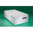

北京欧兰科技发展有限公司为您提供《爆炸产生的激波中三维成像,速度。检测方案(粒子图像测速)》,该方案主要用于其他中三维成像,速度。检测,参考标准--,《爆炸产生的激波中三维成像,速度。检测方案(粒子图像测速)》用到的仪器有时间分辨粒子成像测速系统(TR-PIV)、Imager sCMOS PIV相机、Ekspla PL2230型高能量皮秒激光器、LaVision DaVis 智能成像软件平台
推荐专场


CCD相机/影像CCD
更多


相关方案
更多
该厂商其他方案
更多