


方案详情
文
采用LaVision公司的DaVis8.4软件平台搭建了粒子成像PIV,粒子跟踪测速PTV和平面激光诱导荧光测量平台。并用此平台对分层液-液管流与横流中的射流相互作用进行了测量和研究。
方案详情

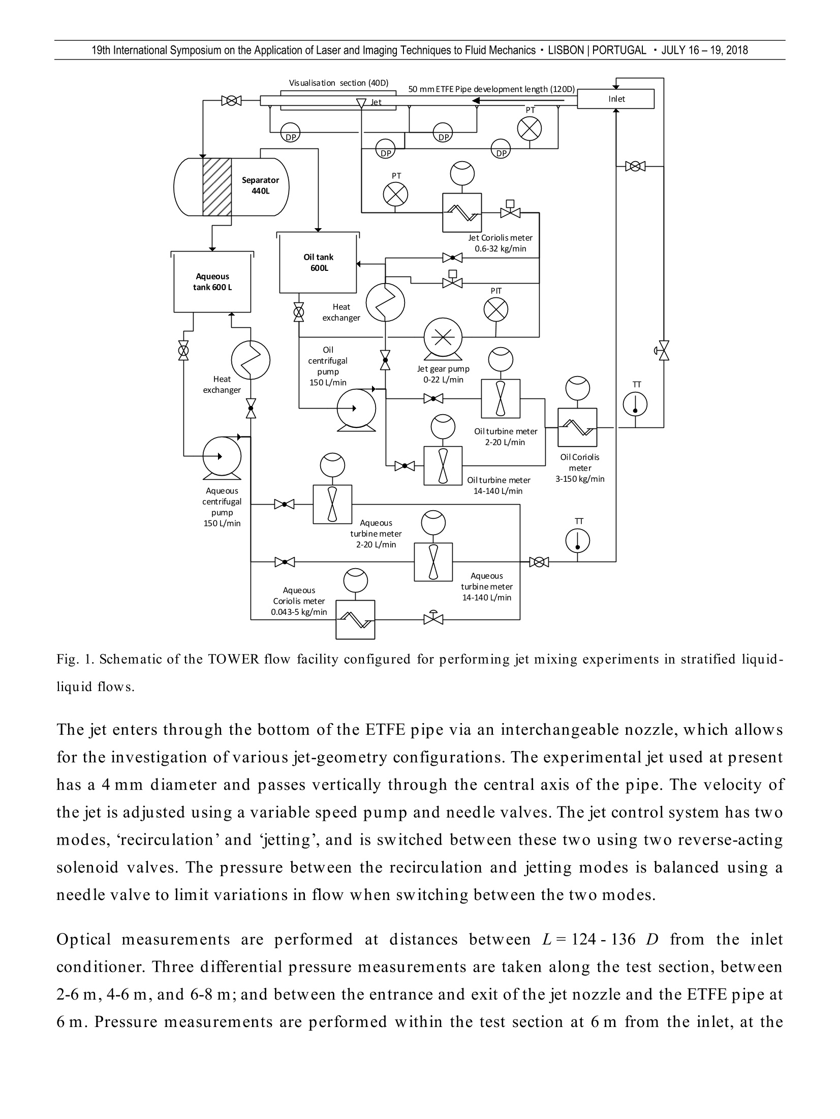
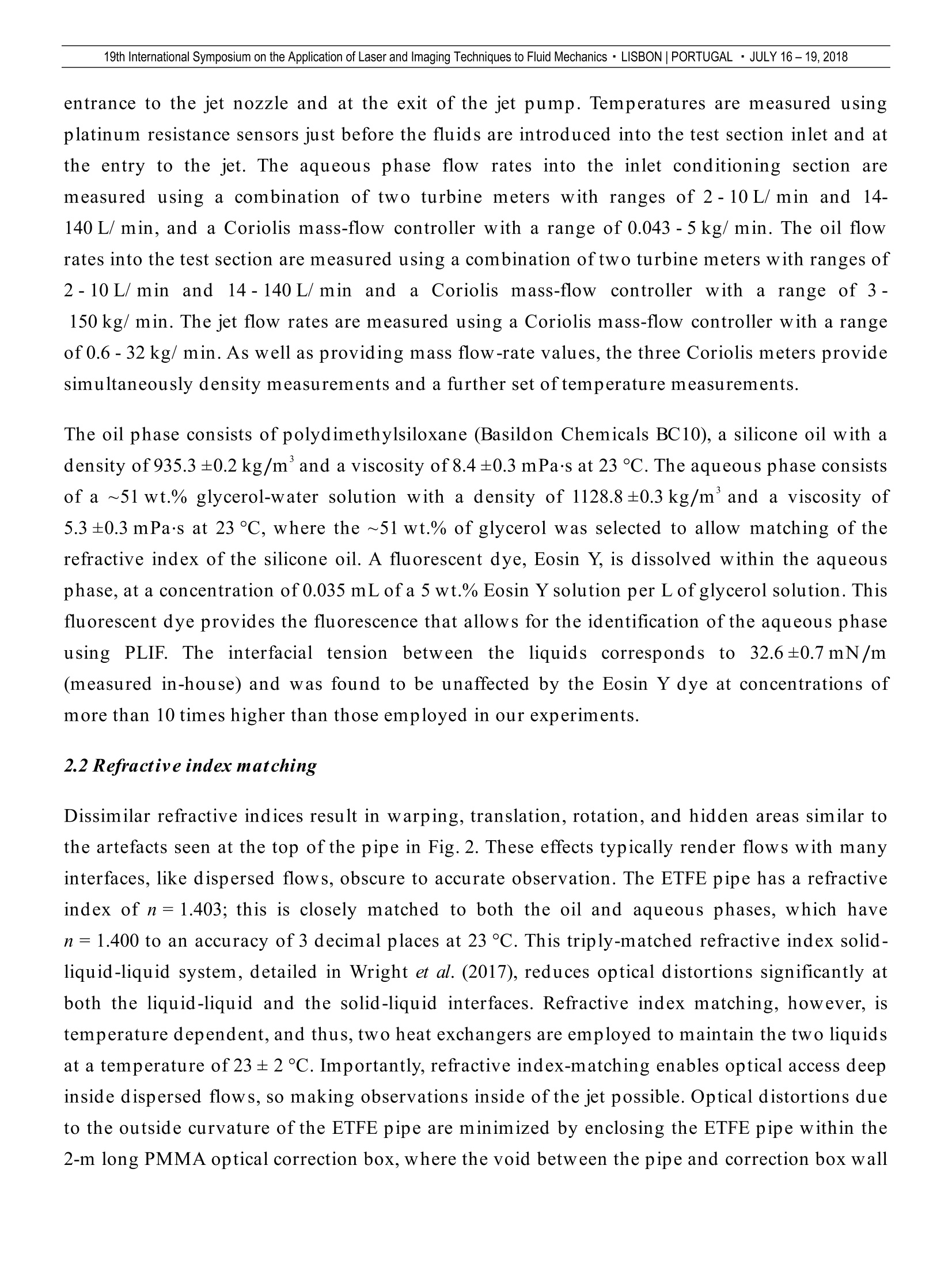
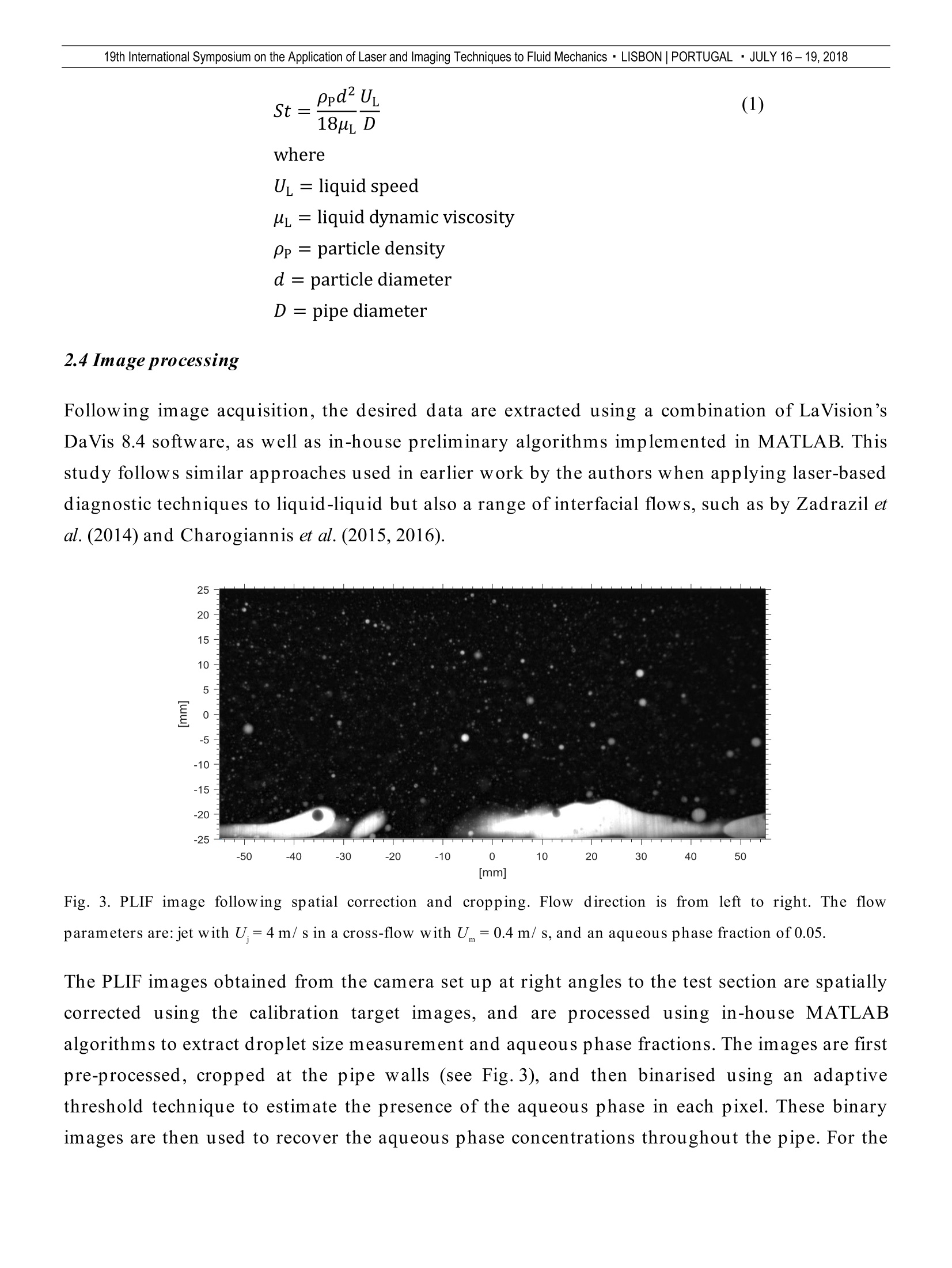
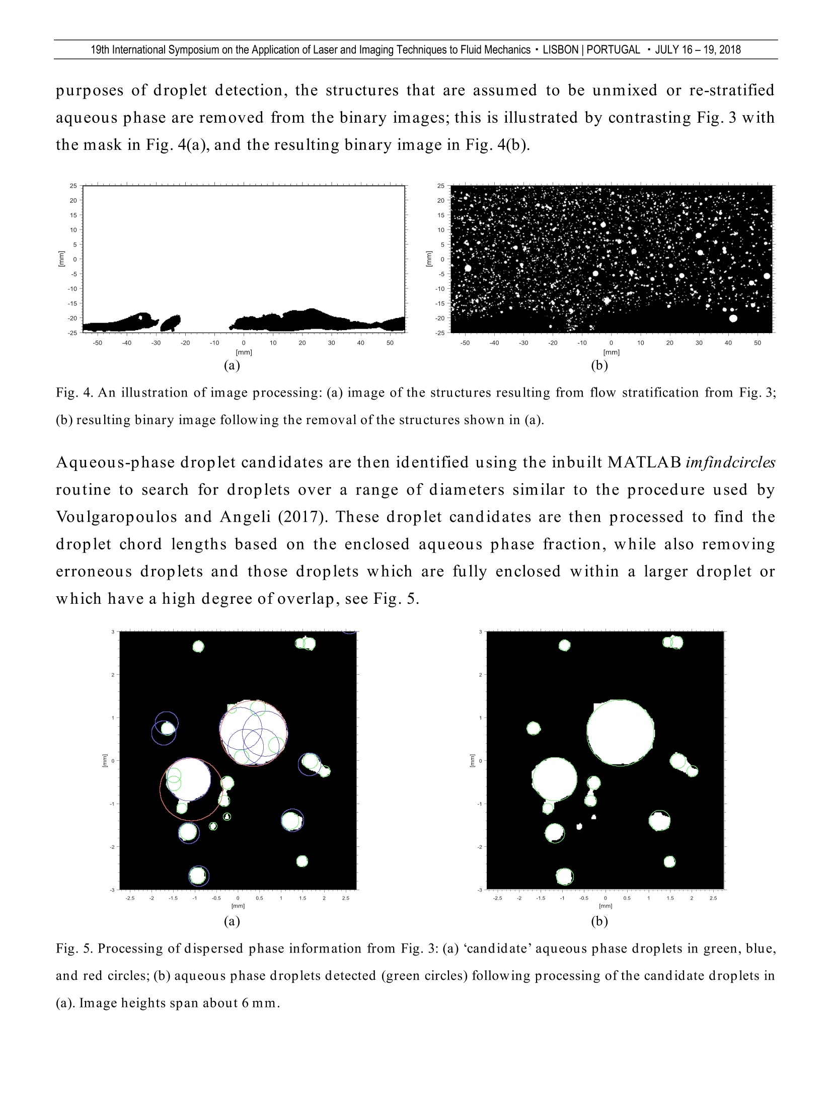
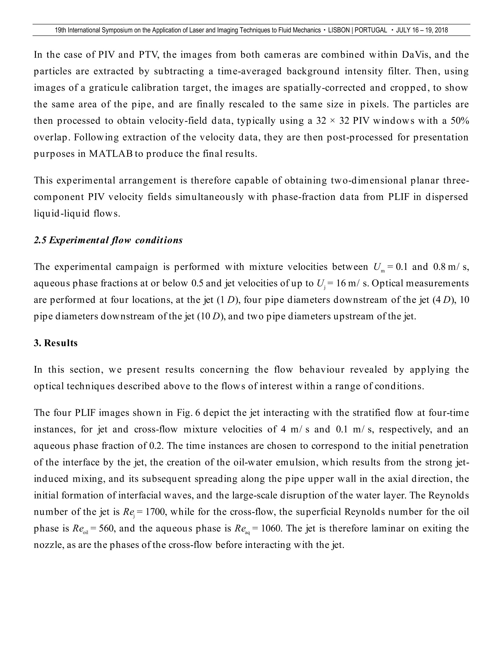
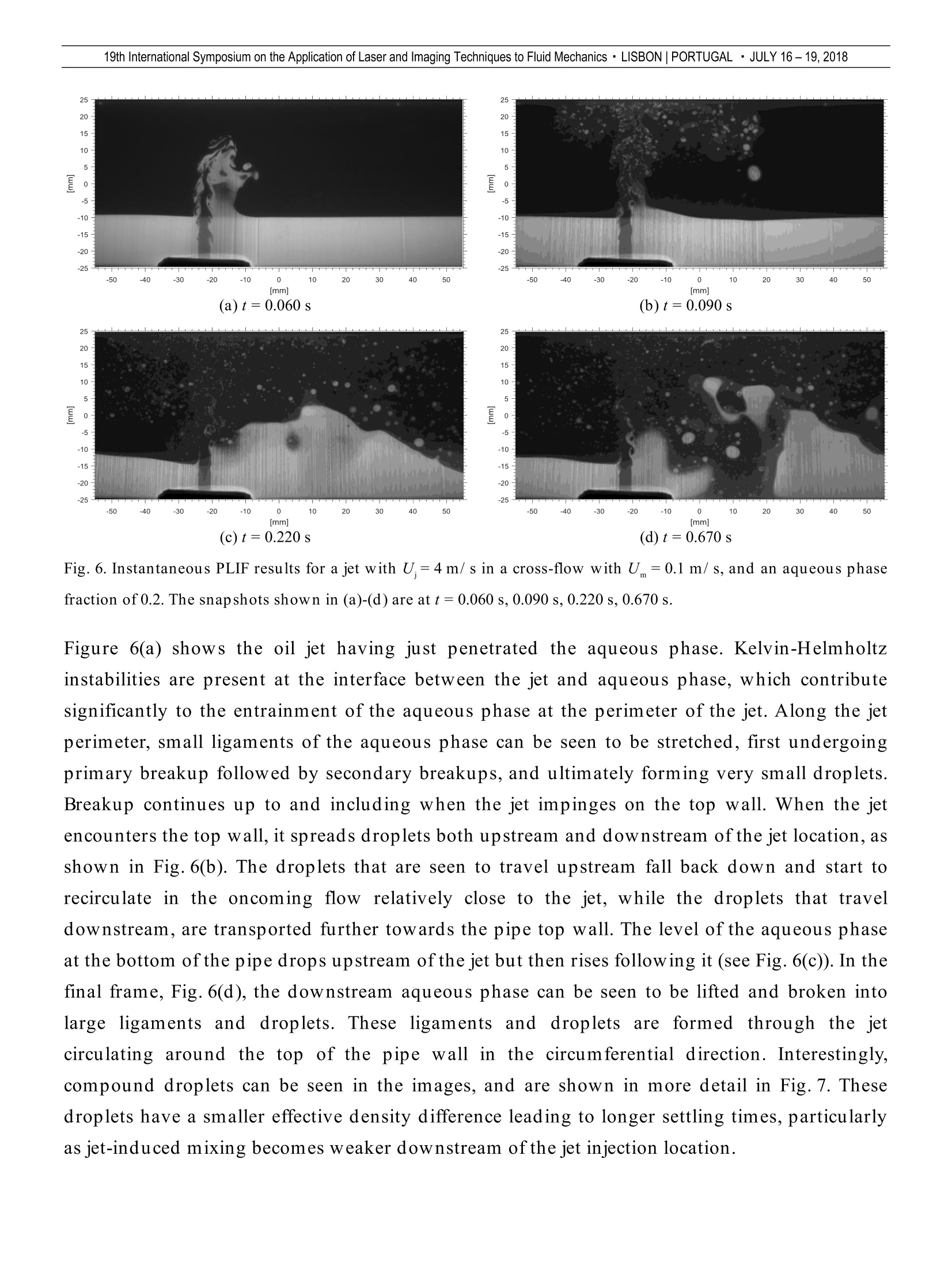
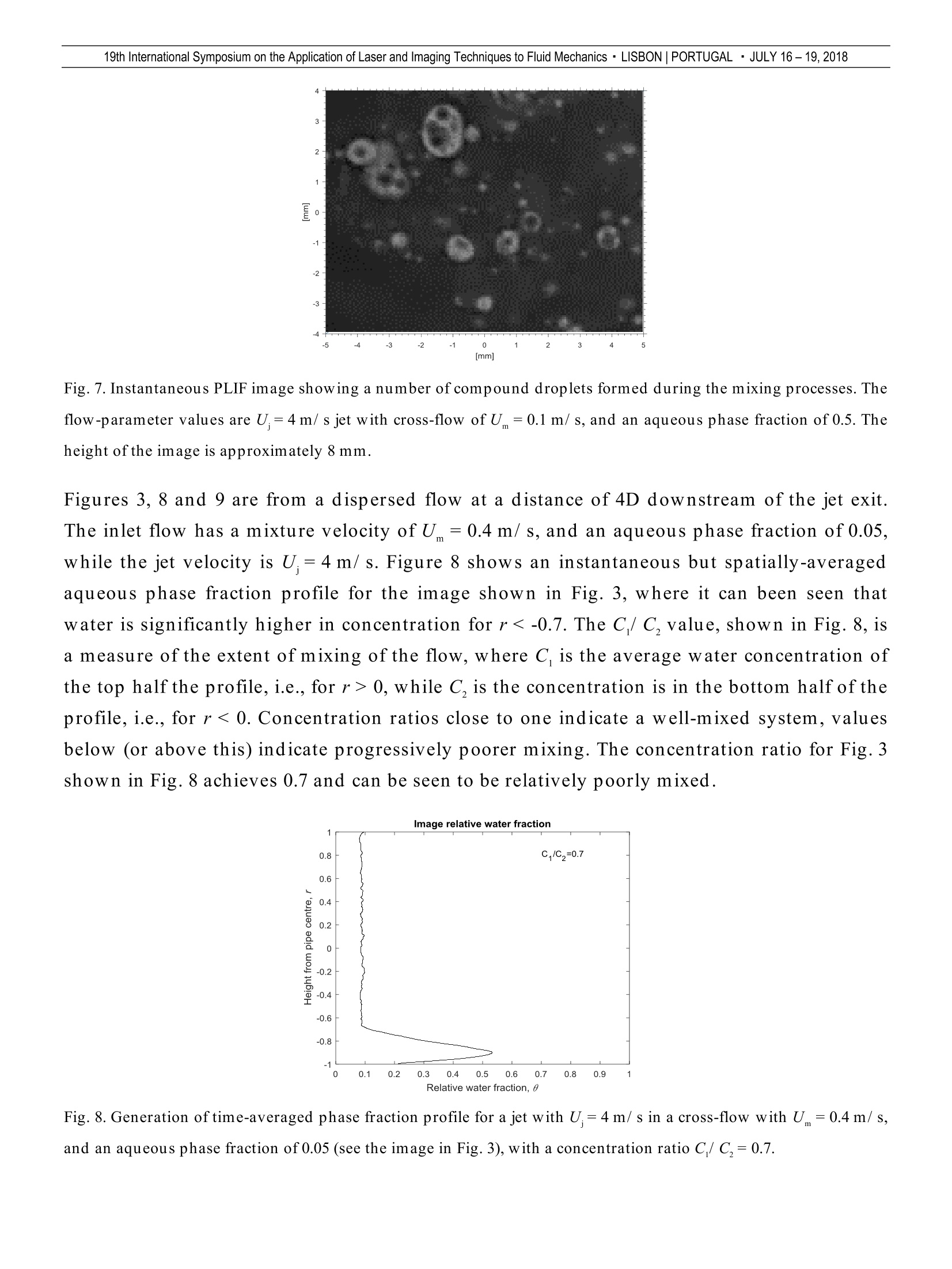
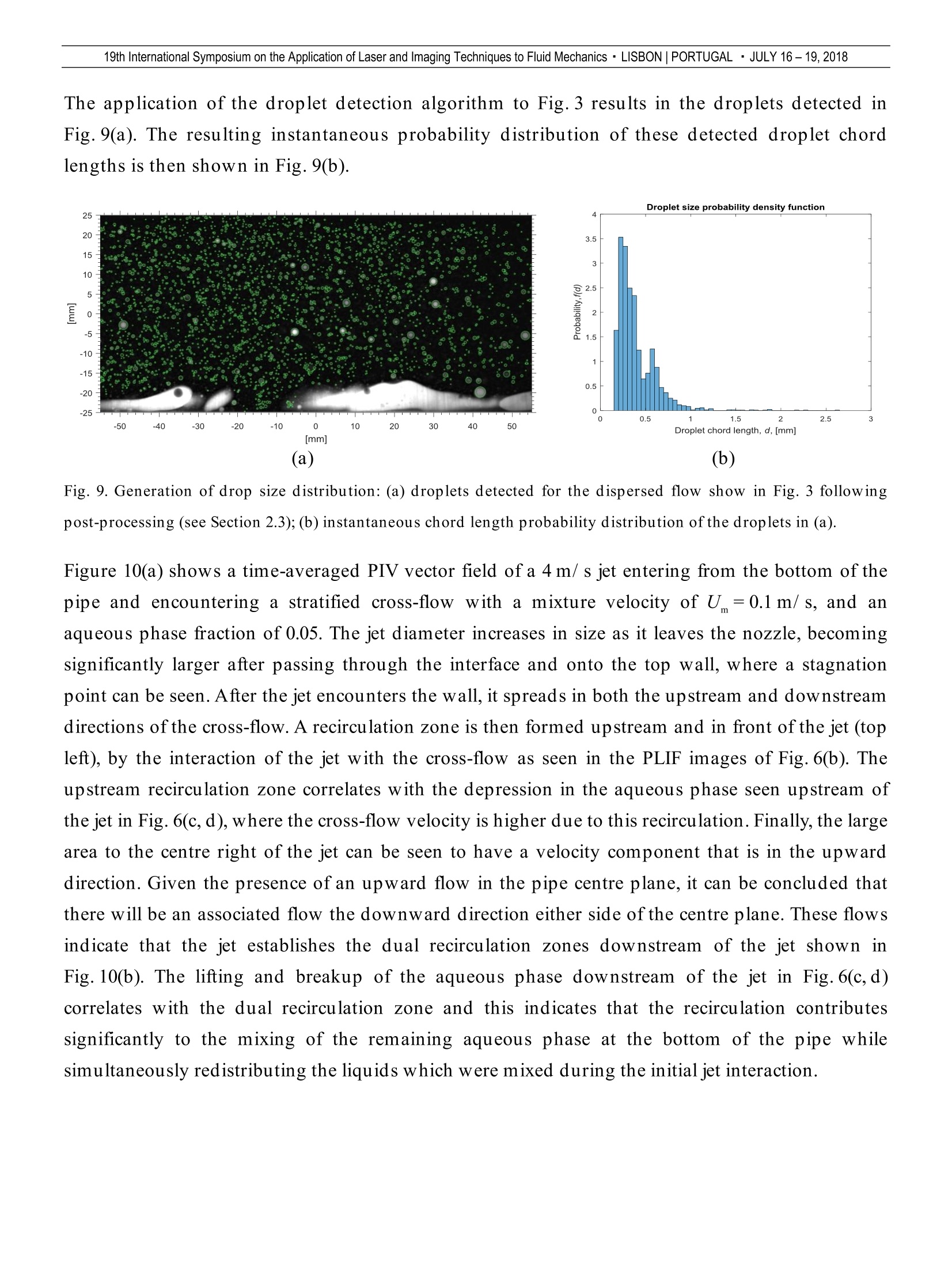
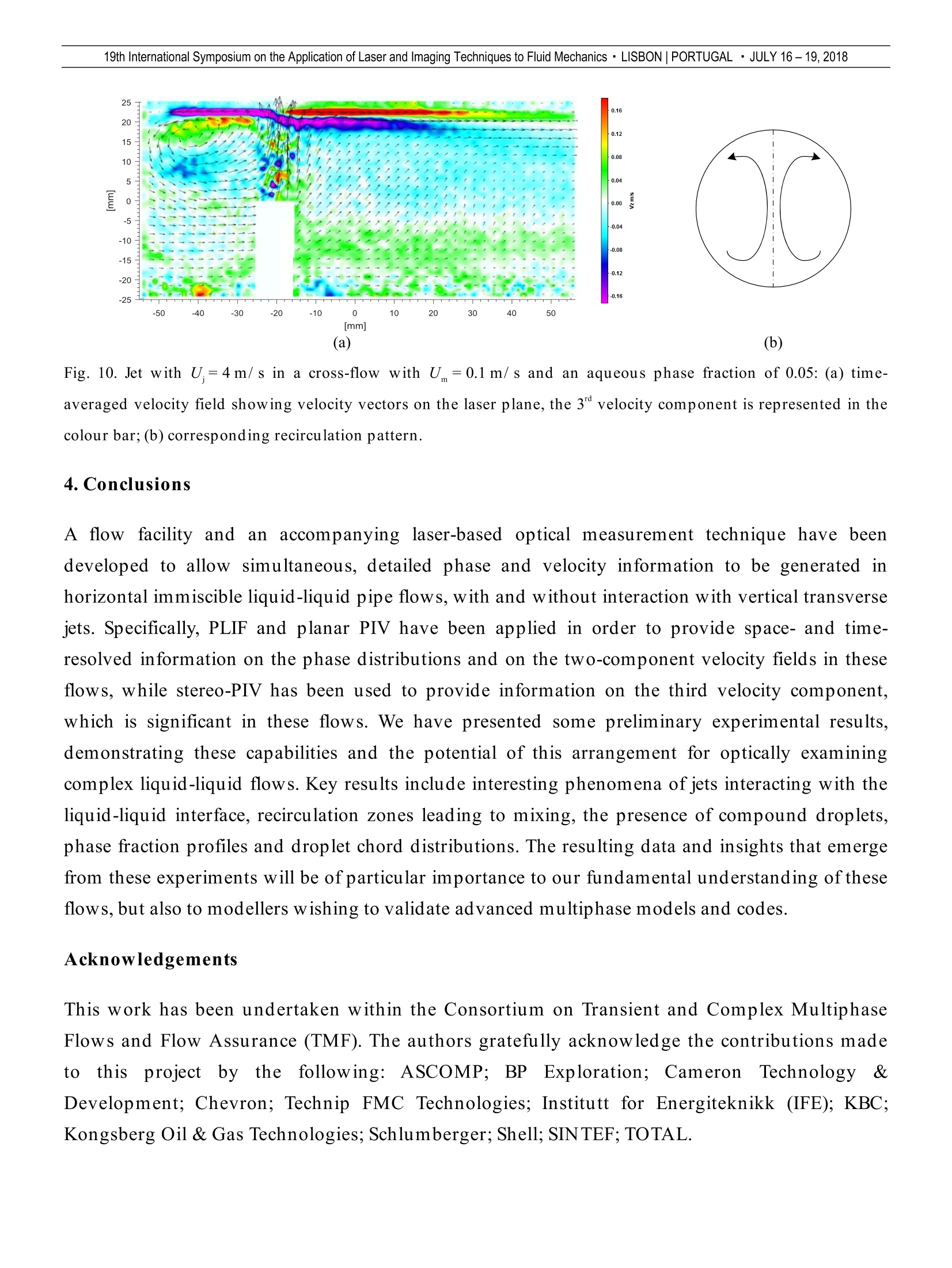
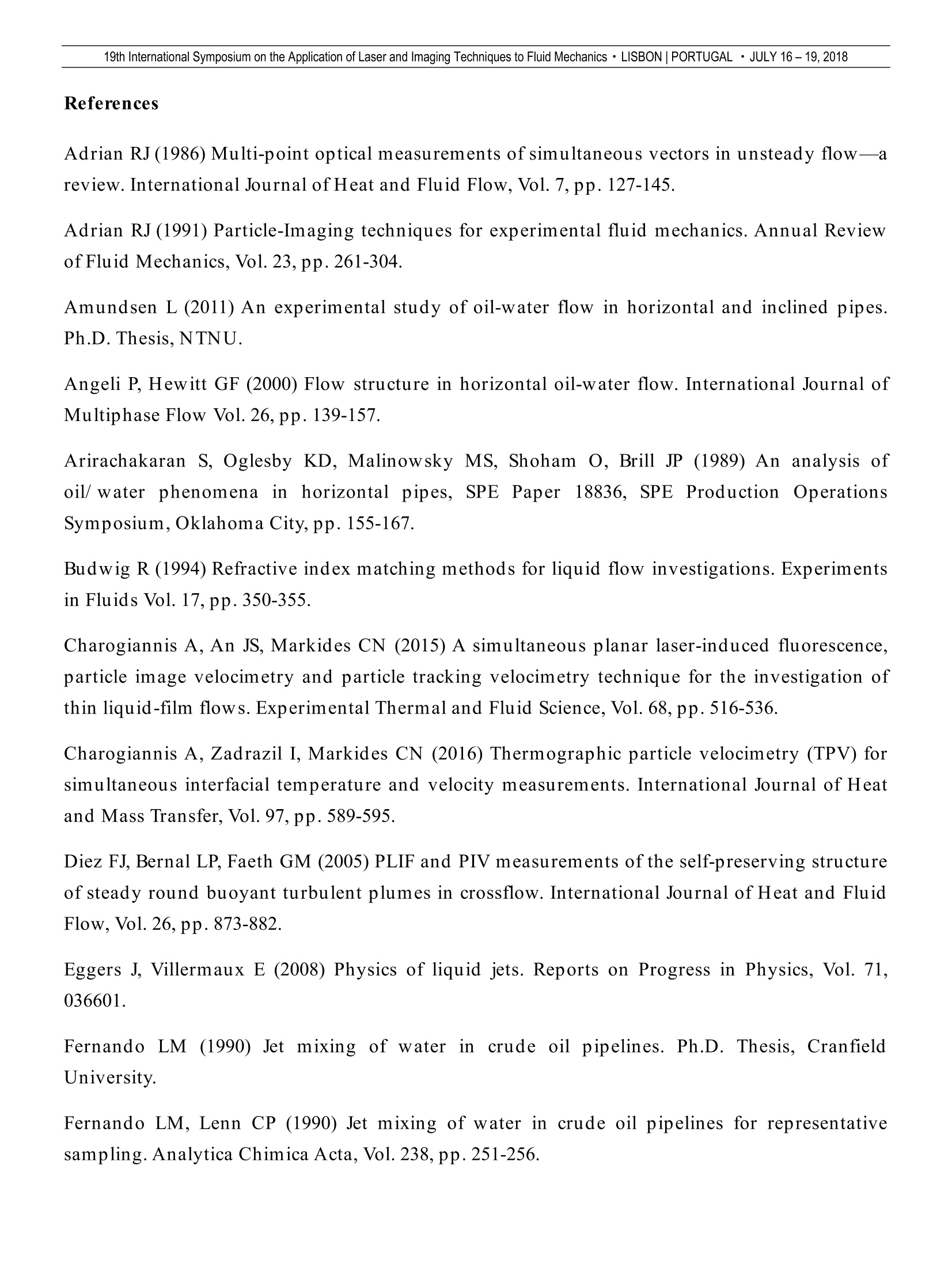
19th International Symposium on the Application of Laser and Imaging Techniques to Fluid Mechanics · LISBON |PORTUGAL·JULY 16-19,2018 Laser-based measurements of stratified liquid-liquid pipe flows interacting withjets in cross-flow Stuart F. Wright1, Alexandros Charogiannis 1, Victor Voulgaropoulos1, Omar K. Matar1, Christos N. Markides11: Department of Chemical Engineering, Imperial College London, London, UK*Corresponding author: c.markides@imperial.ac.uk Keywords: liquid-liquid flows, jets, mixing, particle image velocimetry, laser-induced fluorescence, refractive index matching ABSTRACT At low velocities, horizontal liquid-liquid flows undergo gravitationally-induced stratification, which in manypractical applications complicates significantly the direct measurement of the average properties of the flow.The extent of flow stratification, however, can be limited through inline mixing leading to the formation ofliquid-liquid dispersions with more homogenous properties. In this work, we focus on the use of ‘active’mixing methods using jets in cross flows (JICFs). In this paper, a dedicated experimental flow facility for theinvestigation of such flows is presented, along with the accompanying laser-based optical measurementtechniques and associated algorithms that have been developed for this investigation. The facility allowssimultaneous, space- and time-resolved phase and velocity information to be generated via planar laser-induced fluorescence (PLIF) and particle velocimetry (PIV/PTV), with stereo-PIV used to provide informationonthe thirdd((out-of-plane) velocityy ccoonmponent.Preliminary experimental resultsare presentedwhichdemonstrate the capabilities of thisarrangement for optically examining stratified liquid-liquid flowsinteracting with JICFs, leading to new insights into these complex flows. The key results include phenomena ofjets interacting with the liquid-liquid interface, recirculation zones that lead to further mixing, the presence ofcomplex compound droplets, droplet size distributions, and water concentration profiles. 1. Introduction Immiscible liquid-liquid flows, which typically comprise an organic (oil) phase and an aqueous(water) phase, have been the subject of numerous experimental studies, including those ofRussell et al. (1959), Arirachakaran et al.(1989), Trallero (1995), Soleimani (1999), Amundsen(2011), and have been reviewed recently by Ibarra et al.(2014). Typically, these phases differ indensity and viscosity which, especially at low pipeline velocities, results in the flows undergoinggravitationally-induced separation leading to stratification and variation in the bulk velocitybetween the two liquid phases (Angeli and Hewitt, 2000; Voulgaropoulos 2018). In the oil and gas industry, oil and water mixtures are transported over large distances through horizontalpipelines, and stratification of these phases can lead to corrosion, slugging, metering andvaluation errors. Indeed, stratified flows have no single point where representative samples ormeasurements can be taken and this can lead to significant financial losses due to poor metering. Inline mixing can be used to limit liquid-liquid stratification by promoting oil-water dispersions.However, tight emulsions of these fluids containing fine droplets are undesirable as this leads toincreased downstream separation costs when processing. It is therefore desirable to create shortterm emulsions that homogenize the fluids sufficiently for the extraction ofrepresentative samples.This inline mixing can be either ‘active’or passive’; the latter employs valves or static mixerswhich result in significant pressure losses and the former uses jets in cross-flow (JICF), relying onan external energy source. Although jets have been studied in great depth, as demonstrated in thereviews by Sirignano and Mehring (2000) and Eggers and Villermaux (2008), there is a relativedearth of experimental studies focusing on JICF to mix liquid-liquid pipe flows (Fernando 1990;Fernando and Lenn 1990;Lakshmanan et al.(2015,2017)). Importantly,no previous studies haveexamined the jet interaction and liquid breakup processes optically;this is the focus of our work.Planar laser-induced fluorescence (PLIF) is an optical technique that can be used to differentiatebetween two (or more) liquid phases through a laser-based activation of a fluorescent dyedissolved within one of the phases. Typically, the dye is illuminated in the flow of interest using athin,pulsed laser-sheet, and the resulting images are then captured using a high-speed camera.PLIF has been used extensively in the field, e.g., in the studies of Kinsey (1977), Diez et al. (2005),Ovdat and Berkowitz (2006), and Ravelet et al. (2007). Furthermore, particle velocimetrytechniques such as particle image velocimetry (PIV),using groups of tracer particles, and particletracking velocimetry PTV, using individual tracer particles, can obtain spatiotemporal informationon the velocity fields within flow regions of interest, as described, for instance, by Adrian (1986,1991), and Maas et al. (1992). A single camera setup allows the extraction of the two velocitycomponents that lie parallel to the laser plane, while the inclusion of a second camera, situated onthe same horizontal plane but at a differing angle to the first, allows the extraction of the thirdvelocity component perpendicular to the laser plane. This technique is commonly known as StereoPIV (SPIV) (Arroyo and Greated,1991). SPIV is useful in studying complex pipeline flows wherelarge non-axial flows are present, as is the case in JICF. Morgan et al. (2012,2013,2017) studied horizontal liquid-liquid flows in both a square cross-section channel and a 25.4-mm round pipe using simultaneous 2-D PLIF and PIV/PTV, withPLIF used to identify the phase fractions while, in the same plane, PIV/PTV was used to measure the velocity components in the vertical and horizontal directions in both liquid phases.In this work, the laser sheet was oriented in a vertical plane passing through the centreline of thepipe and the refractive indices of the liquids were matched. Refractive index-matching isimportant in minimizing light distortions (reflections, refractions) at the liquid interfaces (see thereviews of Budwig (1994), and Wright et al. (2017), and references therein). Morgan et al. (2012,2013, 2017) used Exxsol D80 as the oil phase, and then refractive index-matched a glycerol-watermix for the aqueous phase. This required the aqueous phase to have a viscosity considerablyhigher than water, and in fact, higher than that of the oil phase as well. Thus, the viscosity ratiowas reversed compared to typical oil-water flows in oil-and-gas applications. The present work extends the work of Morgan et al. (2012,2013,2017) to include interactions ofstratified horizontal liquid-liquid pipe flows withtransverse jets, for situations wherein theaqueous phase is less viscous than the oil phase, and the viscosity ratio is typical of the majority ofcrude-oil pipe flows, while simultaneously maintaining the densities differences in these flows. 2. Experimental methodology 2.1 Flow facility and instrumentation The experiments were conducted at Imperial College London’s Two-Phase Oil and Water Rig(TOWER), a schematic of which is shown in Fig. 1. The horizontal test-section has a total length of8.5 m, and the pipe has an internal diameter ofD=50 mm. The liquids are introduced into the testsection through a flow inlet conditioning section that comprises a splitter plate positioned 17 mmfrom the bottom of the pipe, along with three meshes and two honeycomb flow straighteners. Theaqueous and oil phases are introduced above and below the separation plate, respectively.Thisinlet conditioning configuration rapidly creates the stratified flows intended for our investigation.Following the inlet conditioner, the liquids pass through a flow development section consisting ofa 6 m ethylene tetrafluoroethylene (ETFE) pipe section. On exiting the flow development section,the stratified liquids enter the optical measurement section, which is a 2-m long ETFE pipeenclosed within a polymethyl methacrylate (PMMA) observation box that also contains the jetnozzle. Upon exiting the observation test section, the mixed liquids are subsequently separatedand returned to their respective tanks allowing for continuous operation ofthe flow facility. Fig. 1. Schematic of the TOWER flow facility configured for performing jet mixing experiments in stratified liquid-liquid flows. The jet enters through the bottom of the ETFE pipe via an interchangeable nozzle, which allowsfor the investigation of various jet-geometry configurations. The experimental jet used at presenthas a 4 mm diameter and passes vertically through the central axis of the pipe. The velocity ofthe jet is adjusted using a variable speed pump and needle valves. The jet control system has twomodes, recirculation’and jetting’, and is switched between these two using two reverse-actingsolenoid valves. The pressure between the recirculation and jetting modes is balanced using aneedle valve to limit variations in flow when switching between the two modes. Optical measurementsare performed at distancesbetweenIL=124-136 D from the inletconditioner. Three differential pressure measurements are taken along the test section, between2-6 m, 4-6 m, and 6-8 m; and between the entrance and exit of the jet nozzle and the ETFE pipe at6 m. Pressure measurements are performed within the test section at 6 m from the inlet, at the entrance to the jet nozzle and at the exit of the jet pump. Temperatures are measured usingplatinum resistance sensors just before the fluids are introduced into the test section inlet and atthe entry to the jet. The aqueous phase flow rates into the inlet conditioning section aremeasured using a combination of two turbine meterssWwith ranges of 2-10L/ min and 14-140 L/ min, and a Coriolis mass-flow controller with a range of 0.043-5 kg/ min. The oil flowrates into the test section are measured using a combination oftwo turbine meters with ranges of2-10L/min and i4-140L/min anda Coriolis mass-flow controller witha jrange of 3-150 kg/ min. The jet flow rates are measured using a Coriolis mass-flow controller with a rangeof 0.6-32kg/ min. As well as providing mass flow-rate values, the three Coriolis meters providesimultaneously density measurements and a further set oftemperature measurements. The oil phase consists of polydimethylsiloxane (Basildon Chemicals BC10), a silicone oil with adensity of 935.3±0.2 kg/m'and a viscosity of 8.4±0.3 mPa.s at 23 ℃. The aqueous phase consistsof a ~51 wt.% glycerol-water solution with a density of 1128.8±0.3 kg/m'and a viscosity of5.3±0.3 mPas at 23 C, where the ~51 wt.% of glycerol was selected to allow matching of therefractive index of the silicone oil. A fluorescent dye, Eosin Y, is dissolved within the aqueousphase, at a concentration of 0.035 mL of a 5 wt.% Eosin Y solution per L of glycerol solution. Thisfluorescent dye provides the fluorescence that allows for the identification of the aqueous phaseusingPLIF.The interfacial tens i betweenthe liquidscorresponds to32.6±0.7mN/m(measured in-house) and was found to be unaffected by the Eosin Y dye at concentrations ofmore than 10 times higher than those employed in our experiments. 2.2 Refractive index matching Dissimilar refractive indices result in warping, translation, rotation, and hidden areas similar tothe artefacts seen at the top of the pipe in Fig. 2. These effects typically render flows with manyinterfaces, like dispersed flows, obscure to accurate observation. The ETFE pipe has a refractiveindex of n= 1.403; this is closely matched to both the oil and aqueous phases, which haven=1.400 to an accuracy of 3 decimal places at 23 C. This triply-matched refractive index solid-liquid-liquid system, detailed in Wright et al. (2017), reduces optical distortions significantly atboth the liquid-liquid and the solid-liquid interfaces. Refractive index matching, however, istemperature dependent, and thus, two heat exchangers are employed to maintain the two liquidsat a temperature of 23±2C. Importantly, refractive index-matching enables optical access deepinside dispersed flows, so making observations inside of the jet possible. Optical distortions dueto the outside curvature of the ETFE pipe are minimized by enclosing the ETFE pipe within the2-m long PMMA optical correction box, where the void between the pipe and correction box wall is filled with the refractive index-matched silicone oil.One of the cameras is set up perpendicularto the observation box to minimize optical distortions, while the second camera is angled slightly(23°) to allow the extraction of the third velocity component using SPIV. Further corrections areobtained through the use of a three-dimensional graticule calibration target, shown in Fig. 2. Thegraticule is imagedwhen installed within the silicone-oil-filled ETFE pipe located in theobservation box. Subsequent processing of the graticule images is used to correremaining distortions and to provide the 3-dimensional spatial calibration of the images. Thelargest corrections are needed due to the mismatch in refractive index at the surface of thePMMA of the observation box (n=1.490) with that ofair (n =1.000). Fig. 2. Image of the graticule used for spatial calibration and optical correction located inside the silicone oil-filledobservation box. The top of the ETFE pipe contains air while the bottom of the pipe contains oil. The aluminium graticule-plate is computer numerical control (CNC) machined to createvertical ridges 2 mm wide, and vertical troughs 3mm wide, with a 1 mm depth differencebetween the ridges and troughs. The graticule is then anodised black, and following anodising,1 mm diameter circular dots are created by carefully removing the thin anodised layer usingaCNC machine. These dots are arranged in two layers where the first layer is on the ridges andthe second layer is on the troughs, and thus the layers are separated by 1 mm in the z-direction.The second layer of dots is also offset to the first layer by 2.5 mm in the x and y directions. Thedots form a grid in each layer so that their centres are spaced 5 mm apart. The resultinggraticule has a positional accuracy of better than 10 um. The graticule calibration dimensionswere selected so that so that there would be ten spatial calibration markers in the vertical axisand the same spacing was then applied to the horizontal axis. The 1 mm depth of the troughswas selected as this was the smallest expected laser sheet thickness. The resulting graticule issimilar in design to the “Type 7' plate provided by LaVision. 2.3 Optical technique and implementation The light source is a dual cavity neodymium-doped yttrium lithium fluoride (Nd:YLF) laser(Litron Lasers LDY 304), producing up to 30 mJ per pulse at 527 nm with a maximum repetitionrate of 20 kHz. A laser-guiding arm and Dantec Dynamics sheet-optics are used to expand theroughly circular laser beam into a 1- to 2-mm thick sheet at the measurement location. The lasersheet is set up so that it enters through the top ofthe pipe in a vertical plane that is oriented to passthrough the centreline of the pipe and along the pipe axis. This laser sheet is used to illuminatetracer particles located in both phases while also exciting the Eosin Y dye in the aqueous phase. The resulting images are captured using two monochromatic Olympus iSpeed3 cameras, whichhave a resolution of 1280 ×1024 at a maximum frame rate of2 kHz, providing a field ofview of~2 Din the horizontal plane resulting in a resolution of~80 pm per pixel. Each laser pulse is synchronizedwith the shutters for the two cameras so that a single laser pulse illuminates the images in bothcameras for simultaneous capture of the flow phenomena. One camera is located perpendicular tothe observation box and collects the particle and PLIF information with little distortion. This camerauses a Nikon AF Micro NIKKOR 60mm f/ 2.8D lens and when performing higher contrast PLIFonly measurements a 540 nm low pass filter (LP540) is used. The second camera uses a Sigma105 mm f/ 2.8 EXDG Macro lens, along with a Scheimpflug mount to allow the camera to focus ontoa laser sheet tilted from the perpendicular. This angled camera was then used to collect particleposition data to extract the (stereo) velocity component, perpendicular to the laser sheet whenmaking SPIV measurements. The Scheimpflug and lens arrangement along with the difference inrefractive-indices at the observation box surfaces and desired field of view, limit the angle at whichthe image can be maintained in focus to a maximum of 23° to the perpendicular. Tracer particles were selected for the PIV/PTV measurements based on cost, hydrophobicity,Stokes number (equation 1), density and apparent particle image size. The oil phase was seededwith 100-um diameter oleophilic silver-coated hollow ceramic spheres (SHCS) (Hart materialsAGSL 150-16-16-TRD) with a density of900 kg/ m3. The aqueous phase was seeded with 100-umdiameter hydrophilic polyamide spheres from LaVision, with a density of 1100 kg/ m. 19th International Symposium on the Application of Laser and Imaging Techniques to Fluid Mechanics· LISBON|PORTUGAL · JULY 16- 19, 2018 whereUt = liquid speed=liquid dynamic viscosityPp= particle density d= particle diameter D = pipe diameter 2.4 Image processing Following image acquisition, the desired data are extracted using a combination of LaVision’sDaVis 8.4 software, as well as in-house preliminary algorithms implemented in MATLAB. Thisstudy follows similar approaches used in earlier work by the authors when applying laser-baseddiagnostic techniques to liquid-liquid but also a range of interfacial flows, such as by Zadrazil etal.(2014) and Charogiannis et al.(2015,2016). EE Fig. 3. PLIF image following spatial correction and cropping. Flow direction is from left to right. The flowparameters are: jet with U= 4 m/ s in a cross-flow with U =0.4 m/s, and an aqueous phase fraction of 0.05. The PLIF images obtained from the camera set up at right angles to the test section are spatiallycorrrected using the calibration target images,and are processed using in-house MATLABalgorithms to extract droplet size measurement and aqueous phase fractions. The images are firstpre-processed, cropped at the pipe walls (see Fig.3), and then binarised using an adaptivethreshold technique to estimate the presence of the aqueous phase in each pixel. These binaryimages are then used to recover the aqueous phase concentrations throughout the pipe. For the purposes of droplet detection, the structures that are assumed to be unmixed or re-stratifiedaqueous phase are removed from the binary images; this is illustrated by contrasting Fig. 3 withthe mask in Fig. 4(a), and the resulting binary image in Fig.4(b). Fig. 4. An illustration of image processing: (a) image of the structures resulting from flow stratification from Fig. 3;(b) resulting binary image following the removal of the structures shown in (a). Aqueous-phase droplet candidates are then identified using the inbuilt MATLAB imfindcirclesroutine to search for droplets over a range of diameters similar to the procedure used byVoulgaropoulos and Angeli (2017). These droplet candidates are then processed to find thedroplet chord lengths based on the enclosed aqueous phase fraction, while also removingerroneous droplets and those droplets which are fully enclosed within a larger droplet orwhich have a high degree of overlap, see Fig. 5. (b) Fig. 5. Processing of dispersed phase information from Fig. 3: (a)candidate'aqueous phase droplets in green,blue,and red circles; (b) aqueous phase droplets detected (green circles) following processing of the candidate droplets in(a). Image heights span about 6mm. In the case of PIV and PTV, the images from both cameras are combined within DaVis, and theparticles are extracted by subtracting a time-averaged background intensity filter. Then, usingimages of a graticule calibration target, the images are spatially-corrected and cropped, to showthe same area of the pipe,and are finally rescaled to the same size in pixels. The particles arethen processed to obtain velocity-field data, typically using a 32 x 32 PIV windows with a 50%overlap. Following extraction of the velocity data, they are then post-processed for presentationpurposes in MATLAB to produce the final results. This experimental arrangement is therefore capable of obtaining two-dimensional planar three-component PIV velocity fields simultaneously with phase-fraction data from PLIF in dispersedliquid-liquid flows. 2.5 Experimental flow conditions The experimental campaign is performed with mixture velocities between U =0.1 and 0.8 m/ s,aqueous phase fractions at or below 0.5 and jet velocities ofup to U =16 m/ s. Optical measurementsare performed at four locations, at the jet (1 D), four pipe diameters downstream of the jet (4D), 10pipe diameters downstream ofthe jet (10 D), and two pipe diameters upstream ofthe jet. 3. Results In this section, we present results concerning the flow behaviour revealed by applying theoptical techniques described above to the flows of interest within a range of conditions. The four PLIF images shown in Fig. 6 depict the jet interacting with the stratified flow at four-timeinstances, for jet and cross-flow mixture velocities of 4 m/s and 0.1 m/s, respectively, and anaqueous phase fraction of 0.2. The time instances are chosen to correspond to the initial penetrationof the interface by the jet, the creation of the oil-water emulsion, which results from the strong jet-induced mixing, and its subsequent spreading along the pipe upper wall in the axial direction, theinitial formation of interfacial waves, and the large-scale disruption of the water layer. The Reynoldsnumber of the jet is Re=1700, while for the cross-flow, the superficial Reynolds number for the oilphase is Re =560, and the aqueous phase is Re=1060. The jet is therefore laminar on exiting thenozzle, as are the phases ofthe cross-flow before interacting with the jet. E [mm] (a)t=0.060 s (b)t=0.090 s EE Fig. 6. Instantaneous PLIF results for a jet with U =4 m/ s in a cross-flow with U =0.1 m/s, and an aqueous phasefraction of0.2. The snapshots shown in (a)-(d) are at t=0.060 s, 0.090 s, 0.220 s, 0.670 s. Figure 6(a) shows the oil jet having just penetrated the aqueous phase. Kelvin-Helmholtzinstabilities are present at the interface between the jet and aqueous phase, which contributesignificantly to the entrainment of the aqueous phase at the perimeter of the jet. Along the jetperimeter, small ligaments of the aqueous phase can be seen to be stretched, first undergoingprimary breakup followed by secondary breakups, and ultimately forming very small droplets.Breakup continues up to and including when the jet impinges on the top wall. When the jetencounters the top wall, it spreads droplets both upstream and downstream ofthe jet location, asshown in Fig. 6(b). The droplets that are seen to travel upstream fall back down and start torecirculate in the oncoming flow relatively close to the jet, while the droplets that traveldownstream, are transported further towards the pipe top wall. The level of the aqueous phaseat the bottom of the pipe drops upstream ofthe jet but then rises following it (see Fig. 6(c)). In thefinal frame, Fig.6(d), the downstream aqueous phase can be seen to be lifted and broken intolarge ligaments and droplets.. These ligaments anddroplets are formed through the jetcirculating around the top of the pipe wall in the circumferential direction. Interestingly,compound droplets can be seen in the images, and are shown in more detail in Fig. 7. Thesedroplets have a smaller effective density difference leading to longer settling times, particularlyas jet-induced mixing becomes weaker downstream ofthe jet injection location. 19th International Symposium on the Application of Laser and Imaging Techniques to Fluid Mechanics · LISBON| PORTUGAL · JULY 16- 19, 2018 Fig. 7. Instantaneous PLIF image showing a number of compound droplets formed during the mixing processes. Theflow-parameter values are U =4 m/s jet with cross-flow of U =0.1 m/ s, and an aqueous phase fraction of 0.5. Theheight of the image is approximately 8 mm. Figures 3, 8 and 9 are from a dispersed flow at a distance of 4D downstream of the jet exit.The inlet flow has a mixture velocity of U =0.4 m/s, and an aqueous phase fraction of 0.05,while the jet velocity is U =4 m/ s. Figure 8 shows an instantaneous but spatially-averagedaqueous phase fraction profile for the image shown in Fig. 3, where it can been seen thatwater is significantly higher in concentration for r <-0.7. The C/ C, value, shown in Fig. 8, isa measure of the extent of mixing of the flow, where C is the average water concentration ofthe top half the profile, i.e., for r> 0, while C, is the concentration is in the bottom half of theprofile, i.e., for r <0. Concentration ratios close to one indicate a well-mixed system, valuesbelow (or above this) indicate progressively poorer mixing. The concentration ratio for Fig.3shown in Fig. 8 achieves 0.7 and can be seen to be relatively poorly mixed. Fig. 8. Generation oftime-averaged phase fraction profile for a jet with U= 4 m/ s in a cross-flow with U =0.4m/ s,and an aqueous phase fraction of 0.05 (see the image in Fig. 3), with a concentration ratio C,/ C,=0.7. The application of the droplet detection algorithm to Fig.3 results in the droplets detected inFig.9(a). The resulting instantaneous probability distribution of these detected droplet chordlengths is then shown in Fig.9(b). Fig. 9. Generation of drop size distribution: (a) droplets detected for the dispersed flow show in Fig. 3 followingpost-processing (see Section 2.3); (b) instantaneous chord length probability distribution of the droplets in (a). Figure 10(a) shows a time-averaged PIV vector field of a 4 m/s jet entering from the bottom of thepipe and encountering a stratified cross-flow with a mixture velocity of U =0.1 m/ s, and anaqueous phase fraction of 0.05. The jet diameter increases in size as it leaves the nozzle, becomingsignificantly larger after passing through the interface and onto the top wall, where a stagnationpoint can be seen. After the jet encounters the wall, it spreads in both the upstream and downstreamdirections of the cross-flow. A recirculation zone is then formed upstream and in front of the jet (topleft), by the interaction of the jet with the cross-flow as seen in the PLIF images of Fig.6(b). Theupstream recirculation zone correlates with the depression in the aqueous phase seen upstream ofthe jet in Fig. 6(c, d), where the cross-flow velocity is higher due to this recirculation. Finally, the largearea to the centre right of the jet can be seen to have a velocity component that is in the upwarddirection. Given the presence of an upward flow in the pipe centre plane, it can be concluded thatthere will be an associated flow the downward direction either side of the centre plane. These flowsindicate that the jet establishes the dual recirculation zones downstream of the jet shown inFig. 10(b). The lifting and breakup of the aqueous phase downstream of the jet in Fig.6(c,d)correlates with the dual recirculation zone and this indicates that the recirculation contributessignificantly to the mixing of the remaining aqueous phase at the bottom of the pipe whilesimultaneously redistributing the liquids which were mixed during the initial jet interaction. 19th International Symposium on the Application of Laser and Imaging Techniques to Fluid Mechanics · LISBON|PORTUGAL · JULY 16-19,2018 (a) (b) Fig. 10. Jet with U=4m/s in a cross-flow with U =0.1m/s and an aqueous phase fraction of 0.05: (a) time-averaged velocity field showing velocity vectors on the laser plane, the 3 velocity component is represented in thecolour bar; (b) corresponding recirculation pattern. 4. Conclusions A flow facility and an accompanying laser-based optical measurement technique have beendeveloped to allow simultaneous, detailed phase and velocity information to be generated inhorizontal immiscible liquid-liquid pipe flows, with and without interaction with vertical transversejets. Specifically, PLIF and planar PIV have been applied in order to provide space- and time-resolved information on the phase distributions and on the two-component velocity fields in theseflows, while stereo-PIV has been used to provide information on the third velocity component,which is significant in these flows. We have presented some preliminary experimental results,demonstrating these capabilities and the potential of this arrangement for optically examiningcomplex liquid-liquid flows. Key results include interesting phenomena of jets interacting with theliquid-liquid interface, recirculation zones leading to mixing, the presence of compound droplets,phase fraction profiles and droplet chord distributions. The resulting data and insights that emergefrom these experiments will be of particular importance to our fundamental understanding of theseflows, but also to modellers wishing to validate advanced multiphase models and codes. Acknowledgements This work has been undertaken within the Consortium on Transient and Complex MultiphaseFlows and Flow Assurance (TMF). The authors gratefully acknowledge the contributions madeto thisprojectby the ffollowing: ASCOMP;BP Exploration; Cameron Technology&Development; Chevron; Technip FMC Technologies; Institutt for Energiteknikk(IFE); KBC;Kongsberg Oil & Gas Technologies; Schlumberger; Shell; SIN TEF;TOTAL. References Adrian RJ (1986) Multi-point optical measurements of simultaneous vectors in unsteady flow-areview. International Journal of Heat and Fluid Flow,Vol. 7,pp. 127-145. Adrian RJ (1991) Particle-Imaging techniques for experimental fluid mechanics. Annual Reviewof Fluid Mechanics, Vol.23,pp. 261-304. Amundsen L (2011) An experimental study of oil-water flow in horizontal and inclined pipes.Ph.D.Thesis,NTNU. Angeli P, Hewitt GF (2000) Flow structure in horizontal oil-water flow. International Journal ofMultiphase Flow Vol. 26, pp. 139-157. Arirachakaran S, Oglesby KD, Malinowsky MS, Shoham O, Brill JP (1989) An analysis ofoil/ water phenomena in horizontal pipes, SPE Paper 18836, SPE Production OperationsSymposium,Oklahoma City, pp. 155-167. Budwig R (1994) Refractive index matching methods for liquid flow investigations. Experimentsin Fluids Vol. 17,pp.350-355. Charogiannis A, An JS, Markides CN (2015) A simultaneous planar laser-induced fluorescence,particle image velocimetry and particle tracking velocimetry technique for the investigation ofthin liquid-film flows. Experimental Thermal and Fluid Science, Vol. 68,pp.516-536. Charogiannis A, Zadrazil I, Markides CN (2016) Thermographic particle velocimetry (TPV) forsimultaneous interfacial temperature and velocity measurements. International Journal of Heatand Mass Transfer, Vol. 97,pp.589-595. Diez FJ, Bernal LP, Faeth GM (2005) PLIF and PIV measurements of the self-preserving structureof steady round buoyant turbulent plumes in crossflow. International Journal of Heat and FluidFlow, Vol. 26,pp.873-882. Eggers J, Villermaux E (2008) Physics of liquid jets. Reports on Progress in Physics, Vol. 71,036601. Fernando LM (1990) Jet mixing of water in crude oil pipelines. Ph.D. Thesis, CranfieldUniversity. Fernando LM, Lenn CP (1990) Jet mixing of water in crude oil pipelines for representativesampling.Analytica Chimica Acta, Vol. 238,pp. 251-256. Ibarra R, Markides CN, Matar OK (2014) A review of liquid-liquid flow patterns in horizontaland slightly inclined pipes. Multiphase Science and Technology, Vol. 26, pp. 171-198. Ibarra R, Zadrazil , Matar OK, Markides CN (2017) Dynamics of liquid-liquid flows inhorizontal pipes using simultaneous two-line planar laser-induced fluorescence and particlevelocimetry. Multiphase Science and Technology, Vol.101,pp.47-63. Kinsey JL (1977) Laser-Induced Fluorescence. Annual Review of Physical Chemistry, Vol. 28,pp.349-372. Kumara WAS, Halvorsen BM, Melaaen MC (2010) Particle image velocimetry for characterizingthe flowstructure of oil-water flow in horizontalandslightly inclined pipes. ChemicalEngineering Science, Vol.65,pp.4332-4349. LakshmananS, Holland D, Sederman A, GurevichM, Marui W (2015) Multiphase flowquantification using computational fluid dynamics and magnetic resonance imaging. 33rdInternational North Sea Flow Measurement Workshop. Tonsberg,Norway. Lakshmanan S, Maru WA, Holland DJ, Mantle MD, Sederman AJ (2017) Measurement of an oil-water flow using magnetic resonance imaging. Flow Measurement and Instrumentation, Vol. 53,pp.161-171. Maas HG, Gruen A, Papantoniou D (1993) Particle tracking velocimetry in three-dimensionalflows. Experiments in Fluids,Vol. 15, pp.133-146. Markides CN, Mathie R, Charogiannis A (2016) An experimental study of spatiotemporallyresolved heat transfer in thin liquid-film flows falling over an inclined heated foil. InternationalJournal of Heat and Mass Transfer, Vol. 93,pp.872-888. MorganRG, MarkidesCN, Halee (CP, Hewittt GF (2012)Horizonta1l liquid-liquidflowcharacteristicsatlowr superficial velocities uusing laser-induced ffluorescence. InternationalJournalof Multiphase Flow, Vol. 43,pp.101-117. Morgan RG, Markides CN, Zadrazil I, Hewitt GF (2013) Characteristics of horizontal liquid-liquid flows in a circular pipe using simultaneous high-speed laser-induced fluorescence andparticle velocimetry. International Journal of Multiphase Flow, Vol. 49, pp.99-118. Morgan RG, Ibarra R, Zadrazil I, Matar OK, Hewitt GF, Markides CN (2017) On the role ofbuoyancy-driven instabilitiesinhorizonta1liquid-liquidflow. InternationalJournalofMultiphase Flow, Vol.89, pp. 123-135. Ovdat H, Berkowitz B (2006) Pore-scale study of drainage displacement under combinedcapillary and gravity effects in index-matched porous media. Water Resources Research, Vol. 42,W06411. Ravelet F, Delfos R, Westerweel J (2007) Experimental studies of liquid-liquid dispersion in aturbulent shear flow. 11th EUROMECH European Turbulence Conference. Porto, Portugal. Russell TWF, Hodgson GW, Govier GW (1959) Horizontal pipeline flow of mixtures of oil andwater. Canadian. Journal of Chemical. Engineering. Vol. 37, pp. 9-17. Sirignano WA, Mehring, C (2000) Review of theory of distortion and disintegration of liquidstreams. Progress in Energy and Combustion Science, Vol. 26, pp.609-655. Soleimani A (1999) Phase distribution andassociatedphenomena on oil-waterrflowsinhorizontal tubes. Ph.D., Imperial College London. Trallero JL (1995) Oil-Water Flow Pattern in Horizontal Pipes. Ph.D. Thesis, The University ofTulsa. Voulgaropouloss V (2018)Dynamicsof spatiallyevolvingdispersedd fflows..Ph.D. Thesis.University College London. Voulgaropoulos V, Angeli P (2017) Optical measurementss in evolving dispersed pipe flows.Experiments in Fluids, 58. Wright SF, Zadrazil I, Markides CN (2017) A review of solid-fluid selection options for optical-based measurements in single-phase liquid,two-phase liquid-liquid and multiphase solid-liquidflows. Experiments in Fluids, Vol.58,108. Zadrazil I, Matar OK, Markides CN (2014) An experimental characterization of downwards gas-liquid annular flow by laser-induced fluorescence: Flow regimes and film statistics. InternationalJournal of Multiphase Flow,Vol. 60, 87-102. Zadrazil I, Markides CN (2014) An experimental characterization ofliquid films in downwardsco-current gas-liquid annular flow by particle image and tracking velocimetry. InternationalJournal of Multiphase Flow, Vol. 67, 42-53. At low velocities, horizontal liquid liquid flows undergo gravitationally induced stratification which in many practical applications complicates significantly the direct measurement of the average properties of the flow. The extent of flow stratification however, can be limited through inline mixing leading to the formation of liquid liquid dispersions with more homogenous properties In this work we focus on the use of a ctive mixing methods using jets in cross flows JICFs In this paper, a dedicated experimental flow facility for the investigation of such flows is presented along with the accompanying laser based optical measurementtechniques and asso ciated algorithms that have been developed for this investigation The facility allows simultaneous, space and time resolved phase and velocity information to be generated via planar laser induced fluorescence ( and particle velocimetry (PIV/ with stereo PIV used to provide information on the third (out of plane) velocity component. Preliminary experimental results are presented which demonstrate the capabilities of this arrangement for optically examining stratified liquid liquid flows interacting with JICFs, leading to new insights into these complex flows The key results include phenomena of jets interacting with the liquid- liquid interface, recirculation zones that lead to further mixing, the presence of complex compound droplets, droplet size distributions and water concentration profiles.
确定

还剩15页未读,是否继续阅读?

产品配置单


北京欧兰科技发展有限公司为您提供《液-液管流与横流中的射流中PIV,PLIF, 粒径检测方案(CCD相机)》,该方案主要用于其他中PIV,PLIF, 粒径检测,参考标准--,《液-液管流与横流中的射流中PIV,PLIF, 粒径检测方案(CCD相机)》用到的仪器有LaVision HighSpeedStar 高帧频相机、时间分辨粒子成像测速系统(TR-PIV)、PLIF平面激光诱导荧光火焰燃烧检测系统、LaVision DaVis 智能成像软件平台
推荐专场
CCD相机/影像CCD
更多


相关方案
更多
该厂商其他方案
更多