


方案详情
文
采用LaVision的高速图像增强器HS-IRO,Photron SA1.1 高速CMOS相机,以及SIRAH Credo型高速染料激光器,构成了一套时间分辩高速平面激光诱导荧光测量系统。并用这套系统研究了引燃对湍流火焰结构的影响
方案详情

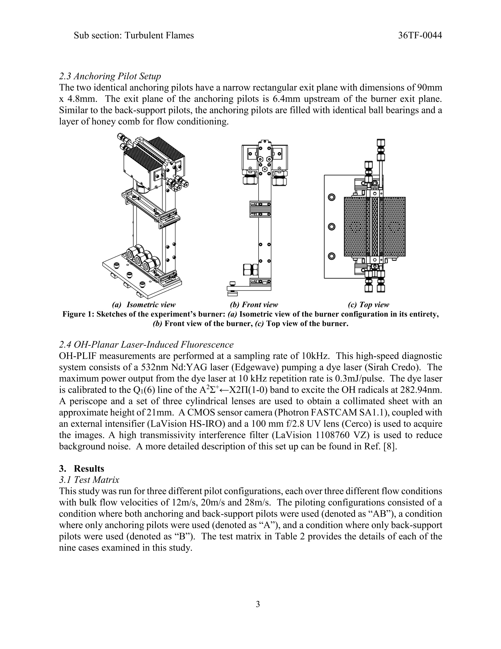
36TF-0044Sub section: Turbulent FlamesSpring Technical MeetingEastern States Section of the Combustion InstituteMarch 4-7,2018 Sub section: Turbulent Flames36TF-0044 State College, Pennsylvania The Effects of Piloting on Turbulent Flame Structure Ryan Shupp', Ankit Tyagi', Isaac Boxx’, Stephen Peluso', and JacquelineO'Connor* Mechanical and Nuclear Engineering, Pennsylvania State University, University Park, PA DLR, German Aerospace Center, Stuttgart, Germany, 70596 *Corresponding Author Email: jxo22@psu.edu Pilot flames are commonly used to study turbulent flames as they present a means of preventingblow off at higher velocities. There are open questions regarding how pilot flames affect the mainflame. This is true for both anchoring pilots, which are small pilot flames located at the base of theflame, and back-support pilots, which produce adiabatic or superadiabatic boundaries around theflame. The question of how the presence and size of pilot flames affect the properties of the mainflames is important to understanding the behavior of the main flame. The purpose of this study isto explore how the presence of pilot flames affects the flame surface density, global consumptionspeed, and flame curvature statistics of a turbulent, premixed flame over a range of velocities.Natural gas was used as a fuel and the equivalence ratio was held constant at 1. Three different pilotflame configurations were used to explore the interaction between flame and pilot, includingvariations in the presence of both the anchoring pilots and the back-support pilots. The results ofthis study will affect our interpretation of flame sheet dynamics in a range of piloted flames. Keywords: Turbulent Flames, Stabilization, Pilot Flames 1. Introduction Piloting is used in many turbulent combustion experiments to help stabilize flames at high flowvelocities and turbulence intensities. In this study, we focus on premixed flames only, as thestructure and propagation of premixed flames is canonically different than that of non-premixedor even partially premixed flames.These piloting schemes vary between experiments, buttypically can be put into two major categories: anchoring pilots, which are used to stabilize thebase of the flame and prevent blow-off in higher velocity cases, and back-support pilots, whichare used to produce an adiabatic or superadiabatic boundary layer to provide more favorableconditions for combustion. Table 1 provides examples of burners that have used pilot flames anddescribes the nature ofthe pilots used. While the use of pilot flames is very common, it’s unclear how these pilot flames change thestructure and behavior of the turbulent flames they stabilized. The goal of this study is to begin tounderstand the impact of pilot flames on turbulent premixed flame behavior. In this particularstudy, we have found that the presence of pilot flames has a negligible effect on the turbulentglobal consumption speed and flame brush thickness of turbulent premised flames. Table 1. List of experiments that utilize pilot flames to study turbulent premixed flames. Authors Type ofPilot Experimental Goal Pilot Fuel Pilot EquivalenceRatio Skiba et al. (Michigan)[1] Back- Support Study of flame structure responses to extreme levels ofturbulence Methane 0.98 Zhou et al.(Lund)[2] Back-Support Exploration of the relationshipbetween reactive scalar and jetspeed Methane 0.4 Won et al. (Princeton)[31 Anchoring Research of turbulent flamepropagation’s response to lowtemperature fuel chemistry Methane 1.00 Yuen et al.(Toronto) [4] Anchoring Characterization of flame structure in thin reactions regime Methane.Ethylene Not Provided Dunn et al.(Sydney) [5] Anchoring Studying the finite-rate chemistry effects of a premixed1et Natural Gas 1.00 Venkateswaran etal. (Georgia Tech) [6] Anchoring Understand the effects of syngasfuel blends on turbulent consumption speed Methane 0.9 Steinberg et al.(Michigan)[7] Back-Support Studying the effect of turbulence-flame interactions onflame stretch Methane Varying 2.Experimental methods 2.1 Main Burner Setup The experimental setup consists of a burner with an exit plane of dimensions 100mm x 10mm(Figure 1). The burner contains two stacked sections with heights of 178mm and 160mm. Thefirst section contains the inlet for incoming flow ofthe air-fuel mixture and a ceramic honeycomblayer. The other section contains another honeycomb layer and two perforated plates. As a meansof conditioning the flow of the air-fuel mixture (utilizing natural gas as the fuel and an equivalenceratio of 1), the flow is sent through both layers of honeycomb inside the burner prior to reachingthe exit plane of the burner. The two perforated plates are placed at 30mm and 10mm upstreamof the burner exit plane and are used to create turbulence in the flow field. The perforated plates,with a 3.175mm hole diameter and 40% open area, are able to generate a non-reacting averageflow turbulence intensity of 18% at the exit of the burner. This turbulence intensity is normalizedthrough the use of the bulk flow velocities. 2.2 Back Support Pilot Setup The two identical back-support pilots each consist of rectangular exit planes with dimensions90mm x 30mm. The exit plane of the back support pilots is 13mm upstream of the burner exitplane. The cavity of the back-support pilots is filled with ball bearings as a means of ensuring thatthat flow is relatively uniform throughout the entire rectangular pilot. 2.3 Anchoring Pilot Setup The two identical anchoring pilots have a narrow rectangular exit plane with dimensions of 90mmx 4.8mm. The exit plane of the anchoring pilots is 6.4mm upstream of the burner exit plane.Similar to the back-support pilots, the anchoring pilots are filled with identical ball bearings and alayer of honey comb for flow conditioning. (a) Isometric view (b) Front view (c) Top view Figure 1: Sketches of the experiment’s burner: (a) Isometric view of the burner configuration in its entirety,(b) Front view of the burner, (c) Top view of the burner. 2.4 OH-Planar Laser-Induced Fluorescence OH-PLIF measurements are performed at a sampling rate of 10kHz. This high-speed diagnosticsystem consists of a 532nm Nd:YAG laser (Edgewave) pumping a dye laser (Sirah Credo). Themaximum power output from the dye laser at 10 kHz repetition rate is 0.3mJ/pulse. The dye laseris calibrated to the Qi(6) line of the A22+←X2II(1-0) band to excite the OH radicals at 282.94nm.A periscope and a set of three cylindrical lenses are used to obtain a collimated sheet with anapproximate height of21mm. A CMOS sensor camera (Photron FASTCAM SA1.1), coupled withan external intensifier (LaVision HS-IRO) and a 100 mm f/2.8 UV lens (Cerco) is used to acquirethe images. A high transmissivity interference filter (LaVision 1108760 VZ) is used to reducebackground noise. A more detailed description of this set up can be found in Ref. [8]. 3. Results 3.1 Test Matrix This study was run for three different pilot configurations, each over three different flow conditionswith bulk flow velocities of 12m/s, 20m/s and 28m/s. The piloting configurations consisted of acondition where both anchoring and back-support pilots were used (denoted as“AB”), a conditionwhere only anchoring pilots were used (denoted as “A”), and a condition where only back-supportpilots were used (denoted as “B"). The test matrix in Table 2 provides the details of each of thenine cases examined in this study. Table 2. Test matrix including variations in the bulk flow velocities, the Reynolds number based onthe hydraulic diameter, and the pilot configuration for each case. CaseNumber EquivalenceRatio (@) BulkFlowVelocity Um/s ReynoldsNumber(HydraulicDiameter) Pilot Configuration u'[m/s] 12AB 1.0 12 15485 All 2.0 12A 1.0 12 15485 Anchoring 2.0 12B 1.0 12 15485 Back-support 2.0 20AB 1.0 20 25808 All 3.2 20A 1.0 20 25808 Anchoring 3.2 20B 1.0 20 25808 Back-support 3.2 20AB 1.0 28 36131 All 4.5 20A 1.0 28 36131 Anchoring 4.5 20B 1.0 28 36131 Back-support 4.5 3.2 Progress Variables Figure 2 shows the stitched, time-averaged progress variables with red lines used to denote thethree fields of view used for data collection, and Figure 3 shows an instantaneous LIF image ofthe flames in the first field of view. From the progress variable plots, there are no observabledifferences between the different pilot configurations as the time averaging diminishes anyinstantaneous topological differences that may exist in the flame structure. The instantaneous LIFviews show the benefits that back-support pilots have on data collection. In the absence of back-support pilots, the absence of the additional OH around the flame makes edge detection andcurvature calculations difficult and leads to a degree of ambiguity in regards to the behavior of thestructure of the flame. Figure 2: Stitched, time-averagedprogress variable plots for each of the 9cases. Figure 3: Instantaneous LIF images of the first field of view foreach of the 9 cases. 3.3 Flame Brush Thickness By taking an average of the instantaneous binarized images from the experiment, time-averagedprogress variables (C) were found and used as a means of calculating the flame brush thicknesses.According to studies conducted by Kheirkhah et al. [9] and Namazian et al. [10], the magnitudeof the flame brush thickness can be approximated through the use of the maximum gradient of theprogress variable in the cross-stream direction, as in Eq. 1. Figure 4 provides the plots of the flame brush thicknesses for each of the velocities versusdownstream position. The results show that at each of the velocities tested, the presence or absenceof pilot flames had little to no effect on the slope of the flame brush thickness plot. Figure 4: Flame brush thickness vs. position for bulk flow velocities of (a) 12m/s,(b) 20m/s and (c) 28m/s. 3.4 Turbulent Global Consumption Speed The turbulent global consumption speed can be calculated in the equation that follows, where thetotal reactant mass flow rate is divided by the product of the reactant gas density and the surfacearea of a contour for a given progress variable, as in Eq. 2. Figure 5: Turbulent global consumption speeds for progress variables of (a) 0.1, (b) 0.2 and (c) 0.3. We have utilized three different values of progress variables to calculate global consumption speed(c= 0.1,0.2,0.3). The density of the reactants is taken at 300K. As we increase the bulk flowvelocity, the turbulence intensity also increases and the global consumption speeds increase. Conversely, as the progress variables increase, global consumption speeds decrease. This is dueto the fact that larger progress variables result in a larger averaged surface area of the flame, asshown in Figure 5. As shown in the plots, there is virtually no difference in the global consumptionspeeds of flames when subjected to the various pilot flame configurations. 4. Conclusions In summary, the overarching implication of this initial work is that any potential effects that pilotflames could have on the global behavior of turbulent flames can be regarded as negligible. Theslope of the flame brush thickness data appeared to be consistent across each of the pilot conditionsand was merely a function of bulk flow velocity. Furthermore, the global consumption speeds ofthe turbulent flames were likewise unaffected by the pilots, and were affected only by the bulkflow velocity and the progress variable. With pilot flames being a resource so frequently used inthe combustion community, it is essential to ensure that data has not been skewed as a result. Inthe future, the authors will continue to explore potential effects that pilots may have on the localbehavior of these flames. In particular, we will consider the impact of piloting on flame wrinklingand the frequency of flame interaction events and flame hole formation. Acknowledgements Thiss work was supported by the Air Force Office of Scientific Research under GrantFA9550-16-1-0075 with program manager Dr. Chiping Li. The authors gratefully acknowledgeDr. Campbell Carter at the AFRL and LaVision GmbH for their advice and loan of equipmentduring these experiments. References 1. Skiba, A.W., et al., Premixed flames subjected to extreme levels ofturbulence part I: Flamestructure and a new measured regime diagram. Combustion and Flame, 2017. 2. Zhou, B., et al., Distributed reactions in highly turbulent premixed methane/air flames:Part I. Flame structure characterization. Combustion and Flame, 2015.162(7): p.2937-2953. 3. Won, S.H., et al., The role of low temperature fuel chemistry on turbulent flamepropagation. Combustion and Flame,2014.161(2):p. 475-483. 4. Yuen, F.T. and O.L. Gulder, Premixed turbulent flame front structure investigation byRayleigh scattering in the thin reaction zone regime. Proceedings of the CombustionInstitute,2009.32(2):p. 1747-1754. 5. Dunn, M.J., A.R. Masri, and R.W. Bilger, A new piloted premixed jet burner to study strongfinite-rate chemistry effects. Combustion and Flame, 2007.151(1): p. 46-60. 6. Venkateswaran, P., Measurements and modeling of turbulent consumption speeds ofsyngas fuel blends. 2013, Georgia Institute of Technology. 7. Steinberg, A.M., The dynamics ofturbulent premixed flames: Mechanisms and models forturbulence-flame interaction. 2009, University of Michigan. 8. Tyagi, A., et al. Structure of Flames in Flame Interaction Zones. in 2018 AIAA AerospaceSciences Meeting. 2018. 9. Kheirkhah, S. and O. Giilder, Topology and brush thickness of turbulent premixed V-shaped flames. Flow, turbulence and combustion, 2014.93(3): p. 439-459. 10. Namazian, M., L. Talbot, and F. Robben. Density fluctuations in premixed turbulentflames. in Symposium (International) on Combustion.1985. Elsevier. Pilot flames are commonly used to study turbulent flames as they present a means of preventing blow off at higher velocities. There are open questions regarding how pilot flames affect the main flame. This is true for both anchoring pilots, which are small pilot flames located at the base of the flame, and back-support pilots, which produce adiabatic or superadiabatic boundaries around the flame. The question of how the presence and size of pilot flames affect the properties of the main flames is important to understanding the behavior of the main flame. The purpose of this study is to explore how the presence of pilot flames affects the flame surface density, global consumption speed, and flame curvature statistics of a turbulent, premixed flame over a range of velocities. Natural gas was used as a fuel and the equivalence ratio was held constant at 1. Three different pilot flame configurations were used to explore the interaction between flame and pilot, including variations in the presence of both the anchoring pilots and the back-support pilots. The results of this study will affect our interpretation of flame sheet dynamics in a range of piloted flames.
确定


还剩4页未读,是否继续阅读?

产品配置单


北京欧兰科技发展有限公司为您提供《湍流火焰中时间分辨OH平面激光诱导荧光PLIF检测方案(CCD相机)》,该方案主要用于煤炭中时间分辨OH平面激光诱导荧光PLIF检测,参考标准--,《湍流火焰中时间分辨OH平面激光诱导荧光PLIF检测方案(CCD相机)》用到的仪器有LaVision IRO 图像增强器、PLIF平面激光诱导荧光火焰燃烧检测系统、德国LaVision PIV/PLIF粒子成像测速场仪、LaVision DaVis 智能成像软件平台
推荐专场
CCD相机/影像CCD
更多


相关方案
更多
该厂商其他方案
更多