


方案详情
文
使用英国Litron公司Nano T 135-15 PIV型激光器做光源,用LaVision imager intense相机做成像器件,对1立方分米尺寸正方体内纳米流体的湍流和自然对流流动进行了测量,获得了重要的流场速度场结果。
方案详情

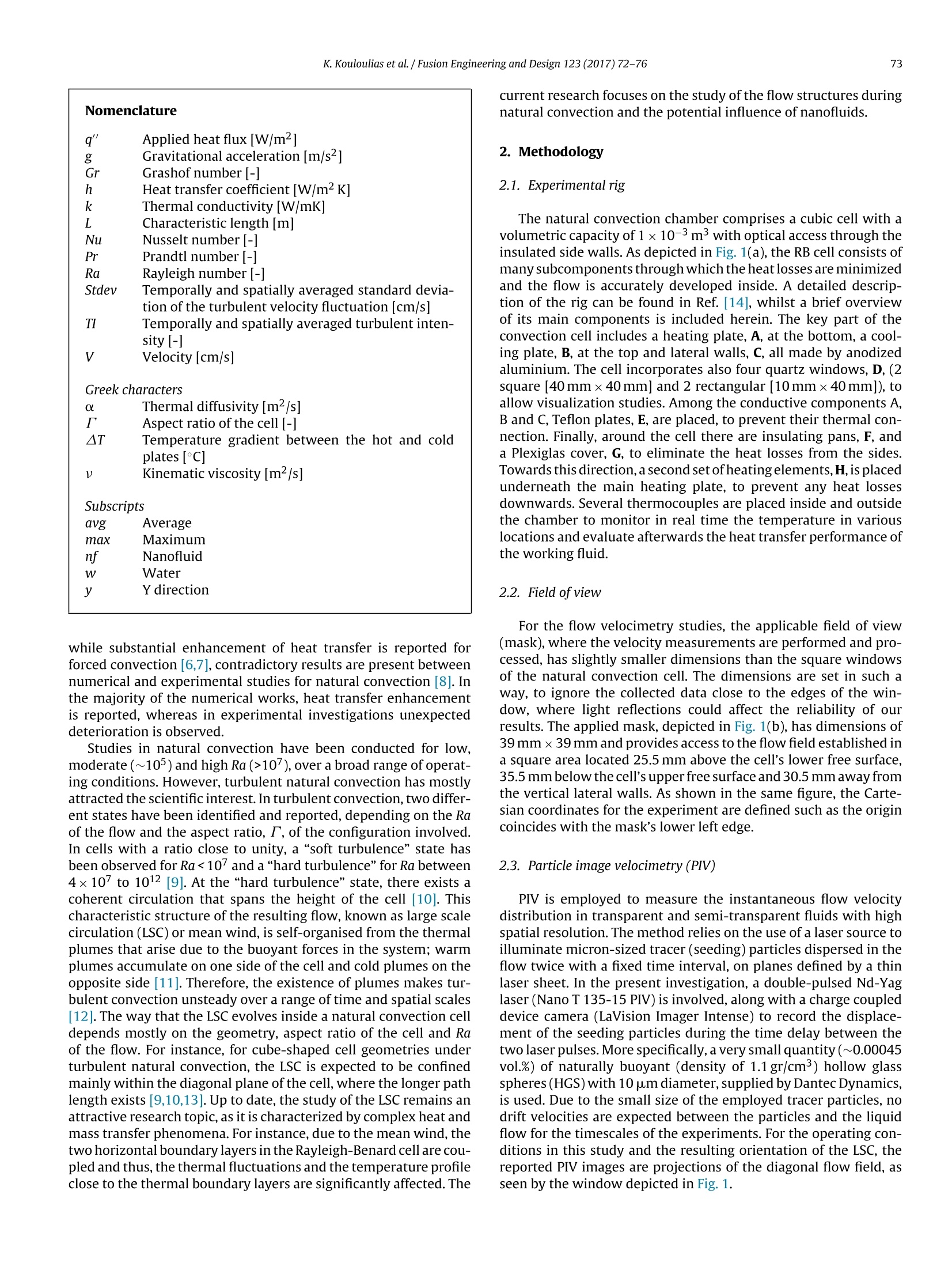
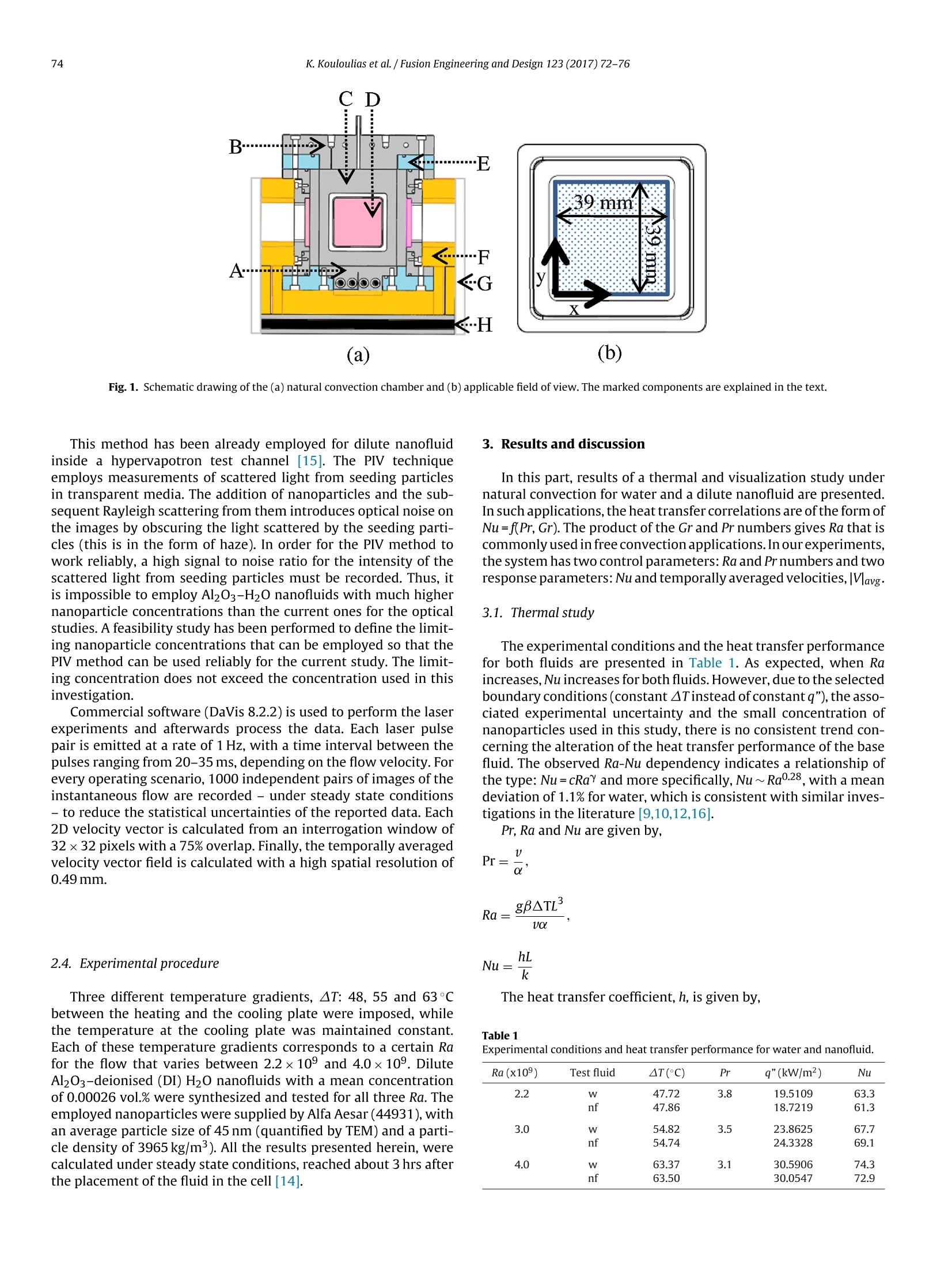
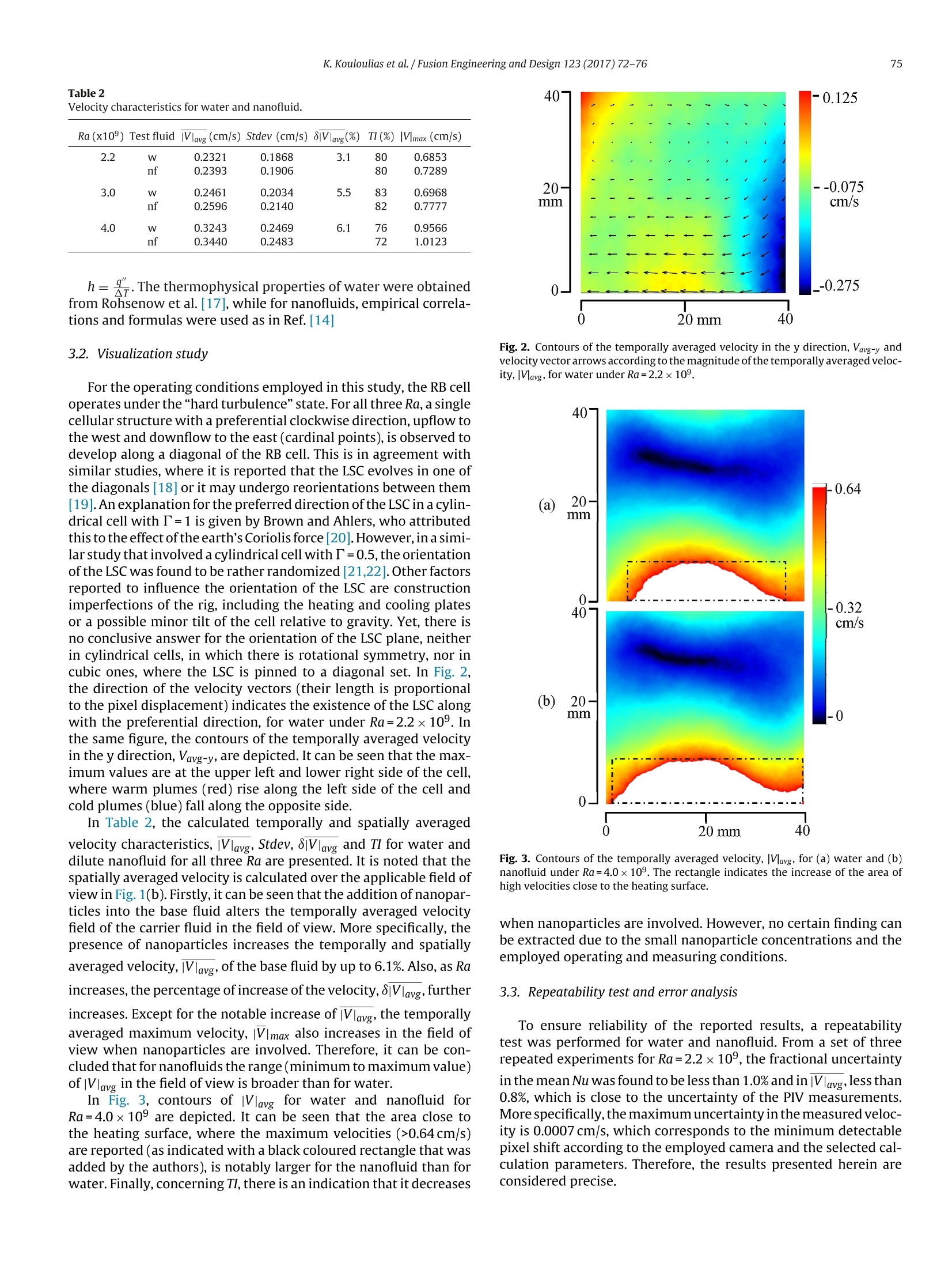
Fusion Engineering and Design 123 (2017)72-76 73K. Kouloulias et al. / Fusion Engineering and Design 123 (2017)72-76 http://dx.doi.org/10.1016/j.fusengdes.2017.05.120 Contents lists available at ScienceDirect Fusion Engineering and Design journal homepage:www.elsevier.com/locate/fusengdes Measurement of flow velocity during turbulent natural convection innanofluids K. Kouloulias a,*, A. Sergis,Y. Hardalupas,T.R. Barrett a Imperial College London, Mechanical Engineering Department, London SW7 2AZ, UKD CCFE, Culham Science Centre, Abingdon, Oxon OX14 3DB, UK HIGHLIGHTS · As Ra increases, Vlavg and |V max for both water and nanofluid increase. ·|V max for nanofluids is higher than for water in the field of view. · lVlavg for nanofluids is up to 6.1% higher than for water in the field of view. · The addition of Al2O3 nanoparticles alters the mass transfer behavior of water. ARTIC L EIN F O ABSTRACT Article history: Received 30 September 2016Received in revised form 11 May 2017Accepted 25 May 2017 Available online 10 June 2017 Keywords: Turbulent natural convection Rayleigh-Benard NanofluidsParticle image velocimetryCooling Increased cooling performance is eagerly required for many cutting edge engineering and industrial tech-nologies. Nanofluids have attracted considerable interest due to their potential to enhance the thermalperformance of conventional heat transfer fluids. However,heat transfer in nanofluids is a controversialresearch theme, since there is yet no conclusive answer to explain the underlying heat transfer mech-anisms. This study investigates the physics behind the heat transfer behavior of Al2O3-H20 nanofluidsunder natural convection. A high spatial resolution flow velocimetry method -Particle Image Velocime-try- is employed in dilute nanofluids inside a Rayleigh-Benard configuration with appropriate opticalaccess. The resulting mean velocity and flow structures of pure water and nanofluids are reported andtheir overall heat transfer performances are compared for Rayleigh numbers,Ra, of the order of 10°. Thispaper aims to identify the contribution of the suspended nanoparticles on the heat and mass transfermechanisms in low flow velocity applications, as those occurring during natural convection. The outcomeof this work is a first step towards the evaluation of the applicability of nanofluids in applications wheremore complex heat transfer modes, namely boiling and Critical Heat Flux, are involved that are of greatimportance for the cooling of Fusion reactors. Fusion C 2017 The Authors. Published by Elsevier B.V. This is an open access article under the CC BY license 1. Introduction Natural convection is a ubiquitous heat transfer mode in naturebut also in numerous engineering applications where both laminarand turbulent flows are established.Rayleigh-Benard(RB) convec-tion is one of the most established models to study the associatedheat and mass transport mechanisms, on the basis of the simplicityand controllability it offers. In the majority of these studies, tradi-tional heat transfer fluids, such as air and water, are considered asworking fluids.However, with the emergence of nanotechnology ( * Corresponding author. ) and the development of a new category of coolants, called nanoflu-ids, the interest in free and natural convection flow problems hasbeen re-established[1,2]. Nanofluids are a new class of heat transfer fluids engineeredby dispersing and stably suspending nanoparticles of the orderof 1-100 nm in traditional heat transfer fluids (base fluids) [3]. Asmall amount of these nano-sized particles can provide a promisingimprovement in the thermal properties of the base fluid [4]. Basedon a statistical analysis of data available in the literature, nanoflu-ids offer an enhancement of 5-9% for the conductive heat transfermode, 10-14% for the mixed conductive/convective, 40-44% forpool boiling and up to 200% for critical heat flux [5]. However, pureconvection in nanofluids is considered to be a controversial heattransfer mode in terms of heat transfer performance. For instance, ( 0920-3796/O 2017 The Authors. Published by E lsevier B.V. This is an open access article under the CC BY license ( http://creativecommons.org/licenses/b y /4.0/) . ) Nomenclature q' Applied heat flux [W/m²] g Gravitational acceleration [m/s-] Gr Grashof number [-] h Heat transfer coefficient [W/m²K] k Thermal conductivity[W/mK] L Characteristic length [m] Nu Nusselt number-| Pr Prandtl number [-1 Ra Rayleigh number [-] Stdev Temporally and spatially averaged standard devia- tion of the turbulent velocity fluctuation [cm/s] TI Temporally and spatially averaged turbulent inten- sity [-] v Velocity [cm/s] Greek characters Thermal diffusivity [m-/s] AT Aspect ratio of the cell [-] Temperature gradient between the hot and cold plates [°C] Kinematic viscosity[m²/s] Subscripts avg Average max Maximum nf Nanofluid Water y Y direction while substantial enhancement of heat transfer is reported forforced convection [6,7], contradictory results are present betweennumerical and experimental studies for natural convection [8]. Inthe majority of the numerical works, heat transfer enhancementis reported, whereas in experimental investigations unexpecteddeterioration is observed. Studies in natural convection have been conducted for low,moderate (~105) and high Ra (>107), over a broad range of operat-ing conditions. However, turbulent natural convection has mostlyattracted the scientific interest. In turbulent convection, two differ-ent states have been identified and reported, depending on the Raof the flow and the aspect ratio, T, of the configuration involved.In cells with a ratio close to unity, a “soft turbulence”state hasbeen observed for Ra<10 and a"hard turbulence” for Ra between4x107 to 1012 [9]. At the “hard turbulence”state, there exists acoherent circulation that spans the height of the cell [10]. Thischaracteristic structure of the resulting flow, known as large scalecirculation (LSC) or mean wind, is self-organised from the thermalplumes that arise due to the buoyant forces in the system; warmplumes accumulate on one side of the cell and cold plumes on theopposite side [11]. Therefore, the existence of plumes makes tur-bulent convection unsteady over a range of time and spatial scales[12]. The way that the LSC evolves inside a natural convection celldepends mostly on the geometry, aspect ratio of the cell and Raof the flow. For instance, for cube-shaped cell geometries underturbulent natural convection, the LSC is expected to be confinedmainly within the diagonal plane of the cell, where the longer pathlength exists [9,10,13]. Up to date, the study of the LSC remains anattractive research topic, as it is characterized by complex heat andmass transfer phenomena. For instance, due to the mean wind, thetwo horizontal boundary layers in the Rayleigh-Benard cell are cou-pled and thus, the thermal fluctuations and the temperature profileclose to the thermal boundary layers are significantly affected. The current research focuses on the study of the flow structures duringnatural convection and the potential influence of nanofluids. 2. Methodology 2.1. Experimental rig The natural convection chamber comprises a cubic cell with avolumetric capacity of 1×10⁻³m3 with optical access through theinsulated side walls. As depicted in Fig. 1(a), the RB cell consists ofmany subcomponents through which the heat losses are minimizedand the flow is accurately developed inside. A detailed descrip-tion of the rig can be found in Ref.[14], whilst a brief overviewof its main components is included herein. The key part of theconvection cell includes a heating plate, A, at the bottom, a cool-ing plate, B, at the top and lateral walls, C, all made by anodizedaluminium. The cell incorporates also four quartz windows, D, (2square [40 mmx40 mm] and 2 rectangular [10mmx40mm]), toallow visualization studies. Among the conductive components A,Band C, Teflon plates, E, are placed, to prevent their thermal con-nection. Finally, around the cell there are insulating pans, F, anda Plexiglas cover, G, to eliminate the heat losses from the sides.Towards this direction, a second setofheating elements,H, is placedunderneath the main heating plate, to prevent any heat lossesdownwards. Several thermocouples are placed inside and outsidethe chamber to monitor in real time the temperature in variouslocations and evaluate afterwards the heat transfer performance ofthe working fluid. 2.2. Field ofview For the flow velocimetry studies, the applicable field of view(mask), where the velocity measurements are performed and pro-cessed, has slightly smaller dimensions than the square windowsof the natural convection cell. The dimensions are set in such away, to ignore the collected data close to the edges of the win-dow, where light reflections could affect the reliability of ourresults. The applied mask, depicted in Fig. 1(b),has dimensions of39 mmx39 mm and provides access to the flow field established ina square area located 25.5 mm above the cell's lower free surface,35.5 mm below the cell's upper free surface and 30.5 mm away fromthe vertical lateral walls.As shown in the same figure, the Carte-sian coordinates for the experiment are defined such as the origincoincides with the mask’s lower left edge. 2.3. Particle image velocimetry (PIV) PIV is employed to measure the instantaneous flow velocitydistribution in transparent and semi-transparent fluids with highspatial resolution. The method relies on the use of a laser source toilluminate micron-sized tracer (seeding) particles dispersed in theflow twice with a fixed time interval, on planes defined by a thinlaser sheet. In the present investigation, a double-pulsed Nd-Yaglaser (Nano T135-15 PIV) is involved,along with a charge coupleddevice camera (LaVision Imager Intense) to record the displace-ment of the seeding particles during the time delay between thetwo laser pulses. More specifically, a very small quantity(~0.00045vol.%) of naturally buoyant (density of 1.1 gr/cm) hollow glassspheres (HGS)with 10 um diameter, supplied by Dantec Dynamics,is used. Due to the small size of the employed tracer particles, nodrift velocities are expected between the particles and the liquidflow for the timescales of the experiments. For the operating con-ditions in this study and the resulting orientation of the LSC, thereported PIV images are projections of the diagonal flow field, asseen by the window depicted in Fig. 1. (a) (b) Fig. 1. Schematic drawing of the (a) natural convection chamber and (b) applicable field of view. The marked components are explained in the text. This method has been already employed for dilute nanofluidinside a hypervapotron test channel [15]. The PIV techniqueemploys measurements of scattered light from seeding particlesin transparent media. The addition of nanoparticles and the sub-sequent Rayleigh scattering from them introduces optical noise onthe images by obscuring the light scattered by the seeding parti-cles (this is in the form of haze). In order for the PIV method towork reliably, a high signal to noise ratio for the intensity of thescattered light from seeding particles must be recorded. Thus, itis impossible to employ Al203-H20 nanofluids with much highernanoparticle concentrations than the current ones for the opticalstudies. A feasibility study has been performed to define the limit-ing nanoparticle concentrations that can be employed so that thePIV method can be used reliably for the current study. The limit-ing concentration does not exceed the concentration used in thisinvestigation. Commercial software (DaVis 8.2.2) is used to perform the laserexperiments and afterwards process the data. Each laser pulsepair is emitted at a rate of 1 Hz, with a time interval between thepulses ranging from 20-35 ms, depending on the flow velocity. Forevery operating scenario, 1000 independent pairs of images of theinstantaneous flow are recorded -under steady state conditions-to reduce the statistical uncertainties of the reported data. Each2D velocity vector is calculated from an interrogation window of32×32 pixels with a 75% overlap. Finally, the temporally averagedvelocity vector field is calculated with a high spatial resolution of0.49mm. 2.4. Experimental procedure Three different temperature gradients, AT: 48,55 and 63℃between the heating and the cooling plate were imposed, whilethe temperature at the cooling plate was maintained constant.Each of these temperature gradients corresponds to a certain Rafor the flow that varies between 2.2×10° and 4.0x10⁹.DiluteAl2O3-deionised (DI) H20 nanofluids with a mean concentrationof 0.00026 vol.% were synthesized and tested for all three Ra. Theemployed nanoparticles were supplied by Alfa Aesar (44931), withan average particle size of 45 nm (quantified by TEM) and a parti-cle density of 3965 kg/m). All the results presented herein, werecalculated under steady state conditions, reached about 3 hrs afterthe placement of the fluid in the cell [14]. 3. Results and discussion In this part, results of a thermal and visualization study undernatural convection for water and a dilute nanofluid are presented.In such applications, the heat transfer correlations are of the form ofNu=f(Pr,Gr). The product of the Gr and Pr numbers gives Ra that iscommonly used in free convection applications. In ourexperiments,the system has two control parameters: Ra and Pr numbers and tworesponse parameters: Nu and temporallyaveraged velocities, Vlavg. 3.1. Thermal study The experimental conditions and the heat transfer performancefor both fluids are presented in Table 1. As expected, when Raincreases,Nu increases for both fluids. However, due to the selectedboundary conditions (constant ATinstead of constant q"),the asso-ciated experimental uncertainty and the small concentration ofnanoparticles used in this study, there is no consistent trend con-cerning the alteration of the heat transfer performance of the basefluid. The observed Ra-Nu dependency indicates a relationship ofthe type: Nu=cRay and more specifically, Nu~ Ra0.28, with a meandeviation of 1.1% for water, which is consistent with similar inves-tigations in the literature [9,10,12,16]. Pr, Ra and Nu are given by, 凡Nu=一k The heat transfer coefficient, h, is given by, Table1 Experimental conditions and heat transfer performance for water and nanofluid. Ra (x10°) Test fluid AT(C) Pr q"(kW/m²) Nu 2.2 W 47.72 3.8 19.5109 63.3 nf 47.86 18.7219 61.3 3.0 W 54.82 3.5 23.8625 67.7 nf 54.74 24.3328 69.1 4.0 W 63.37 3.1 30.5906 74.3 nf 63.50 30.0547 72.9 Table 2Velocity characteristics for water and nanofluid. Ra (x109) Test fluid Ilavg (cm/s) Stdev (cm/s) 8|Vlavg(%) TI(%) Vlmax (cm/s) 2.2 W 0.2321 0.1868 3.1 80 0.6853 nf 0.2393 0.1906 80 0.7289 3.0 W 0.2461 0.2034 5.5 83 0.6968 nf 0.2596 0.2140 82 0.7777 4.0 0.3243 0.2469 6.1 76 0.9566 nf 0.3440 0.2483 72 1.0123 h=. The thermophysical properties of water were obtainedfrom Rohsenow et al.[17],while for nanofluids, empirical correla-tions and formulas were used as in Ref.[14] 3.2. Visualization study For the operating conditions employed in this study, the RB celloperates under the“hard turbulence"state. For all three Ra, a singlecellular structure with a preferential clockwise direction, upflow tothe west and downflow to the east (cardinal points), is observed todevelop along a diagonal of the RB cell. This is in agreement withsimilar studies, where it is reported that the LSC evolves in one ofthe diagonals [18] or it may undergo reorientations between them[19]. An explanation for the preferred direction of the LSC in a cylin-drical cell with T=1 is given by Brown and Ahlers, who attributedthis to the effect ofthe earth’s Coriolis force [20]. However, in a simi-lar study that involved a cylindrical cell with T=0.5,the orientationof the LSC was found to be rather randomized [21,22].Other factorsreported to influence the orientation of the LSC are constructionimperfections of the rig, including the heating and cooling platesor a possible minor tilt of the cell relative to gravity. Yet, there isno conclusive answer for the orientation of the LSC plane, neitherin cylindrical cells, in which there is rotational symmetry, nor incubic ones, where the LSC is pinned to a diagonal set. In Fig. 2,the direction of the velocity vectors (their length is proportionalto the pixel displacement) indicates the existence of the LSC alongwith the preferential direction, for water under Ra=2.2×10⁹. Inthe same figure, the contours of the temporally averaged velocityin the y direction, Vavg-y, are depicted. It can be seen that the max-imum values are at the upper left and lower right side of the cell,where warm plumes (red) rise along the left side of the cell andcold plumes (blue) fall along the opposite side. In Table 2, the calculated temporally and spatially averaged velocity characteristics, iVlavg, Stdev, 8Vlavg and TI for water anddilute nanofluid for all three Ra are presented. It is noted that thespatially averaged velocity is calculated over the applicable field ofview in Fig. 1(b). Firstly, it can be seen that the addition ofnanopar-ticles into the base fluid alters the temporally averaged velocityfield of the carrier fluid in the field of view. More specifically, thepresence of nanoparticles increases the temporally and spatiallyaveraged velocity,IVlavg, of the base fluid by up to 6.1%. Also, as Raincreases, the percentage of increase of the velocity,8|Vlavg, furtherincreases. Except for the notable increase of |Vlavg, the temporallyaveraged maximum velocity, |Vlmax also increases in the field ofview when nanoparticles are involved. Therefore, it can be con-cluded that for nanofluids the range (minimum to maximum value)of |Vlavg in the field of view is broader than for water. In Fig. 3, contours of |Vlavg for water and nanofluid forRa=4.0×10° are depicted. It can be seen that the area close tothe heating surface, where the maximum velocities (>0.64 cm/s)are reported (as indicated with a black coloured rectangle that wasadded by the authors), is notably larger for the nanofluid than forwater. Finally, concerning TI, there is an indication that it decreases Fig. 2. Contours of the temporally averaged velocity in the y direction, Vavg-y andvelocity vector arrows according to the magnitude of the temporally averaged veloc-ity, lavg, for water under Ra=2.2×10°. Fig. 3. Contours of the temporally averaged velocity, lVlavg, for (a) water and (b)nanofluid under Ra=4.0x10°. The rectangle indicates the increase of the area ofhigh velocities close to the heating surface. when nanoparticles are involved. However, no certain finding canbe extracted due to the small nanoparticle concentrations and theemployed operating and measuring conditions. 3.3. Repeatability test and error analysis To ensure reliability of the reported results, a repeatabilitytest was performed for water and nanofluid. From a set of threerepeated experiments for Ra=2.2×10°, the fractional uncertaintyin the mean Nu was found to be less than 1.0% and in |Vlavg,less than0.8%, which is close to the uncertainty of the PIV measurements.More specifically, the maximum uncertainty in the measured veloc-ity is 0.0007 cm/s, which corresponds to the minimum detectablepixel shift according to the employed camera and the selected cal-culation parameters. Therefore, the results presented herein areconsidered precise. This study examines experimentally the heat and mass transfer characteristics of a dilute Al203-DIH2O nanofluid under turbulentnatural convection. Heat transfer measurements simultaneouslywith a high spatial resolution velocimetry method (PIV) wereobtained in a Rayleigh-Benard cell with optical access. Firstly, as Raincreases |Vlavg and|Vmax, consistently increase for both test fluids.Interesting enough, both velocities for nanofluids are higher thanfor water in the field of view. Therefore, we report that the additionof a small amount of Al203 nanoparticles, 0.00026 vol.% to DI wateralters the mass transfer behavior of the base fluid significantly(more than 6% increase of |Vlavg in the field of view). Concerningthe effect ofthe suspended nanoparticles on the heat transfer per-formance of the base fluid, there is no consistent trend. However,in a past experimental study of the authors [14] the thermal per-formance of Al203-DI H20 nanofluids with concentrations up to0.12 vol.% is reported. In the literature, the majority of the relevantresearch considers constant q”instead of constant AT between thehot and cold plates of the RB cell. In two highly cited articles [12,23]a comparison is performed between the results obtained underthese two operating conditions. The outcome is that for Ra~109the heat transport in the two cases is essentially the same. Thiswork is a step towards the understanding of the contribution of thenanoparticles on the heat and mass transfer mechanisms in lowflow velocity applications, such as natural convection. Acknowledgments This work was funded by the RCUK Energy Program andEURATOM. We are grateful to CCFE for the financial support throughtheCASE EPSRC studentship. We would like to thank Dr. Byon Chanfor his valuable help in designing and manufacturing the thermalrig. Data supporting this publication can be obtained by requestfrom MultiphaseFlows@imperial.ac.uk. The views and opinionsexpressed herein do not necessarily reflect those of the EuropeanCommission. ( References ) [2] I.Rashidi, O.Mahian, G. Lorenzini, C. Biserni, S. Wongwises, Naturalconvection of Al203/water nanofluid in a square cavity: effects ofheterogeneous heating, Int. J. Heat Mass Transfer 74 (2014)391-402. [3] S.U.S. Choi, Nanofluids: from vision to reality through research,J. HeatTransfer 131 (3)(2009)1-9. ( [ 4 ] S. Rash i d i , M. Bovan d, J . A. Esfaha n i, G . Ahmadi, Discrete par t icle model f o r c onvective AL203-wa t er nanofluid around a tr i a n gular obst a cle, App l . Therm. E n g. 1 00(2016)39- 5 4 . ) ( [ 5] A . Se r g is, Y. Harda lu pas, Anom a lous heat tr a nsfer m o d es of nanofluids: a review b a sed on statist i cal analysis,Nanoscale R es. Lett. 6(1)(2011), 391-391. ) ( [ 6] Y . Xuan, Q. L i , I n vestigation on convective he a t transfer a n d f l ow features of n an o fluids , J. Heat Transfer 1 25 (1)(20 0 3 )15 1. ) ( [7] S S . K akac, A. Pramuanj a roenkij , R eview of c onvective heat t ransfer enh a ncemen t with n ano f lui d s , I nt. J. Hea t Mass T ran s f er 52 (13-14)(2009) 3 187-3196. ) ( [8] S. Savithiri, A . P attamatt a , S.K. Das, A single-co m ponen t non h omogeneous l att i ce bo l tzmann model fo r n a tural c o nv e ction in A l 203/water nan o fluid, Numer. H e at Transfer Part A : Appl.68(10)(2015 ) 11 06 - 1 1 2 4. ) [9]G. Zocchi, E. Moses,A. Libchaber, Coherent structures in turbulent convection,an experimental study,Physica A 166(3)(1990)387-407. ( [10 X ] .L.Qiu, K.Q. X ia, Viscous b oundar y lay e r s at t h e s i dewall o f a con v ection cel l , P hys. Rev. E 58(1)(1998)486-491. ) [11] X.L. Qiu, P. Tong, Temperature oscillations in turbulent Rayleigh-Benardconvection, Phys. Rev. E 66 (2 Pt 2)(2002)026308. [12]R. Verzicco,K.R. Sreenivasan, A comparison of turbulent thermal convectionbetween conditions of constant temperature and constant heat flux, J. FluidMech. 595 (2008)203-219. [13] K.-Q. Xia, C. Sun, S.-Q. Zhou, Particle image velocimetry measurement of thevelocity field in turbulent thermal convection, Phys.Rev.E 68(6)(2003)1-18. [14] K. Kouloulias,A. Sergis, Y. Hardalupas, Sedimentation in nanofluids during anatural convection experiment, Int. J. Heat Mass Transfer 101 (2016)1193-1203. [15]A. Sergis, Y. Hardalupas, T.R. Barrett, Potential for improvement in high heatflux HyperVapotron element performance using nanofluids, Nucl. Fusion 53(11)(2013)113019. ( [ 1 6] S . Ci l iberto, S. Cio n i , C. Laroche, La r ge-sca le f l ow p roperties o f t u r bulent th e rmal convection, Phys. Rev. E 5 4 (6)(1996)R5901- R 5904. ) ( [17] W.M. R oh s enow, J.P. H a rtnett, Y . I. Cho, Handbook of HEAT TRANSFER, thirded. , McGraw-Hi l l , New York, 1 9 98. ) ( [ 1 8] N . Foroozani , J J . Niemela, V. Armeni o , K . R . Sreenivasan, I n flu e nce of contai n er s hap e on s c ali n g o f tu rbulent f l uctuat i ons in conv e ction, P h ys. Re v .E 90 (6) (2014) 0 63003. ) ( [19] N . Foroozani , J.J . Niemela, V. Ar m eni o , K .R. Sreenivasa n ,Reor i ent a tions of the l arge- s cale flow in t u rb u lent co nvecti o n i n a cube, P hys. Rev. E 95 ( 3 - 1) (2017)033107. ) ( [20] E . B rown, G . A h lers, E f fect o f t h e Eart h 's Coriolis force o n t h e large-scalecirc u lation of t u rb ulen t R ayleigh - B e nard convection, Ph y s. Flu i ds 18 (12) (2006 ) 125108. ) [21]H.D.Xi, K.Q. Xia,Azimuthal motion, reorientation, cessation, and reversal ofthe large-scale circulation in turbulent thermal convection: a comparativestudy in aspect ratio one and one-half geometries, Phys. Rev. E 78 (2008)036326. [22] S. Weiss, G. Ahlers, Effect of tilting on turbulent convection: cylindricalsamples with aspect ratio (=0.50, J. Fluid Mech. 715 (2013)314-334. ( [23] 1 H . J o hn ston, C.R. Doeri ng , A com pa rison o f t u rbule n t thermal convec t ion b etween conditions of constant te m per a ture and constant flux, P hy s . Re v . Lett . 102(6) ( 2009)064501. ) tIncreased cooling performance is eagerly required for many cutting edge engineering and industrial tech-nologies. Nanofluids have attracted considerable interest due to their potential to enhance the thermalperformance of conventional heat transfer fluids. However, heat transfer in nanofluids is a controversialresearch theme, since there is yet no conclusive answer to explain the underlying heat transfer mech-anisms. This study investigates the physics behind the heat transfer behavior of Al2O3–H2O nanofluidsunder natural convection. A high spatial resolution flow velocimetry method – Particle Image Velocime-try – is employed in dilute nanofluids inside a Rayleigh-Benard configuration with appropriate opticalaccess. The resulting mean velocity and flow structures of pure water and nanofluids are reported andtheir overall heat transfer performances are compared for Rayleigh numbers, Ra, of the order of 109. Thispaper aims to identify the contribution of the suspended nanoparticles on the heat and mass transfermechanisms in low flow velocity applications, as those occurring during natural convection. The outcomeof this work is a first step towards the evaluation of the applicability of nanofluids in applications wheremore complex heat transfer modes, namely boiling and Critical Heat Flux, are involved that are of greatimportance for the cooling of Fusion reactors.
确定
还剩3页未读,是否继续阅读?

产品配置单


北京欧兰科技发展有限公司为您提供《纳米流体中湍流和自然对流流场的速度场检测方案(粒子图像测速)》,该方案主要用于其他中湍流和自然对流流场的速度场检测,参考标准--,《纳米流体中湍流和自然对流流场的速度场检测方案(粒子图像测速)》用到的仪器有德国LaVision PIV/PLIF粒子成像测速场仪、LaVision DaVis 智能成像软件平台
推荐专场


相关方案
更多
该厂商其他方案
更多