


采用Ekspla UAB 公司特别设计的半导体泵浦的固体Nd:YAG皮秒激光器,构建了一套平均功率5瓦,载波包络相位(carrier envelope phase, CEP)稳定的,光学参量啁秋放大器系统,可输出5.5TW峰值功率,重复频率1kHz。
方案详情

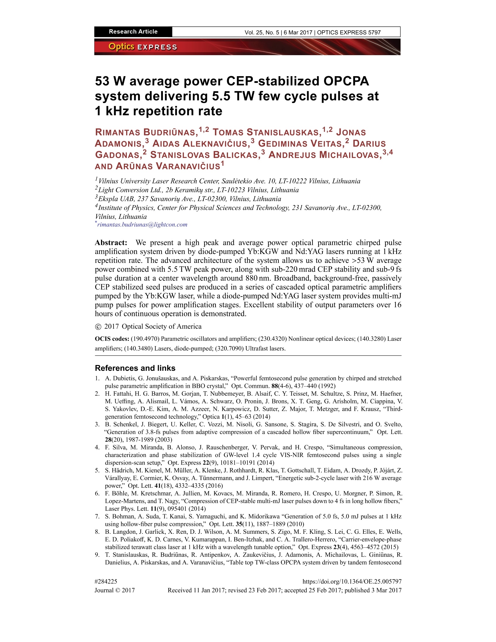
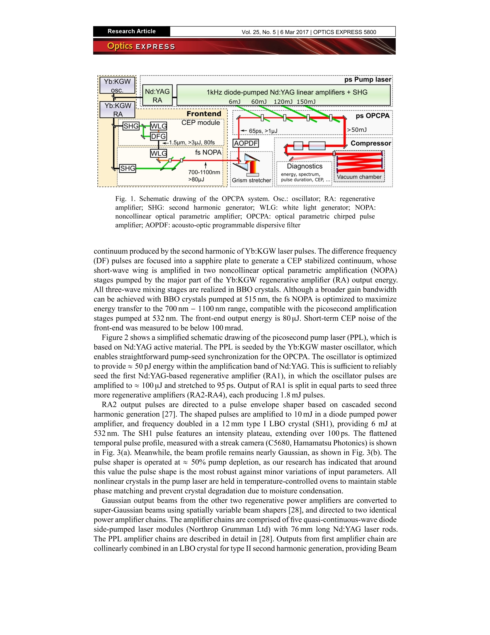
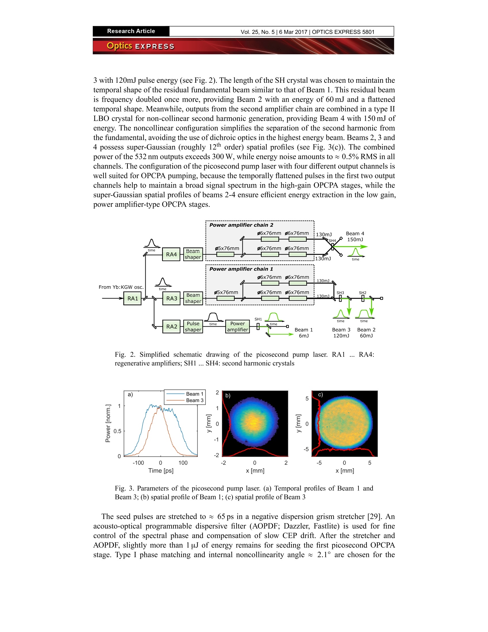
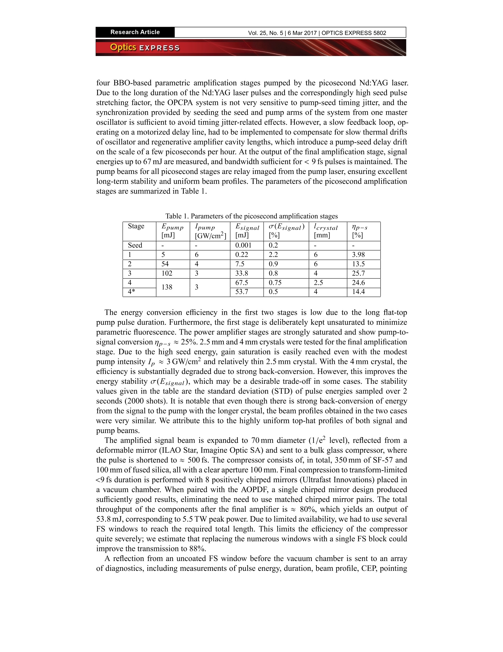
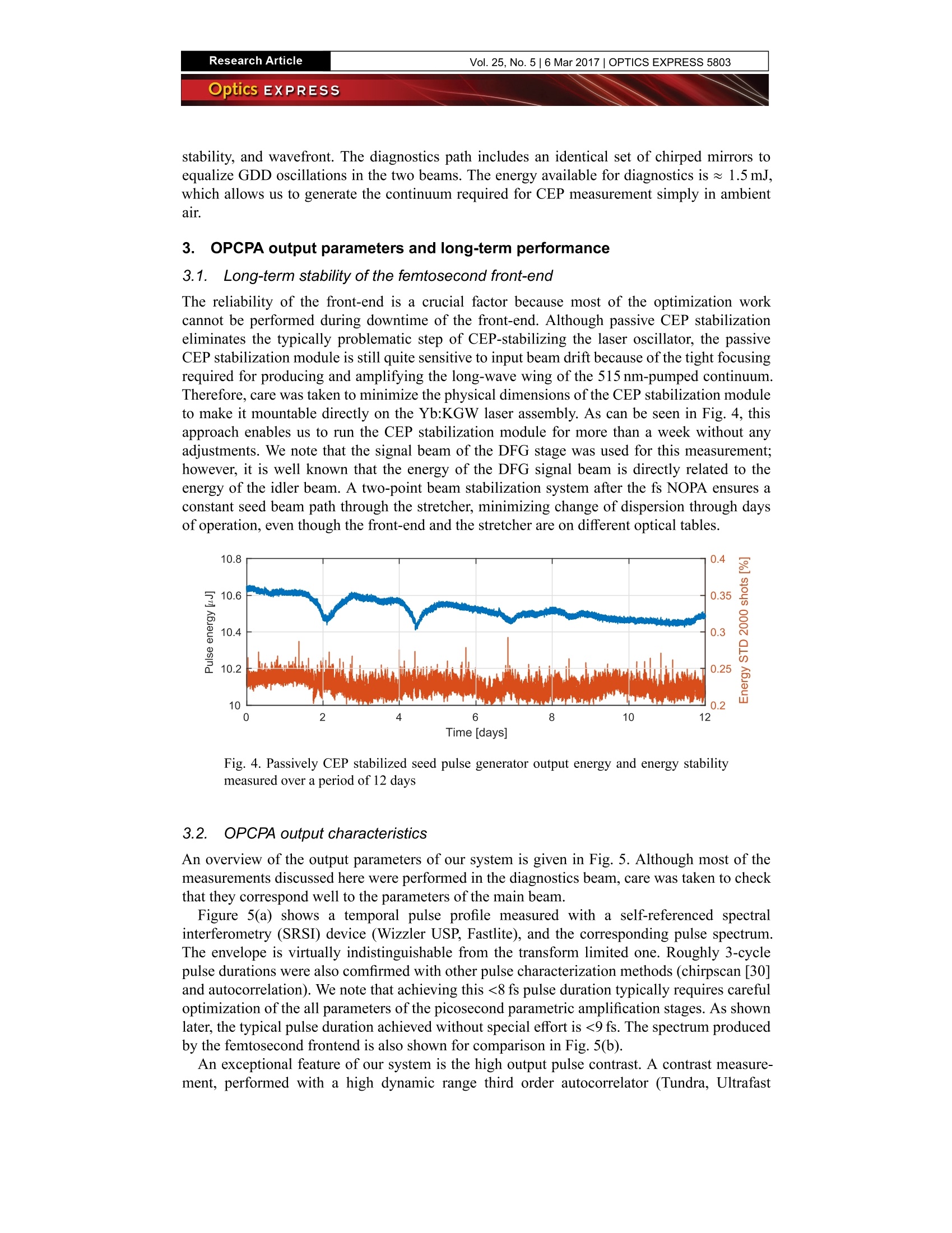
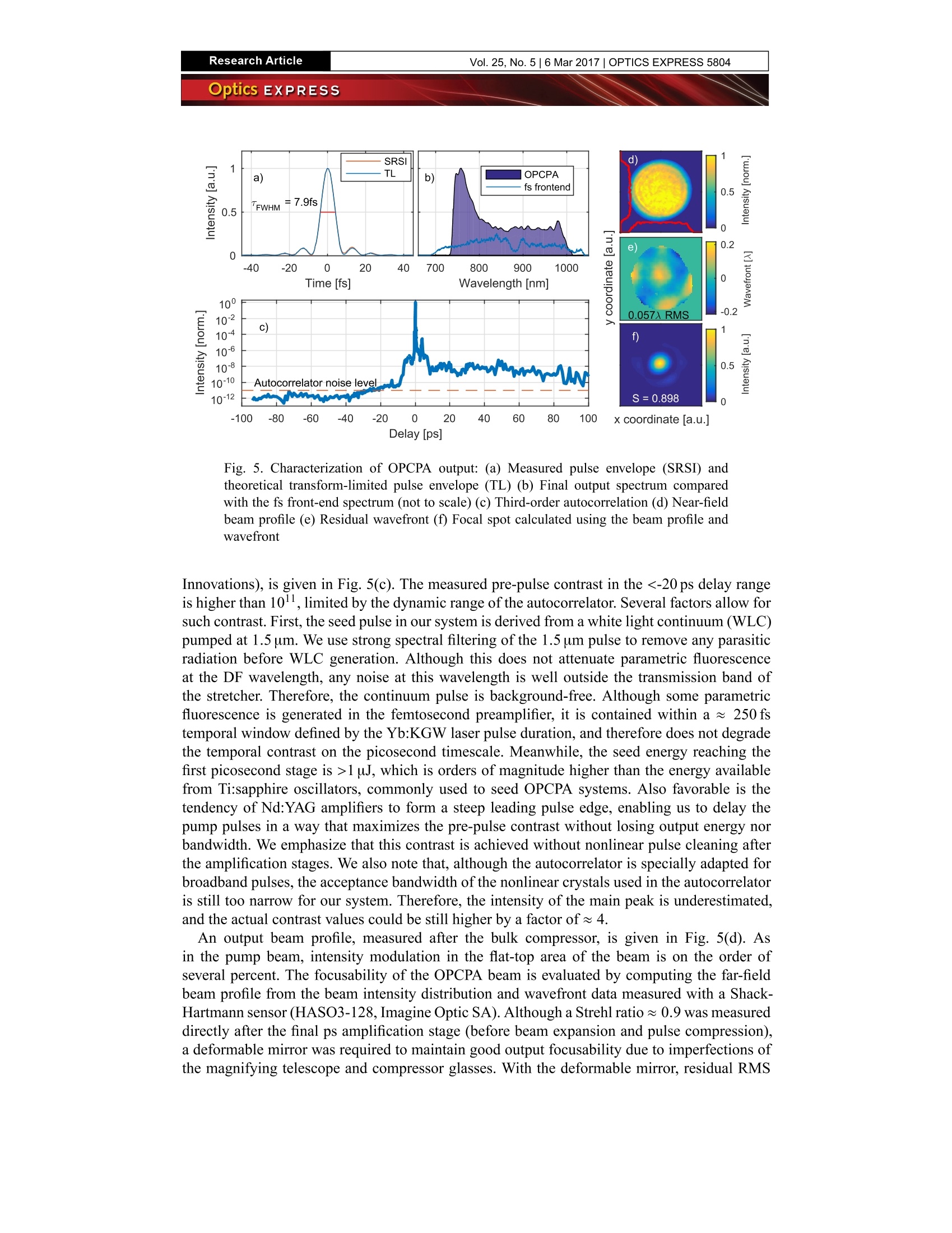
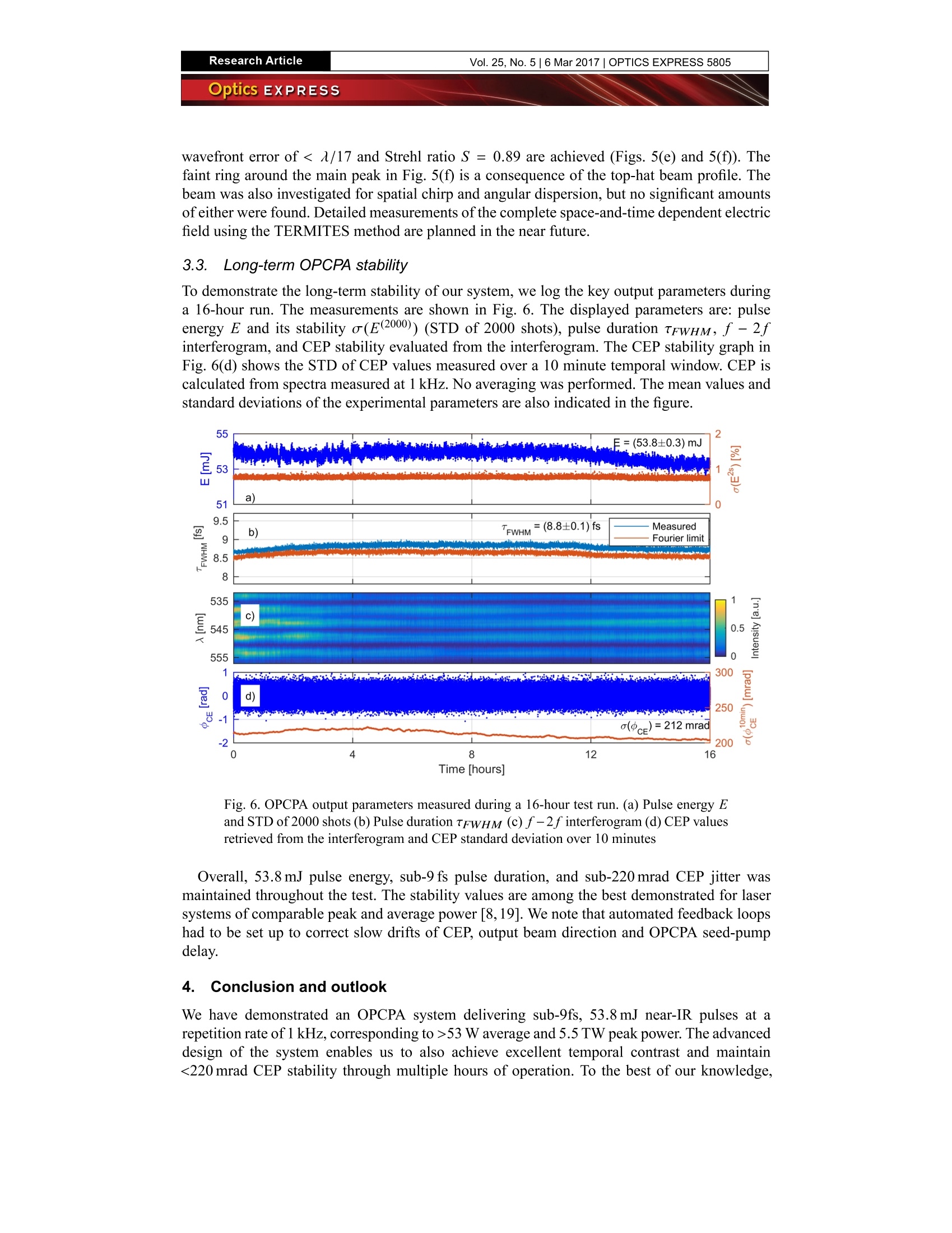
Research ArticleVol. 25,No.5|6 Mar 2017|OPTICS EXPRESS 5797Optics EXPRESS #284225Journal C 2017https://doi.org/10.1364/OE.25.005797Received 11 Jan 2017; revised 23 Feb 2017;accepted 25 Feb 2017; published 3 Mar 2017 53 W average power CEP-stabilized OPCPAsystem delivering 5.5 TW few cycle pulses at1 kHz repetition rate RIMANTAS BUDRIUNAS,1,2 TOMAS STANISLAUSKAS,1,2 JONAsADAMONIS,3 AIDAS ALEKNAVICIUS,3 GEDIMINAS VEITAS,2 DARIUSGADONAS, STANISLOVAS BALICKAS,’ ANDREJUS MICHAILOVAS,3,4AND ARUNAS VARANAVICIus1 Vilnius University Laser Research Center, Sauletekio Ave. 10, LT-10222 Vilnius, Lithuania Light Conversion Ltd., 2b Keramiky str, LT-10223 Vilnius, Lithuania Ekspla UAB, 237 Savanoriu Ave., LT-02300, Vilnius, Lithuania “Institute of Physics, Center for Physical Sciences and Technology, 231 Savanoriy Ave., LT-02300,Vilnius, Lithuania rimantas.budriunas@lightcon.com Abstract::We present a high peak and average power optical parametric chirped pulseamplification system driven by diode-pumped Yb:KGW and Nd:YAG lasers running at 1 kHzrepetition rate. The advanced architecture of the system allows us to achieve >53 W averagepower combined with 5.5 TW peak power, along with sub-220 mrad CEP stability and sub-9 fspulse duration at a center wavelength around 880 nm. Broadband, background-free, passivelyCEP stabilized seed pulses are produced in a series of cascaded optical parametric amplifierspumped by the Yb:KGW laser, while a diode-pumped Nd: YAG laser system provides multi-mJpump pulses for power amplification stages. Excellent stability of output parameters over 16hours of continuous operation is demonstrated. C2017 Optical Society of America OCIS codes: (190.4970) Parametric oscillators and amplifiers; (230.4320) Nonlinear optical devices; (140.3280) Laseramplifiers; (140.3480) Lasers, diode-pumped; (320.7090) Ultrafast lasers. References and links 1. A. Dubietis, G. Jonusauskas, and A. Piskarskas,“Powerful femtosecond pulse generation by chirped and stretchedpulse parametric amplification in BBO crystal,”Opt. Commun. 88(4-6), 437-440 (1992) 2.H. Fattahi, H. G. Barros, M. Gorjan, T. Nubbemeyer, B. Alsaif, C. Y. Teisset, M. Schultze, S. Prinz, M. Haefner,M. Ueffing, A. Alismail, L. Vamos, A. Schwarz, O. Pronin, J. Brons, X. T. Geng, G. Arisholm, M. Ciappina, V.S. Yakovlev, D.-E. Kim, A. M. Azzeer, N. Karpowicz, D. Sutter, Z. Major, T. Metzger, and F. Krausz,“Third-generation femtosecond technology,”Optica 1(1), 45-63 (2014) 3.B. Schenkel, J. Biegert, U. Keller, C. Vozzi, M. Nisoli, G. Sansone, S. Stagira, S. De Silvestri, and O. Svelto,“Generation of 3.8-fs pulses from adaptive compression of a cascaded hollow fiber supercontinuum,” Opt. Lett.28(20),1987-1989 (2003) 4.. FF. Silva, M. Miranda, B. Alonso, J. Rauschenberger, V. Pervak, and H. Crespo,“Simultaneous compression,characterization and phase stabilization of GW-level 1.4 cycle VIS-NIR femtosecond pulses using a singledispersion-scan setup,”Opt. Express 22(9),10181-10191 (2014) 5.S. Hadrich, M. Kienel, M. Muller, A. Klenke, J. Rothhardt,R. Klas, T. Gottschall, T. Eidam, A. Drozdy, P. Jojart, Z.Varallyay, E. Cormier, K. Osvay, A. Tiinnermann, and J. Limpert,“Energetic sub-2-cycle laser with 216 W averagepower," Opt. Lett. 41(18), 4332-4335 (2016) 6.F. Bohle, M. Kretschmar, A. Jullien, M. Kovacs, M. Miranda, R. Romero, H. Crespo, U. Morgner, P. Simon, R.Lopez-Martens, and T. Nagy,“Compression of CEP-stable multi-mJ laser pulses down to 4 fs in long hollow fibers,”Laser Phys. Lett. 11(9),095401 (2014) 7.SS. Bohman, A. Suda, T. Kanai, S. Yamaguchi, and K. Midorikawa “Generation of 5.0 fs, 5.0 mJ pulses at 1 kHzusing hollow-fiber pulse compression,”Opt. Lett. 35(11),1887-1889 (2010) 8.B. Langdon,J. Garlick, X. Ren, D. J. Wilson, A. M. Summers, S. Zigo, M. F. Kling, S. Lei, C.G. Elles, E. Wells,E. D. Poliakoff, K. D. Carnes, V.Kumarappan, I. Ben-Itzhak, and C. A. Trallero-Herrero,“Carrier-envelope-phasestabilized terawatt class laser at 1 kHz with a wavelength tunable option,”Opt. Express 23(4), 4563-4572(2015) 9.T. Stanislauskas, R. Budriunas, R. Antipenkov, A. Zaukevicius, J. Adamonis, A. Michailovas, L. Giniunas,R.Danielius, A. Piskarskas, and A. Varanavicius,“Table top TW-class OPCPA system driven by tandem femtosecond ( Yb:KGW an d pi c osecond Nd:YAG lasers,”Op t . Express 22(2), 1865- 1 870 (2014) ) 10. S. Witte, R. Th. Zinkstok, A. L. Wolf, W. Hogervorst, W. Ubachs, and K. S. E. Eikema, “A source of 2 terawatt,2.7 cycle laser pulses based on noncollinear optical parametric chirped pulse amplification,”Opt. Express 14(18),8168-8177 (2006) 11. D. Herrmann, L. Veisz, R. Tautz, F. Tavella, K. Schmid, V. Pervak, and F. Krausz, “Generation of sub-three-cycle,16 TW light pulses by using noncollinear optical parametric chirped-pulse amplification,”Opt. Lett. 34(16), 2459-2461(2009) 12. J. Rothhardt, S. Demmler, S. Hadrich, J. Limpert, and A. Tunnermann,“Octave-spanning OPCPA system deliveringCEP-stable few-cycle pulses and 22 W of average power at 1 MHz repetition rate,”Opt. Express 20(10), 10870-10878(2012) ( 13. L. E. Zapata, H. Lin, A.-L. Calendron, H. Cankaya, M. He m mer, F. R e ichert, W. R. H u an g , E. Gr a nados,K.-H.Hong, and F . X. Kartner,“ C ryogenic Yb:YAG composite-thin-disk for high energy and average power amplifiers,”Opt.Lett. 40(11), 2610 - 2613(2015) ) ( 14. M. M uller, M . K ienel, A . K lenke, T. G ottschall, E. Shestaev, M. Plotner, J . Limpert, and A. Tinnermann,“1 kW 1 m J eight-channel ultrafast fiber laser,” O pt. Lett. 41(15), 3439-3442 (2016) ) ( 15. K. M ichailovas, A . Baltuska, A. Pugzlys, V. S mi l gevicius, A. M i chailovas, A. Zaukev i cius, R. Dani l evicius, S. Frankinas,and N. Rusteika,“Combined Yb/Nd driver for op t ical parametric chirped pulse amplifiers,”Opt. Expres s 24(19),22261 - 22271(2016) ) ( 16.H. Fattahi, A. Alismail, H. Wang, J . Brons, O. Pronin, T. Buberl, L. Vamos, G. Arisholm, A. M. A zzeer, and F . K rausz,“High-power, 1-ps, all-Yb:YAG thin-disk regenerative amplifier,” O pt. Lett. 41(6),1126-1129 (2016) ) ( 17. L. E. Zapata, F. Reichert, M. Hemmer, and F. X. Kartner,“250 W average power, 100 k H z repetition rate cryogenicYb:YAG a m plifier for OPCPA pumping,”Opt. Lett. 41(3), 492-495 (2016) ) ( 18. M. S chulz, R. Riedel, A. Willner, T . Mans, C. Schnitzler, P. Russbueldt, J. D o lkemeyer, E. Seise, T. Go t tschall, S. Hadrich, S. Duesterer, H. Schlarb,J. Feldhaus, J. Limpert, B. Faatz , A. Tinnermann, J. Rossbach, M. D rescher, a ndF. T avella, “ Yb:YAG Innoslab amplifier: ef f icient h i gh r e petition r ate subpicosecond p u mping system for opticalparametric chirped pulse amplification, ” Opt. Lett . 36(13),2456-2458 (2011) ) ( 19. F. Batysta, R. Antipenkov, J. Novak, J . T. Green, J. A. Naylon, J . Horacek, M . Horácek, Z. Hubka, R. Boge, T. Mazanec, B. Himmel, P. Bakule, and B. Rus,“Broadband OPCPA system with 11 mJ o utput at 1 k H z, c ompressible to 12 fs,” Opt. Express 24(16), 1 7843-17848 (2016) ) ( 20.C. Homann and E. R iedle, “Direct mea s urement of the effective inpu t nois e powe r of an op t ic a l parametricamplifier,” L as. Phot. Rev 7(4), 580-588 (2013) ) 21. C. Manzoni, J. Moses, F. X. Kartner, and G. Cerullo,“Excess quantum noise in optical parametric chirped-pulseamplification,”Opt. Express 19(9), 8357-8366 (2011) ( 22. J. M. M ikhailova, A. Bu c k, A. Bor o t, K. S chmid, C. Sears, G. D. Ts a kiris, F. Kraus z , and L. Vei s z, “ Ultra- h igh- contrast few-cycle pulses for multipetawatt-class laser technology, ” Opt. Lett. 36(16), 3145-3147 (2011) ) ( 2 3. S . A dachi, N. Ishii, Y . Kobayashi, Y. Nomura, J. Itatani, T. Kanai, and S. Wa t anabe,“Carrier-envelope phase controlof few-cycle parametric chirped-pulse amplifier,”Jpn. J. A p pl. Phys. 49(3), 032703 (2010) ) ( 24. Y. Deng, A. Schwarz, H. Fattahi,M. Ueffing, X. Gu, M. O ssiander, T. Metzger, V. Perv a k, H. Ishizuki, T. Takunori, T.Kobayashi, G. M a rcus, F. Kr ausz, R. Kienberger, and N. Karpowicz,“Carrier-env e lope-phase-stable, 1.2 mJ, 1.5 cycle laser pulses at 2 . 1 um,” Opt. Lett. 37(23) , 4973-4975 (2012) ) ( 25. R. Budriunas, T. Stanislauskas, and A. Varanavicius, “ Passively C EP-stabilized f rontend f or few c ycle terawattOPCPA system,”J. Opt. 17(9), 094008-1- 0 94008-8(2015) ) ( 26. A. B altuska, T. Fuji, and T. Kobayashi,“Controlling t h e carrier-envelope phase ofultrashort l i ght pulses with opticalparametric amplifiers,” P hys. Rev. Lett.88(13), 1333901- 1 333905 (2002) ) 27. J. Adamonis, R. Antipenkov, J.Kolenda, A. Michailovas, A. P. Piskarskas, A. Varanavicius, and A. Zaukevicius,“Formation of flat top picosecond pump pulses for OPCPA systems by cascade second harmonic generation,”Lith.J. Phys. 52(3), 193-202 (2012) 28. J. Adamonis, A. Aleknavicius, K. Michailovas, S. Balickas, V. Petrauskiene, T. Gertus, and A. Michailovas,“Implementation ofa SVWP-based laser beam shaping technique for generation of 100-mJ-level picosecond pulses,”Appl. Opt. 55(28), 8007-8015 (2016) 29. T. H. Dou, R. Tautz, X. Gu, G. Marcus, T. Feurer, F. Krausz, and L. Veisz,“Dispersion control with reflection grismsof an ultra-broadband spectrum approaching a full octave,” Opt. Express 18(26),27900-27909 (2010) 30. V. Loriot, G. Gitzinger, and N. Forget,“Self-referenced characterization of femtosecond laser pulses by chirp scan,”Opt. Express 21(21), 24879-24893 (2013) 1.. Introduction Optical parametric chirped pulse amplification (OPCPA), first demonstrated in 1992 [1], isbecoming the standard technique for producing few cycle, high intensity pulses for attosecondscience and high field experiments [2]. So far, the dominant technology for generation ofintense pulses with durations down to the near-single-cycle regime has been nonlinear pulse compression in gas-filled capillaries [3, 4]. Although scaling of this approach to 216 W ofaverage power has been demonstrated [5], the output energy from hollow fiber compressorsis limited to a few mJ [6, 7] due to limited aperture of the capillaries. On the other hand,multimilijoule, CEP stabilized pulses with TW-level peak powers can be produced by advancedTi:sapphire systems, but the pulse duration is on the order of 25 fs [8]. OPCPA schemes basedon BBO crystals pumped by the second harmonic of lasers operating at 1um have beendemonstrated to be capable ofreaching TW peak power in low repetition rate flashlamp pumpedsystems [9-11], and produce few cycle pulses with much lower pulse energies, but at averagepxzhen nmnedower up to 22 W, when pumped by fiber-based lasers [12]. The recent massive improvementsin the quality and availability of diode-pumped, high average power solid-state lasers [2,13-19],providing multimillijoule pulses for OPCPA pumping at≥1 kHz repetition rates allows boostingthe average powers of few cycle TW-scale OPCPA system to the range of tens of watts. Alongside peak and average power, pulse temporal contrast is an extremely importantparameter that must be controlled in strong field experiments. In terms of output pulse contrast,OPCPA is advantageous to traditional chirped pulse amplification systems because of theinstantaneous nature of the process, which limits amplification to the temporal window definedby the pump pulse. However, it has been noted in the literature that if the OPCPA seed pulseis contaminated by amplified spontaneous emission (ASE), the ASE background is amplifiedalong with the signal within the temporal window of the pump pulse [11]. Furthermore, thecontrast of OPCPA output is always degraded by amplified parametric fluorescence (APF).Although APF is inevitable in a parametric amplifier, its level can be reduced by careful designof high-gain amplification stages [20], optimizing seed and pump pulse durations [21], usinghigher energy seed pulses, and employing nonlinear pulse cleaning techniques [11,22]. Carrierenvelope phase (CEP) control is another essential prerequisite for a number of the few cyclelaser applications in strong-field research, in particular for experiments on generation of isolatedatosecond pulses. Nowadays, both active and passive CEP stabilization are well establishedtechniques providing CEP control in different types of laser systems. However, only a few CEPstable few cycle OPCPA systems producing CEP-stable pulses with energies exceeding 1 mJhave been reported [23,24]. In this paper we present an OPCPA system consisting of femtosecond and picosecondnoncollinear parametric amplifiers seeded by passively stabilized broadband pulses from acontinuum generator. The system delivers sub-3-cycle, 53.8 mJ pulses, centered at 880 nm.Using a diode-pumped Nd:YAG laser system as the pump source allows us to produce thesepulses at 1 kHz repetition rate, corresponding to >53 W average power. We show how severalimprovements to the well-known OPCPA scheme based on BBO crystals pumped at 532 nmallow us to combine the few-cycle pulse duration and multi-TW peak power with passive, sub-220 mrad CEP noise, high temporal contrast, and excellent long-term stability. To the best ofour knowledge, the system described here delivers the highest average power currently achievedamong CEP-stabilized, few-cycle,TW-class laser systems. 2.1. (OPCPA setup The layout of the OPCPA setup is presented in Fig. 1. The system consists of a front-endbased on a commercial industrial-grade femtosecond Yb:KGW laser (Pharos, Light ConversionLtd.), a specially designed diode-pumped Nd:YAG picosecond pump laser (Ekspla UAB), and4 picosecond OPCPA stages, preceded by a seed pulse stretcher (grism pair + acoustoopticprogrammable dispersive filter) and followed by a compressor (bulk glasses and positive GDDchirped mirrors). The design of the femtosecond front-end is based on our previous setup described in detailin [25]. Passively CEP stabilized pulses [26] at 1.5 um are produced by generating the differencefrequency between frequency doubled Yb:KGW laser pulses and the long-wave wing of a Fig. 1. Schematic drawing of the OPCPA system. Osc.: oscillator; RA: regenerativeamplifier; SHG: second harmonic generator; WLG: white light generator; NOPA:noncollinear optical parametric amplifier; OPCPA: optical parametric chirped pulseamplifier; AOPDF: acousto-optic programmable dispersive filter continuum produced by the second harmonic ofYb:KGW laser pulses. The difference frequency(DF) pulses are focused into a sapphire plate to generate a CEP stabilized continuum, whoseshort-wave wing is amplified in two noncollinear optical parametric amplification (NOPA)stages pumped by the major part of the Yb:KGW regenerative amplifier (RA) output energy.All three-wave mixing stages are realized in BBO crystals. Although a broader gain bandwidthcan be achieved with BBO crystals pumped at 515 nm, the fs NOPA is optimized to maximizeenergy transfer to the 700 nm - 1100 nm range, compatible with the picosecond amplificationstages pumped at 532 nm. The front-end output energy is 80 uJ. Short-term CEP noise of thefront-end was measured to be below 100 mrad. Figure 2 shows a simplified schematic drawing of the picosecond pump laser (PPL), which isbased on Nd:YAG active material. The PPL is seeded by the Yb:KGW master oscillator, whichenables straightforward pump-seed synchronization for the OPCPA. The oscillator is optimizedto provide≈50 pJ energy within the amplification band of Nd:YAG. This is sufficient to reliablyseed the first Nd:YAG-based regenerative amplifier (RA1), in which the oscillator pulses areamplified to ≈ 100 uJ and stretched to 95 ps. Output ofRA1 is split in equal parts to seed threemore regenerative amplifiers (RA2-RA4), each producing 1.8 mJ pulses. RA2 output pulses are directed to a pulse envelope shaper based on cascaded secondharmonic generation [27]. The shaped pulses are amplified to 10 mJ in a diode pumped poweramplifier, and frequency doubled in a 12 mm type I LBO crystal (SH1), providing 6 mJ at532 nm. The SH1 pulse features an intensity plateau, extending over 100 ps. The flattenedtemporal pulse profile, measured with a streak camera (C5680, Hamamatsu Photonics) is shownin Fig. 3(a). Meanwhile, the beam profile remains nearly Gaussian, as shown in Fig. 3(b). Thepulse shaper is operated at ~ 50% pump depletion, as our research has indicated that aroundthis value the pulse shape is the most robust against minor variations of input parameters. Allnonlinear crystals in the pump laser are held in temperature-controlled ovens to maintain stablephase matching and prevent crystal degradation due to moisture condensation. Gaussian output beams from the other two regenerative power amplifiers are converted tosuper-Gaussian beams using spatially variable beam shapers [28], and directed to two identicalpower amplifier chains. The amplifier chains are comprised of five quasi-continuous-wave diodeside-pumped laser modules (Northrop Grumman Ltd) with 76 mm long Nd:YAG laser rods.The PPL amplifier chains are described in detail in [28]. Outputs from first amplifier chain arecollinearly combined in an LBO crystal for type II second harmonic generation, providing Beam 3 with 120mJ pulse energy (see Fig.2). The length of the SH crystal was chosen to maintain thetemporal shape of the residual fundamental beam similar to that of Beam 1. This residual beamis frequency doubled once more, providing Beam 2 with an energy of 60 mJ and a flattenedtemporal shape. Meanwhile, outputs from the second amplifier chain are combined in a type IILBO crystal for non-collinear second harmonic generation, providing Beam 4 with 150 mJ ofenergy. The noncollinear configuration simplifies the separation of the second harmonic fromthe fundamental, avoiding the use of dichroic optics in the highest energy beam. Beams 2,3 and4 possess super-Gaussian (roughly 12h order) spatial profiles (see Fig. 3(c)). The combinedpower of the 532 nm outputs exceeds 300 W, while energy noise amounts to ~ 0.5% RMS in allchannels. The configuration of the picosecond pump laser with four different output channels iswell suited for OPCPA pumping, because the temporally flattened pulses in the first two outputchannels help to maintain a broad signal spectrum in the high-gain OPCPA stages, while thesuper-Gaussian spatial profiles of beams 2-4 ensure efficient energy extraction in the low gain,power amplifier-type OPCPA stages. Fig. 2. Simplified schematic drawing of the picosecond pump laser. RA1... RA4:regenerative amplifiers; SH1 ... SH4: second harmonic crystals Fig. 3. Parameters of the picosecond pump laser. (a) Temporal profiles of Beam 1 andBeam 3;(b) spatial profile of Beam 1; (c) spatial profile of Beam 3 The seed pulses are stretched to ~ 65 ps in a negative dispersion grism stretcher [29]. Anacousto-optical programmable dispersive filter (AOPDF; Dazzler, Fastlite) is used for finecontrol of the spectral phase and compensation of slow CEP drift. After the stretcher andAOPDF, slightly more than 1 uJ of energy remains for seeding the first picosecond OPCPAstage. Type I phase matching and internal noncollinearity angle ~ 2.1° are chosen for the four BBO-based parametric amplification stages pumped by the picosecond Nd:YAG laser.Due to the long duration of the Nd:YAG laser pulses and the correspondingly high seed pulsestretching factor, the OPCPA system is not very sensitive to pump-seed timing jitter, and thesynchronization provided by seeding the seed and pump arms of the system from one masteroscillator is sufficient to avoid timing jitter-related effects. However, a slow feedback loop, op-erating on a motorized delay line, had to be implemented to compensate for slow thermal driftsof oscillator and regenerative amplifier cavity lengths, which introduce a pump-seed delay drifton the scale of a few picoseconds per hour. At the output of the final amplification stage, signalenergies up to 67 mJ are measured, and bandwidth sufficient for < 9 fs pulses is maintained. Thepump beams for all picosecond stages are relay imaged from the pump laser, ensuring excellentlong-term stability and uniform beam profiles. The parameters of the picosecond amplificationstages are summarized in Table 1. Table 1. Parameters of the picosecond amplification stages Stage EpumpmJ| pump [GW/cm21 EsignalmJ| o(Esignal) crystalmm] 7p-s[%] Seed - - 0.001 0.2 - 1 5 6 0.22 2.2 6 3.98 2 54 4 7.5 0.9 6 13.5 3 102 3 33.8 0.8 4 25.7 4 138 3 67.5 0.75 2.5 24.6 4* 53.7 0.5 4 14.4 The energy conversion efficiency in the first two stages is low due to the long flat-toppump pulse duration. Furthermore, the first stage is deliberately kept unsaturated to minimizeparametric fluorescence. The power amplifier stages are strongly saturated and show pump-to-signal conversion np-s ≈25%.2.5 mm and 4 mm crystals were tested for the final amplificationstage. Due to the high seed energy, gain saturation is easily reached even with the modestpump intensity Ip~ 3 GW/cm² and relatively thin 2.5 mm crystal. With the 4 mm crystal, theefficiency is substantially degraded due to strong back-conversion. However, this improves theenergy stability o(Esignal), which may be a desirable trade-off in some cases. The stabilityvalues given in the table are the standard deviation (STD) of pulse energies sampled over 2seconds (2000 shots). It is notable that even though there is strong back-conversion of energyfrom the signal to the pump with the longer crystal, the beam profiles obtained in the two caseswere very similar. We attribute this to the highly uniform top-hat profiles of both signal andpump beams. The amplified signal beam is expanded to 70 mm diameter (1/elevel), reflected from adeformable mirror (ILAO Star, Imagine Optic SA) and sent to a bulk glass compressor, wherethe pulse is shortened to ~ 500 fs. The compressor consists of, in total, 350 mm of SF-57 and100 mm of fused silica, all with a clear aperture 100 mm. Final compression to transform-limited<9fs duration is performed with 8 positively chirped mirrors (Ultrafast Innovations) placed ina vacuum chamber. When paired with the AOPDF, a single chirped mirror design producedsufficiently good results, eliminating the need to use matched chirped mirror pairs. The totalthroughput of the components after the final amplifier is ≈ 80%, which yields an output of53.8 mJ, corresponding to 5.5 TW peak power. Due to limited availability, we had to use severalFS windows to reach the required total length. This limits the efficiency of the compressorquite severely; we estimate that replacing the numerous windows with a single FS block couldimprove the transmission to 88%. A reflection from an uncoated FS window before the vacuum chamber is sent to an arrayof diagnostics, including measurements of pulse energy, duration, beam profile, CEP, pointing stability, and wavefront. The diagnostics path includes an identical set of chirped mirrors toequalize GDD oscillations in the two beams. The energy available for diagnostics is ≈ 1.5 mJ,which allows us to generate the continuum required for CEP measurement simply in ambientair. 3. OPCPA output parameters and long-term performance 3.1. Long-term stability of the femtosecond front-end The reliability of the front-end is a crucial factor because most of the optimization workcannot be performed during downtime of the front-end. Although passive CEP stabilizationeliminates the typically problematic step of CEP-stabilizing the laser oscillator, the passiveCEP stabilization module is still quite sensitive to input beam drift because of the tight focusingrequired for producing and amplifying the long-wave wing of the 515 nm-pumped continuum.Therefore, care was taken to minimize the physical dimensions of the CEP stabilization moduleto make it mountable directly on the Yb:KGW laser assembly. As can be seen in Fig. 4, thisapproach enables us to run the CEP stabilization module for more than a week without anyadjustments. We note that the signal beam of the DFG stage was used for this measurement;however, it is well known that the energy of the DFG signal beam is directly related to theenergy of the idler beam. A two-point beam stabilization system after the fs NOPA ensures aconstant seed beam path through the stretcher, minimizing change of dispersion through daysof operation, even though the front-end and the stretcher are on different optical tables. Fig. 4. Passively CEP stabilized seed pulse generator output energy and energy stabilitymeasured over a period of 12 days 3.2. OPCPA output characteristics An overview of the output parameters of our system is given in Fig. 5. Although most of themeasurements discussed here were performed in the diagnostics beam, care was taken to checkthat they correspond well to the parameters of the main beam. Figure 5(a) shows a temporal pulse profile measured with a self-referenced spectralinterferometry (SRSI) device (Wizzler USP, Fastlite), and the corresponding pulse spectrum.The envelope is virtually indistinguishable from the transform limited one. Roughly 3-cyclepulse durations were also comfirmed with other pulse characterization methods (chirpscan [30]and autocorrelation). We note that achieving this <8 fs pulse duration typically requires carefuloptimization of the all parameters of the picosecond parametric amplification stages. As shownlater, the typical pulse duration achieved without special effort is <9 fs. The spectrum producedby the femtosecond frontend is also shown for comparison in Fig.5(b). An exceptional feature of our system is the high output pulse contrast. A contrast measure-ment, performed with a high dynamic range third order autocorrelator (Tundra, Ultrafast Delay [ps] Fig. 5. Characterization of OPCPA output: (a) Measured pulse envelope (SRSI) andtheoretical transform-limited pulse envelope (TL) (b) Final output spectrum comparedwith the fs front-end spectrum (not to scale) (c) Third-order autocorrelation (d) Near-fieldbeam profile (e) Residual wavefront (f) Focal spot calculated using the beam profile andwavefront Innovations), is given in Fig. 5(c). The measured pre-pulse contrast in the<-20 ps delay rangeis higher than 10ll, limited by the dynamic range of the autocorrelator. Several factors allow forsuch contrast. First, the seed pulse in our system is derived from a white light continuum (WLC)pumped at 1.5 um.We use strong spectral filtering of the 1.5 um pulse to remove any parasiticradiation before WLC generation. Although this does not attenuate parametric fluorescenceat the DF wavelength, any noise at this wavelength is well outside the transmission band ofthe stretcher. Therefore, the continuum pulse is background-free. Although some parametricfluorescence is generated in the femtosecond preamplifier, it is contained within a ~ 250 fstemporal window defined by the Yb:KGW laser pulse duration, and therefore does not degradethe temporal contrast on the picosecond timescale. Meanwhile, the seed energy reaching thefirst picosecond stage is >1 uJ, which is orders of magnitude higher than the energy availablefrom Ti:sapphire oscillators, commonly used to seed OPCPA systems. Also favorable is thetendency of Nd:YAG amplifiers to form a steep leading pulse edge, enabling us to delay thepump pulses in a way that maximizes the pre-pulse contrast without losing output energy norbandwidth. We emphasize that this contrast is achieved without nonlinear pulse cleaning afterthe amplification stages. We also note that, although the autocorrelator is specially adapted forbroadband pulses, the acceptance bandwidth of the nonlinear crystals used in the autocorrelatoris still too narrow for our system. Therefore, the intensity of the main peak is underestimated,and the actual contrast values could be still higher by a factor of~4. An output beam profile, measured after the bulk compressor, is given in Fig. 5(d). Asin the pump beam, intensity modulation in the flat-top area of the beam is on the order ofseveral percent. The focusability of the OPCPA beam is evaluated by computing the far-fieldbeam profile from the beam intensity distribution and wavefront data measured with a Shack-Hartmann sensor (HASO3-128, Imagine Optic SA). Although a Strehl ratio ~0.9 was measureddirectly after the final ps amplification stage (before beam expansion and pulse compression),a deformable mirror was required to maintain good output focusability due to imperfections ofthe magnifying telescope and compressor glasses. With the deformable mirror, residual RMS wavefront error of < /17 and Strehl ratio S = 0.89 are achieved (Figs. 5(e) and 5(f)). Thefaint ring around the main peak in Fig. 5(f) is a consequence of the top-hat beam profile. Thebeam was also investigated for spatial chirp and angular dispersion, but no significant amountsof either were found. Detailed measurements of the complete space-and-time dependent electricfield using the TERMITES method are planned in the near future. 3.3.Long-term OPCPA stability To demonstrate the long-term stability of our system, we log the key output parameters duringa 16-hour run. The measurements are shown in Fig. 6. The displayed parameters are: pulseenergy E and its stability o(E(2000)) (STD of 2000 shots), pulse duration TFWHM, f-2finterferogram, and CEP stability evaluated from the interferogram. The CEP stability graph inFig. 6(d) shows the STD of CEP values measured over a 10 minute temporal window. CEP iscalculated from spectra measured at 1 kHz. No averaging was performed. The mean values andstandard deviations of the experimental parameters are also indicated in the figure. Fig. 6. OPCPA output parameters measured during a 16-hour test run. (a) Pulse energy Eand STD of 2000 shots (b) Pulse duration TFWHM (c) f-2f interferogram (d) CEP valuesretrieved from the interferogram and CEP standard deviation over 10 minutes Overall, 53.8 mJ pulse energy, sub-9fs pulse duration, and sub-220 mrad CEP jitter wasmaintained throughout the test. The stability values are among the best demonstrated for lasersystems of comparable peak and average power [8,19]. We note that automated feedback loopshad to be set up to correct slow drifts of CEP, output beam direction and OPCPA seed-pumpdelay. 4. Conclusion and outlook We have demonstrated an OPCPA system delivering sub-9fs, 53.8 mJ near-IR pulses at arepetition rate of 1 kHz, corresponding to>53 W average and 5.5 TW peak power. The advanceddesign of the system enables us to also achieve excellent temporal contrast and maintain<220 mrad CEP stability through multiple hours of operation. To the best of our knowledge, our system produces the highest average power among CEP-stabilized, multi-TW, few-cycleOPCPA systems reported in the literature. In the near future, an upgrade is planned, which is expected to enable generation of 6 fspulses by adding LBO-based OPCPA stages to extend the spectrum to the long-wave side. Theupgraded laser system will be installed at the ELI-ALPS laser facility in Szeged, Hungary. Funding Lietuvos Mokslo Taryba (MIP-055/2014); Seventh Framework Programme (284464). We present a high peak and average power optical parametric chirped pulseamplification system driven by diode-pumped Yb:KGW and Nd:YAG lasers running at 1 kHzrepetition rate. The advanced architecture of the system allows us to achieve >53W averagepower combined with 5.5TW peak power, along with sub-220 mrad CEP stability and sub-9 fspulse duration at a center wavelength around 880 nm. Broadband, background-free, passively CEP stabilized seed pulses are produced in a series of cascaded optical parametric amplifiers pumped by the Yb:KGW laser, while a diode-pumped Nd:YAG laser system provides multi-mJ pump pulses for power amplification stages. Excellent stability of output parameters over 16 hours of continuous operation is demonstrated.
确定

还剩8页未读,是否继续阅读?

产品配置单
北京欧兰科技发展有限公司为您提供《可调谐激光器中平均功率、峰值功率检测方案(激光产品)》,该方案主要用于其他中平均功率、峰值功率检测,参考标准--,《可调谐激光器中平均功率、峰值功率检测方案(激光产品)》用到的仪器有Ekspla APL2200 高能量千赫兹皮秒放大器
推荐专场
相关方案
更多
该厂商其他方案
更多