


方案详情
文
This paper presents quantitative planar laserinduced
fluorescence (PLIF) imaging of nitric oxide (NO) in a
transient-arc direct-current plasmatron igniter using premixed
air/fuel mixtures. Quantitative measurements of NO are reported
as a function of gas flow rate (20–50 standard cubic feet per
hour), plasma power (100–900 mA, 150–750 W), and equivalence
ratio (0.7–1.3). Images were corrected for temperature effects by
using 2-D temperature field measurements obtained with infrared
thermometry and calibrated by a more accurate multiline fitting
technique. The signals were then quantified using an NO addition
method and spectroscopic laser-induced fluorescence modeling
of NO. NO PLIF images and single-point NO concentrations
are presented for both plasma-discharge-only and methane/air
plasma-enhanced combustion cases. NO formation occurs predominantly
through N2(v) + O → NO + N for the plasmadischarge-
only case without combustion. The NO concentration
for the plasma-enhanced combustion case (500–3500 ppm) was
an order of magnitude less than the plasma-discharge-only case
(8000–15 000 ppm) due to the reduction of plasma reactions by the
methane. Experiments show the linear decay of NO from equivalence
ratio 0.8–1.2 under the same flow condition and discharge
current.
Index Terms—Nitric oxide (NO), plasma torch, plasma-assisted
combustion.
方案详情

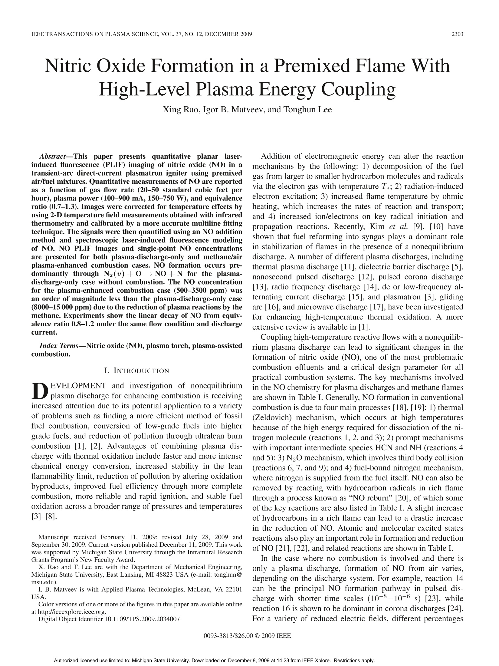
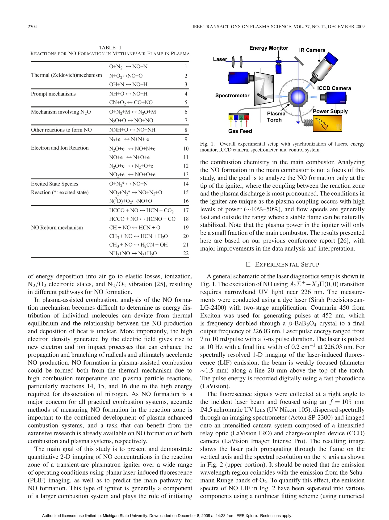
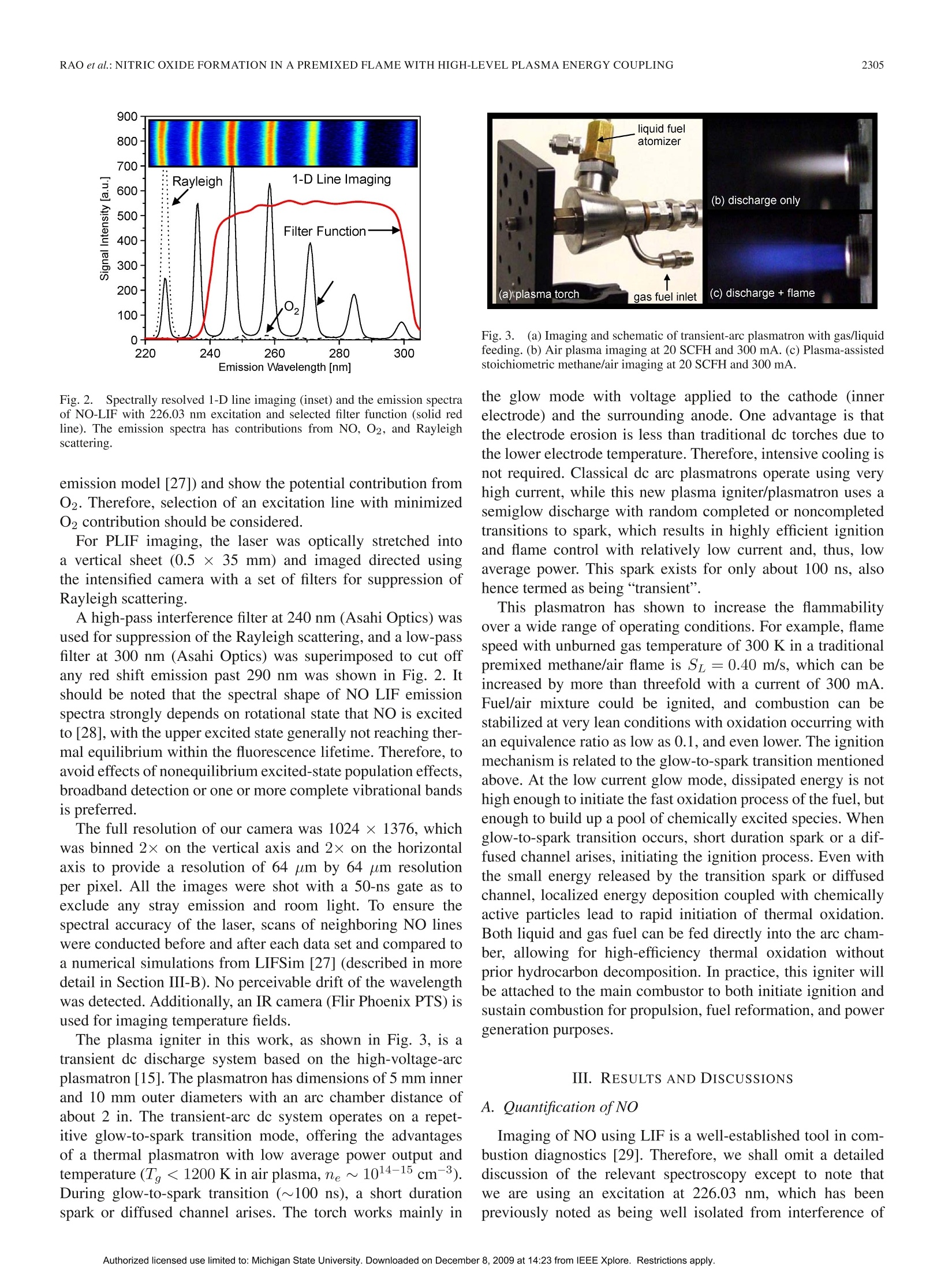
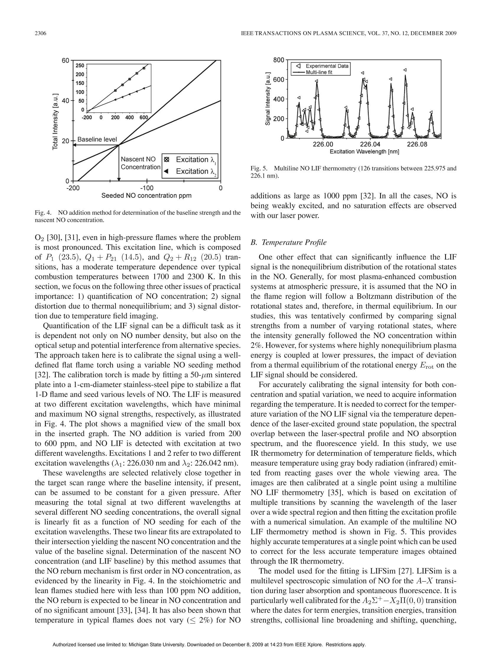
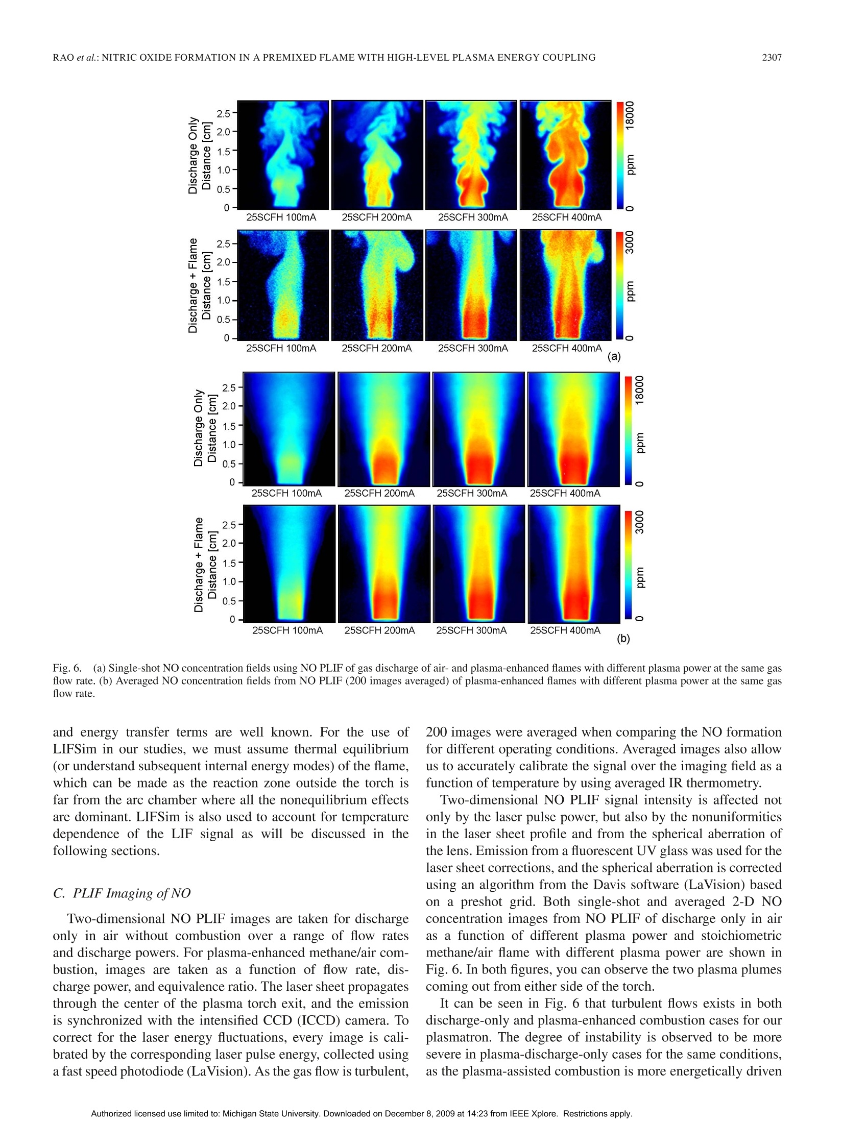
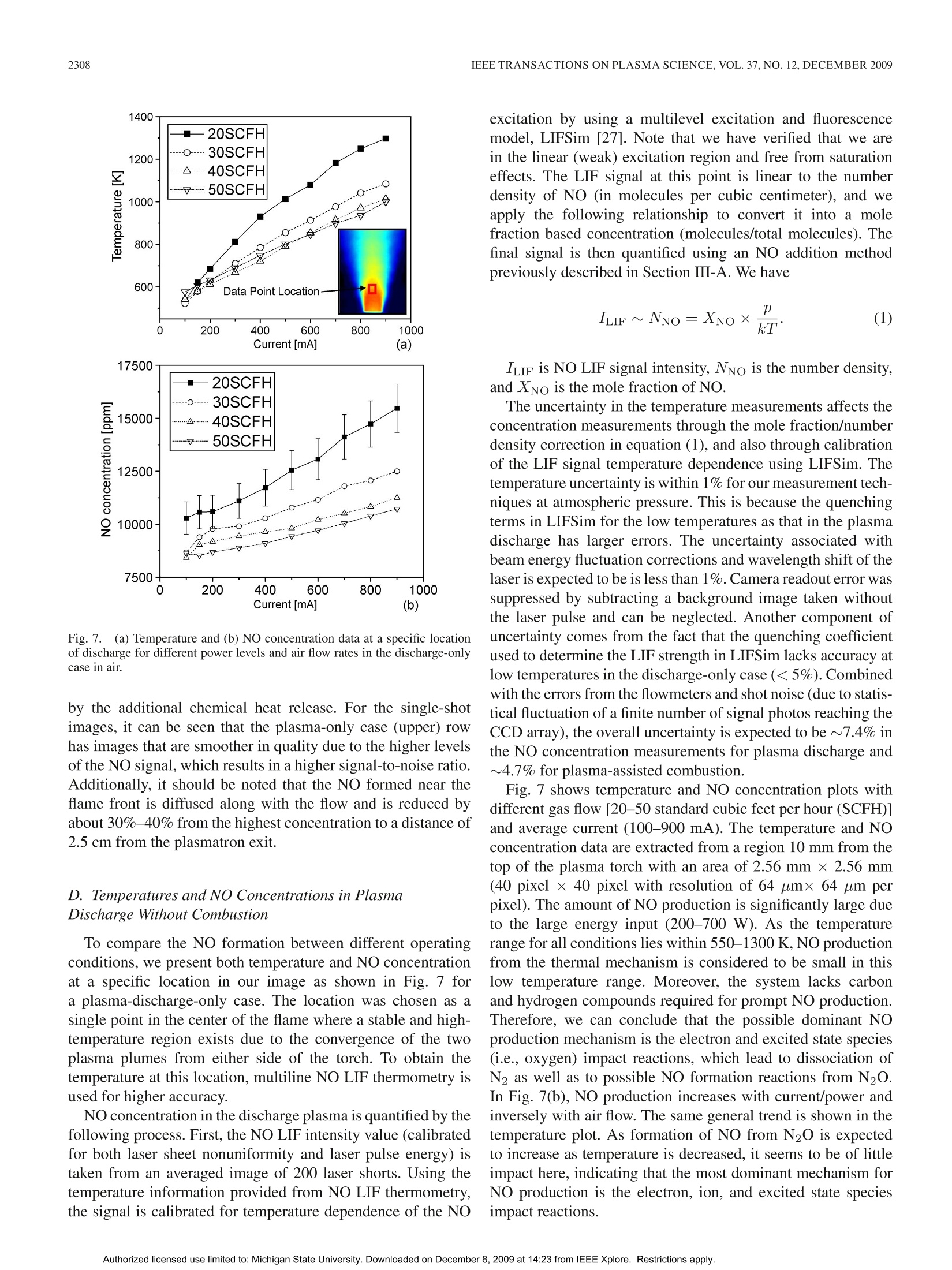
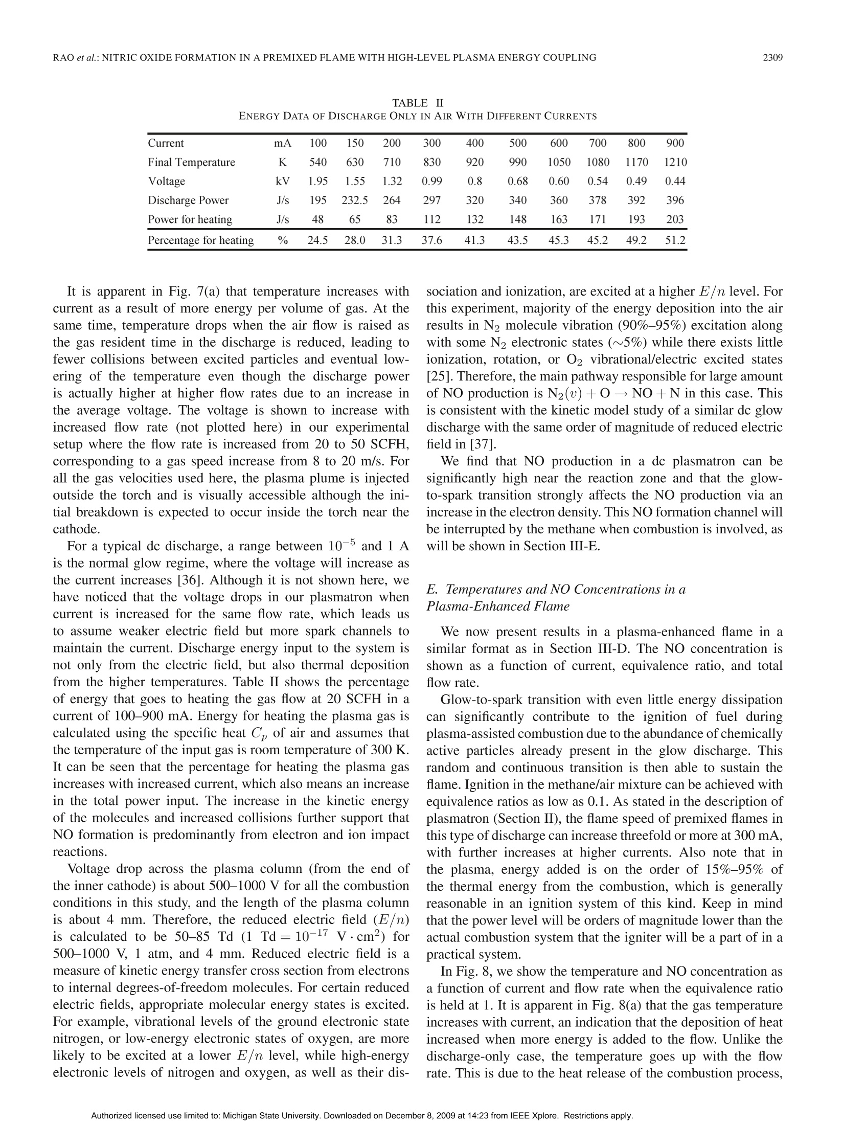
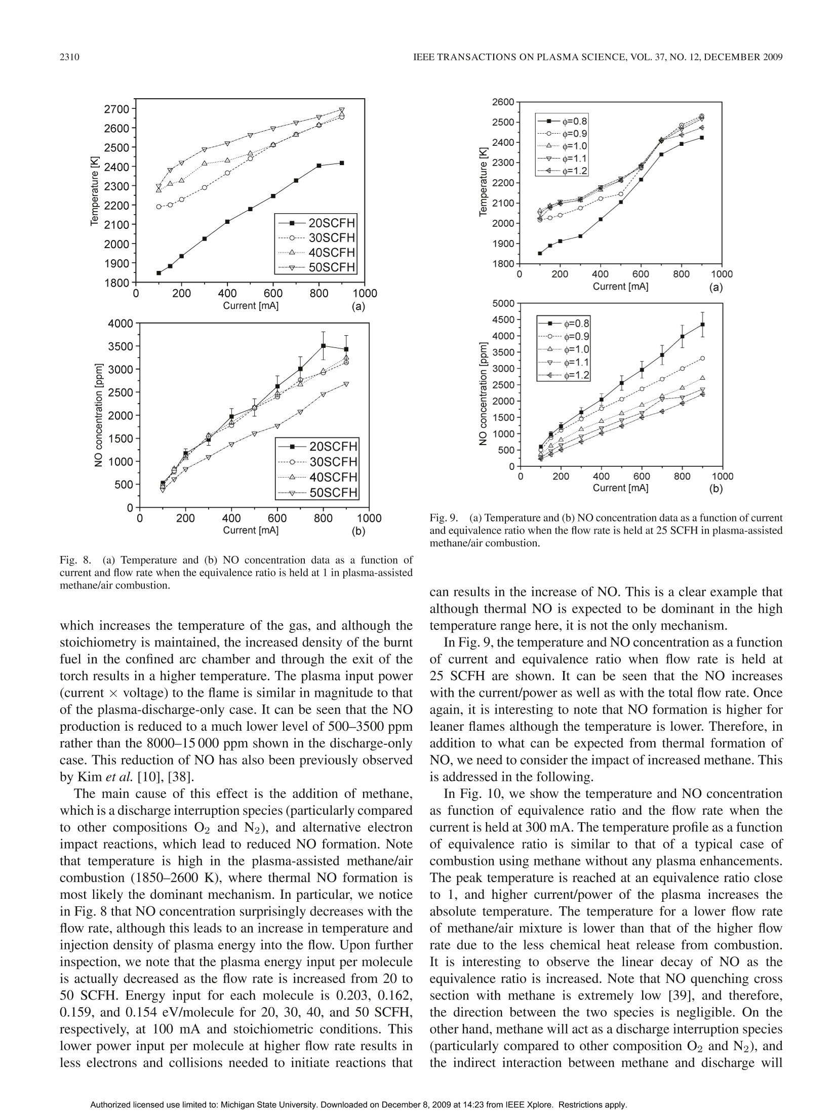
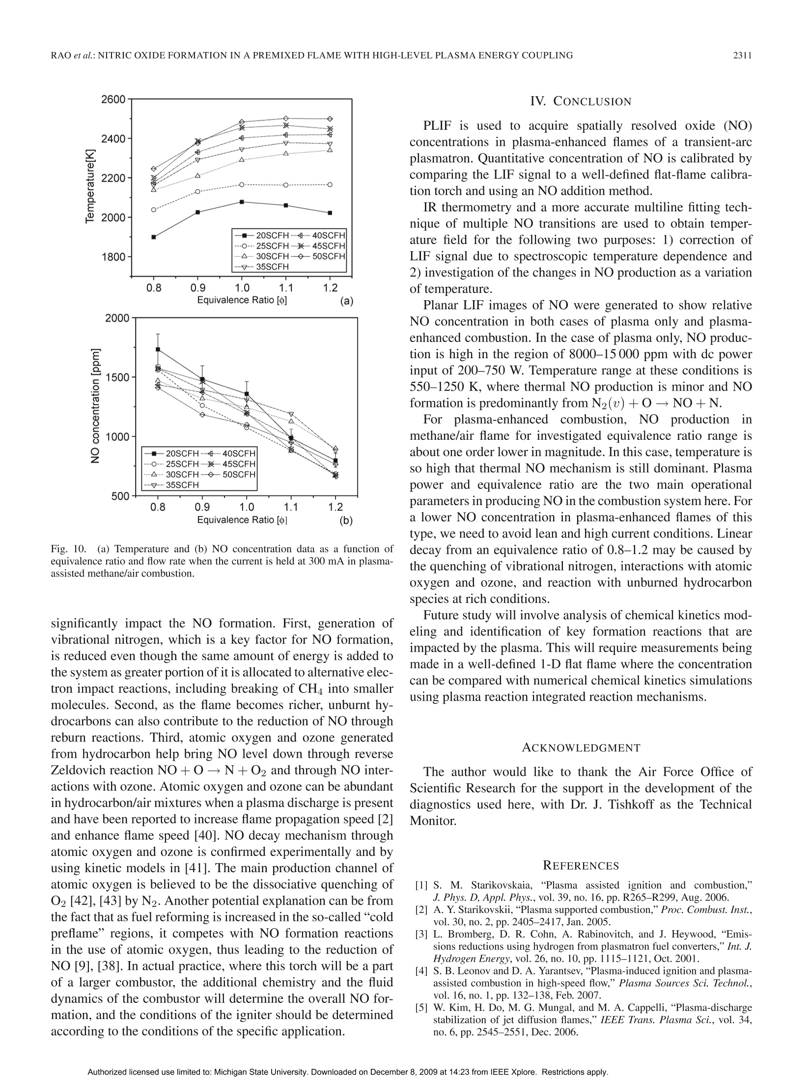
IEEE TRANSACTIONS ON PLASMA SCIENCE, VOL.37, NO.12,DECEMBER 20092303 IEEE TRANSACTIONS ON PLASMA SCIENCE, VOL. 37,NO. 12,DECEMBER 20092304 Nitric Oxide Formation in a Premixed Flame WithHigh-Level Plasma Energy Coupling Xing Rao, Igor B. Matveev, and Tonghun Lee Abstract-This paper presentss quantitative planar laser-induced fluorescence (PLIF) imaging of nitric oxide (NO) in atransient-arc direct-current plasmatron igniter using premixedair/fuel mixtures. Quantitative measurements of NO are reportedas a function of gas flow rate (20-50 standard cubic feet perhour), plasma power (100-900 mA, 150-750 W), and equivalenceratio (0.7-1.3). Images were corrected for temperature effects byusing 2-D temperature field measurements obtained with infraredthermometry and calibrated by a more accurate multiline fittingtechnique. The signals were then quantified using an NO additionmethod and spectroscopic laser-induced fluorescence modelingof NO. NO PLIF images and single-point NO concentrationsare presented for both plasma-discharge-only and methane/airplasma-enhanced combustion cases. NO formation occurs pre-dominantly through N2(u)+0→NO+N for the plasma-discharge-only case without combustion. The NO concentrationfor the plasma-enhanced combustion case (500-3500 ppm) wasan order of magnitude less than the plasma-discharge-only case(8000-15000 ppm) due to the reduction of plasma reactions by themethane. Experiments show the linear decay of NO from equiv-alence ratio 0.8-1.2 under the same flow condition and dischargecurrent. Index Terms-Nitric oxide (NO), plasma torch, plasma-assistedcombustion. I. INTRODUCTION EVELOPMENT and investigation of nonequilibriumDplasma discharge for enhancing combustion is receivingincreased attention due to its potential application to a varietyof problems such as finding a more efficient method of fossilfuel combustion, conversion of low-grade fuels into highergrade fuels, and reduction of pollution through ultralean burncombustion [1], [2]. Advantages of combining plasma dis-charge with thermal oxidation include faster and more intensechemical energy conversion, increased stability in the leanflammability limit, reduction of pollution by altering oxidationbyproducts, improved fuel efficiency through more completecombustion, more reliable and rapid ignition, and stable fueloxidation across a broader range of pressures and temperatures[3]-[8]. Manuscript received February 11, 2009; revised July 28, 2009 andSeptember 30, 2009. Current version published December 11, 2009. This workwas supported by Michigan State University through the Intramural ResearchGrants Program’s New Faculty Award. X. Rao and T. Lee are with the Department of Mechanical Engineering,Michigan State University, East Lansing, MI 48823 USA (e-mail: tonghun@msu.edu). I. B. Matveev is with Applied Plasma Technologies, McLean, VA 22101USA. Color versions of one or more of the figures in this paper are available onlineat http://ieeexplore.ieee.org. Digital Object Identifier 10.1109/TPS.2009.2034007 Addition of electromagnetic energy can alter the reactionmechanisms by the following:1) decomposition of the fuelgas from larger to smaller hydrocarbon molecules and radicalsvia the electron gas with temperature Te;2) radiation-inducedelectron excitation; 3) increased flame temperature by ohmicheating, which increases the rates of reaction and transport;and 4) increased ion/electrons on key radical initiation andpropagation reactions. Recently, Kim et al. [9], [10] haveshown that fuel reforming into syngas plays a dominant rolein stabilization of flames in the presence of a nonequilibriumdischarge. A number of different plasma discharges, includingthermal plasma discharge [11], dielectric barrier discharge [5],nanosecond pulsed discharge [12], pulsed corona discharge[13], radio frequency discharge [14], dc or low-frequency al-ternating current discharge [15], and plasmatron [3], glidingarc [16], and microwave discharge [17], have been investigatedfor enhancing high-temperature thermal oxidation. A moreextensive review is available in [1]. Coupling high-temperature reactive flows with a nonequilib-rium plasma discharge can lead to significant changes in theformation of nitric oxide (NO), one of the most problematiccombustion effluents and a critical design parameter for allpractical combustion systems. The key mechanisms involvedin the NO chemistry for plasma discharges and methane flamesare shown in Table I. Generally, NO formation in conventionalcombustion is due to four main processes [18], [19]: 1) thermal(Zeldovich) mechanism, which occurs at high temperaturesbecause of the high energy required for dissociation of the ni-trogen molecule (reactions 1, 2, and 3); 2) prompt mechanismswith important intermediate species HCN and NH (reactions 4and 5); 3) N2O mechanism, which involves third body collision(reactions 6, 7, and 9); and 4) fuel-bound nitrogen mechanism,where nitrogen is supplied from the fuel itself. NO can also beremoved by reacting with hydrocarbon radicals in rich flamethrough a process known as “NO reburn”[20], of which someofthe key reactions are also listed in Table I. A slight increaseof hydrocarbons in a rich flame can lead to a drastic increasein the reduction of NO. Atomic and molecular excited statesreactions also play an important role in formation and reductionof NO [21],[22], and related reactions are shown in Table I. In the case where no combustion is involved and there isonly a plasma discharge, formation of NO from air varies,depending on the discharge system. For example, reaction 14can be the principal NO formation pathway in pulsed dis-charge with shorter time scales (10-8-10-6 s) [23], whilereaction 16 is shown to be dominant in corona discharges [24].For a variety of reduced electric fields, different percentages TABLE IREACTIONS FOR NO FORMATION INMETHANE/AIR FLAME IN PLASMA O+N2→NO+N 1 Thermal (Zeldovich)mechanism N+02→NO+0 2 OH+N→NO+H 3 Prompt mechanisms NH+O→NO+H 4 CN+02→CO+NO 5 Mechanism involving N20 0+N2+M→N0+M 6 N20+0→NO+NO 7 Other reactions to form NO NNH+O→NO+NH 8 N+e→N+N+e 9 Electron and Ion Reaction NO+e →NO+N+e 10 NO+e →N+O+e 11 NO+e →N+0+e 12 NO+e →NO+O+e 13 Excited State Species O+N*→NO+N 14 Reaction (*: excited state) NO +N *→NO+N +O 15 N(D)+02→NO+0 16 HCCO+NO→HCN+CO, 17 HCCO+NO→HCNO+ CO 18 NO Reburn mechanism CH+NO→HCN+O 19 CH+NO→HCN+HO 20 CH3+NO→HCN+OH 21 NH+NO→N+HO 22 of energy deposition into air go to elastic losses, ionization,N2/O2 electronic states, and N2/O2 vibration [25], resultingin different pathways for NO formation. In plasma-assisted combustion, analysis of the NO forma-tion mechanism becomes difficult to determine as energy dis-tribution of individual molecules can deviate from thermalequilibrium and the relationship between the NO productionand deposition of heat is unclear. More importantly, the highelectron density generated by the electric field gives rise tonew electron and ion impact processes that can enhance thepropagation and branching of radicals and ultimately accelerateNO production. NO formation in plasma-assisted combustioncould be formed both from the thermal mechanism due tohigh combustion temperature and plasma particle reactions,particularly reactions 14, 15, and 16 due to the high energyrequired for dissociation of nitrogen. As NO formation is amajor concern for all practical combustion systems, accuratemethods of measuring NO formation in the reaction zone isimportant to the continued development of plasma-enhancedcombustion systems, and a task that can benefit from theextensive research is already available on NO formation of bothcombustion and plasma systems, respectively. The main goal of this study is to present and demonstratequantitative 2-D imaging of NO concentrations in the reactionzone of a transient-arc plasmatron igniter over a wide rangeof operating conditions using planar laser-induced fluorescence(PLIF) imaging, as well as to predict the main pathway forNO formation. This type of igniter is generally a componentof a larger combustion system and plays the role of initiating Fig. 1. Overall experimental setup with synchronization of lasers, energymonitor, ICCD camera, spectrometer, and control system. the combustion chemistry in the main combustor. Analyzingthe NO formation in the main combustor is not a focus of thisstudy, and the goal is to analyze the NO formation only at thetip of the igniter, where the coupling between the reaction zoneand the plasma discharge is most pronounced. The conditions inthe igniter are unique as the plasma coupling occurs with highlevels of power (~10%-50%), and flow speeds are generallyfast and outside the range where a stable flame can be naturallystabilized. Note that the plasma power in the igniter will onlybe a small fraction of the main combustor. The results presentedhere are based on our previous conference report [26], withmajor improvements in the data analysis and interpretation. II. EXPERIMENTAL SETUP A general schematic of the laser diagnostics setup is shown inFig. 1. The excitation of NO using A2Z+-X2II(0,0) transitionrequires narrowband UV light near 226 nm. The measure-ments were conducted using a dye laser (Sirah Precisionscan-LG-2400) with two-stage amplification. Coumarin 450 fromExciton was used for generating pulses at 452 nm, whichis frequency doubled through a 3-BaB204 crystal to a finaloutput frequency of 226.03 nm. Laser pulse energy ranged from7 to 10 mJ/pulse with a 7-ns pulse duration. The laser is pulsedat 10 Hz with a final line width of 0.2 cm-1 at 226.03 nm. Forspectrally resolved 1-D imaging of the laser-induced fluores-cence (LIF) emission, the beam is weakly focused (diameter~1.5 mm) along a line 20 mm above the top of the torch.The pulse energy is recorded digitally using a fast photodiode(LaVision). The fluorescence signals were collected at a right angle tothe incident laser beam and focused using an f= 105 mmf/4.5 achromatic UV lens (UV Nikorr 105), dispersed spectrallythrough an imaging spectrometer (Acton SP-2300) and imagedonto an intensified camera system composed of a intensifiedrelay optic (LaVision IRO) and charge-coupled device (CCD)camera (LaVision Imager Intense Pro). The resulting imageshows the laser path propagating through the flame on thevertical axis and the spectral resolution on the × axis as shownin Fig.2 (upper portion). It should be noted that the emissionwavelength region coincides with the emission from the Schu-mann Runge bands of O2. To quantify this effect, the emissionspectra of NO LIF in Fig. 2 have been separated into variouscomponents using a nonlinear fitting scheme (using numerical Fig. 2. Spectrally resolved 1-D line imaging (inset) and the emission spectraof NO-LIF with 226.03 nm excitation and selected filter function (solid redline). The emission spectra has contributions from NO, O2, and Rayleighscattering. emission model [27]) and show the potential contribution fromO2. Therefore, selection of an excitation line with minimizedO2 contribution should be considered. For PLIF imaging, the laser was optically stretched intoa vertical sheet (0.5 ×35 mm) and imaged directed usingthe intensified camera with a set of filters for suppression ofRayleigh scattering. A high-pass interference filter at 240 nm (Asahi Optics) wasused for suppression of the Rayleigh scattering, and a low-passfilter at 300 nm (Asahi Optics) was superimposed to cut offany red shift emission past 290 nm was shown in Fig. 2. Itshould be noted that the spectral shape of NO LIF emissionspectra strongly depends on rotational state that NO is excitedto [28], with the upper excited state generally not reaching ther-mal equilibrium within the fluorescence lifetime. Therefore, toavoid effects of nonequilibrium excited-state population effects,broadband detection or one or more complete vibrational bandsis preferred. The full resolution of our camera was 1024×1376, whichwas binned 2× on the vertical axis and 2× on the horizontalaxis to provide a resolution of 64 um by 64 um resolutionper pixel. All the images were shot with a 50-ns gate as toexclude any stray emission and room light. To ensure thespectral accuracy of the laser, scans of neighboring NO lineswere conducted before and after each data set and compared toa numerical simulations from LIFSim [27] (described in moredetail in Section III-B). No perceivable drift of the wavelengthwas detected. Additionally, an IR camera (Flir Phoenix PTS) isused for imaging temperature fields. The plasma igniter in this work, as shown in Fig. 3, is atransient dc discharge system based on the high-voltage-arcplasmatron [15]. The plasmatron has dimensions of 5 mm innerand 10 mm outer diameters with an arc chamber distance ofabout 2 in. The transient-arc dc system operates on a repet-itive glow-to-spark transition mode, offering the advantagesof a thermal plasmatron with low average power output andtemperature (Tg <1200 K in air plasma, ne~1014-15 cm-3).During glow-to-spark transition (~100 ns), a short durationspark or diffused channel arises. The torch works mainly in Fig. 3.(a) Imaging and schematic of transient-arc plasmatron with gas/liquidfeeding. (b) Air plasma imaging at 20 SCFH and 300 mA. (c) Plasma-assistedstoichiometric methane/air imaging at 20 SCFH and 300 mA. the glow mode with voltage applied to the cathode (innerelectrode) and the surrounding anode. One advantage is thatthe electrode erosion is less than traditional dc torches due tothe lower electrode temperature. Therefore, intensive cooling isnot required. Classical dc arc plasmatrons operate using veryhigh current, while this new plasma igniter/plasmatron uses asemiglow discharge with random completed or noncompletedtransitions to spark, which results in highly efficient ignitionand flame control with relatively low current and, thus, lowaverage power. This spark exists for only about 100 ns, alsohence termed as being “transient". This plasmatron has shown to increase the flammabilityover a wide range of operating conditions. For example, flamespeed with unburned gas temperature of 300 K in a traditionalpremixed methane/air flame is SL=0.40 m/s, which can beincreased by more than threefold with a current of 300 mA.Fuel/air mixture could be ignited, and combustion can bestabilized at very lean conditions with oxidation occurring withan equivalence ratio as low as 0.1, and even lower. The ignitionmechanism is related to the glow-to-spark transition mentionedabove. At the low current glow mode, dissipated energy is nothigh enough to initiate the fast oxidation process of the fuel, butenough to build up a pool of chemically excited species. Whenglow-to-spark transition occurs, short duration spark or a dif-fused channel arises, initiating the ignition process. Even withthe small energy released by the transition spark or diffusedchannel, localized energy deposition coupled with chemicallyactive particles lead to rapid initiation of thermal oxidation.Both liquid and gas fuel can be fed directly into the arc cham-ber, allowing for high-efficiency thermal oxidation withoutprior hydrocarbon decomposition. In practice, this igniter willbe attached to the main combustor to both initiate ignition andsustain combustion for propulsion, fuel reformation, and powergeneration purposes. III. RESULTS AND DISCUSSIONS A. Quantification ofNO Imaging of NO using LIF is a well-established tool in com-bustion diagnostics [29]. Therefore, we shall omit a detaileddiscussion of the relevant spectroscopy except to note thatwe are using an excitation at 226.03 nm, which has beenpreviously noted as being well isolated from interference of Fig.4.NO addition method for determination of the baseline strength and thenascent NO concentration. O2 [30], [31], even in high-pressure flames where the problemis most pronounced. This excitation line, which is composedof Pi (23.5), Q1+P21 (14.5), and Q2+R12 (20.5) tran-sitions, has a moderate temperature dependence over typicalcombustion temperatures between 1700 and 2300 K. In thissection, we focus on the following three other issues of practicalimportance: 1) quantification of NO concentration; 2) signaldistortion due to thermal nonequilibrium; and 3) signal distor-tion due to temperature field imaging. Quantification of the LIF signal can be a difficult task as itis dependent not only on NO number density, but also on theoptical setup and potential interference from alternative species.The approach taken here is to calibrate the signal using a well-defined flat flame torch using a variable NO seeding method[32]. The calibration torch is made by fitting a 50-um sinteredplate into a 1-cm-diameter stainless-steel pipe to stabilize a flat1-D flame and seed various levels of NO.The LIF is measuredat two different excitation wavelengths, which have minimaland maximum NO signal strengths, respectively, as illustratedin Fig. 4. The plot shows a magnified view of the small boxin the inserted graph. The NO addition is varied from 200to 600 ppm, and NO LIF is detected with excitation at twodifferent wavelengths. Excitations 1 and 2 refer to two differentexcitation wavelengths (入1: 226.030 nm and 入2:226.042 nm). These wavelengths are selected relatively close together inthe target scan range where the baseline intensity, if present,can be assumed to be constant for a given pressure. Aftermeasuring the total signal at two different wavelengths atseveral different NO seeding concentrations, the overall signalis linearly fit as a function of NO seeding for each of theexcitation wavelengths. These two linear fits are extrapolated totheir intersection yielding the nascent NO concentration and thevalue of the baseline signal. Determination of the nascent NOconcentration (and LIF baseline) by this method assumes thatthe NO reburn mechanism is first order in NO concentration, asevidenced by the linearity in Fig. 4. In the stoichiometric andlean flames studied here with less than 100 ppm NO addition,the NO reburn is expected to be linear in NO concentration andof no significant amount [33], [34]. It has also been shown thattemperature in typical flames does not vary (≤2%) for NO Fig.5.Multiline NO LIF thermometry (126 transitions between 225.975 and226.1 nm). additions as large as 1000 ppm [32]. In all the cases, NO isbeing weakly excited, and no saturation effects are observedwith our laser power. B. Temperature Profile One other effect that can significantly influence the LIFsignal is the nonequilibrium distribution of the rotational statesin the NO. Generally, for most plasma-enhanced combustionsystems at atmospheric pressure, it is assumed that the NO inthe flame region will follow a Boltzmann distribution of therotational states and, therefore, in thermal equilibrium. In ourstudies, this was tentatively confirmed by comparing signalstrengths from a number of varying rotational states, wherethe intensity generally followed the NO concentration within2%. However, for systems where highly nonequilibrium plasmaenergy is coupled at lower pressures, the impact of deviationfrom a thermal equilibrium of the rotational energy Erot on theLIF signal should be considered. For accurately calibrating the signal intensity for both con-centration and spatial variation, we need to acquire informationregarding the temperature. It is needed to correct for the temper-ature variation of the NO LIF signal via the temperature depen-dence of the laser-excited ground state population, the spectraloverlap between the laser-spectral profile and NO absorptionspectrum, and the fluorescence yield. In this study, we useIR thermometry for determination of temperature fields,whichmeasure temperature using gray body radiation (infrared) emit-ted from reacting gases over the whole viewing area. Theimages are then calibrated at a single point using a multilineNO LIF thermometry [35], which is based on excitation ofmultiple transitions by scanning the wavelength of the laserover a wide spectral region and then fitting the excitation profilewith a numerical simulation. An example of the multiline NOLIF thermometry method is shown in Fig. 5. This provideshighly accurate temperatures at a single point which can be usedto correct for the less accurate temperature images obtainedthrough the IR thermometry. The model used for the fitting is LIFSim [27]. LIFSim is amultilevel spectroscopic simulation of NO for the A-X transi-tion during laser absorption and spontaneous fluorescence. It isparticularly well calibrated for the A22+-X2II(0,0) transitionwhere the dates for term energies, transition energies, transitionstrengths, collisional line broadening and shifting, quenching, Fig.65.. (a) Single-shot NO concentration fields using NO PLIF of gas discharge of air- and plasma-enhanced flames with different plasma power at the same gasflow rate. (b) Averaged NO concentration fields from NO PLIF (200 images averaged) of plasma-enhanced flames with different plasma power at the same gasflow rate. and energy transfer terms are well known. For the use ofLIFSim in our studies, we must assume thermal equilibrium(or understand subsequent internal energy modes) of the flame,which can be made as the reaction zone outside the torch isfar from the arc chamber where all the nonequilibrium effectsare dominant. LIFSim is also used to account for temperaturedependence of the LIF signal as will be discussed in thefollowing sections. C. PLIF Imaging of NO Two-dimensional NO PLIF images are taken for dischargeonly in air without combustion over a range of flow ratesand discharge powers. For plasma-enhanced methane/air com-1一bustion, images are taken as a function of flow rate, dis-charge power, and equivalence ratiot.1 oT.h1e laser sheet propagatesthrough the center of the plasma torch exit, and the emissionis synchronized with the intensified CCD (ICCD) camera. Tocorrect for the laser energy fluctuations, every image is cali-brated by the corresponding laser pulse energy, collected usinga fast speed photodiode (LaVision). As the gas flow is turbulent, 200 images were averaged when comparing the NO formationfor different operating conditions. Averaged images also allowus to accurately calibrate the signal over the imaging field as afunction of temperature by using averaged IR thermometry. Two-dimensional NO PLIF signal intensity is affected notonly by the laser pulse power, but also by the nonuniformitiesin the laser sheet profile and from the spherical aberration ofthe lens. Emission from a fluorescent UV glass was used for thelaser sheet corrections, and the spherical aberration is correctedusing an algorithm from the Davis software (LaVision) basedon a preshot grid. Both single-shot and averaged 2-D NOconcentration images from NO PLIF of discharge only in airas a function of different plasma power and stoichiometricmethane/air flame with different plasma power are shown inFig. 6. In both figures, you can observe the two plasma plumescoming out from either side of the torch. It can be seen in Fig. 6 that turbulent flows exists in bothdischarge-only and plasma-enhanced combustion cases for ourplasmatron. The degree of instability is observed to be moresevere in plasma-discharge-only cases for the same conditions,as the plasma-assisted combustion is more energetically driven 1400 Fig. 7. (a) Temperature and (b) NO concentration data at a specific locationof discharge for different power levels and air flow rates in the discharge-onlycase in air. by the additional chemical heat release. For the single-shotimages, it can be seen that the plasma-only case (upper) rowhas images that are smoother in quality due to the higher levelsof the NO signal, which results in a higher signal-to-noise ratio.Additionally, it should be noted that the NO formed near theflame front is diffused along with the flow and is reduced byabout 30%-40% from the highest concentration to a distance of2.5 cm from the plasmatron exit. D. Temperatures and NO Concentrations in PlasmaDischarge Without Combustion To compare the NO formation between different operatingconditions, we present both temperature and NO concentrationat a specific location in our image as shown in Fig. 7 fora plasma-discharge-only case. The location was chosen as asingle point in the center of the flame where a stable and high-temperature region exists due to the convergence of the twoplasma plumes from either side of the torch. To obtain thetemperature at this location, multiline NO LIF thermometry isused for higher accuracy. NO concentration in the discharge plasma is quantified by thefollowing process. First, the NO LIF intensity value (calibratedfor both laser sheet nonuniformity and laser pulse energy) istaken from an averaged image of 200 laser shorts. Using thetemperature information provided from NO LIF thermometry,the signal is calibrated for temperature dependence of the NO excitation by using a multilevel excitation and fluorescencemodel, LIFSim [27]. Note that we have verified that we arein the linear (weak) excitation region and free from saturationeffects. The LIF signal at this point is linear to the numberdensity of NO (in molecules per cubic centimeter), and weapply the following relationship to convert it into a molefraction based concentration (molecules/total molecules). Thefinal signal is then quantified using an NO addition methodpreviously described in Section III-A. We have ILIF is NO LIF signal intensity, Nno is the number density,and XNo is the mole fraction of NO. The uncertainty in the temperature measurements affects theconcentration measurements through the mole fraction/numberdensity correction in equation (1), and also through calibrationof the LIF signal temperature dependence using LIFSim. Thetemperature uncertainty is within 1% for our measurement tech-niques at atmospheric pressure. This is because the quenchingterms in LIFSim for the low temperatures as that in the plasmadischarge has larger errors. The uncertainty associated withbeam energy fluctuation corrections and wavelength shift of thelaser is expected to be is less than 1%. Camera readout error wassuppressed by subtracting a background image taken withoutthe laser pulse and can be neglected. Another component ofuncertainty comes from the fact that the quenching coefficientused to determine the LIF strength in LIFSim lacks accuracy atlow temperatures in the discharge-only case (<5%). Combinedwith the errors from the flowmeters and shot noise (due to statis-tical fluctuation of a finite number of signal photos reaching theCCD array), the overall uncertainty is expected to be ~7.4% inthe NO concentration measurements for plasma discharge and~4.7% for plasma-assisted combustion. Fig. 7 shows temperature and NO concentration plots withdifferent gas flow [20-50 standard cubic feet per hour(SCFH)]and average current (100-900 mA). The temperature and NOconcentration data are extracted from a region 10 mm from thetop of the plasma torch with an area of 2.56 mm ×2.56 mm(40 pixel × 40 pixel with resolution of 64 umx 64 umperpixel). The amount of NO production is significantly large dueto the large energy input (200-700 W). As the temperaturerange for all conditions lies within 550-1300 K, NO productionfrom the thermal mechanism is considered to be small in thislow temperature range. Moreover, the system lacks carbonand hydrogen compounds required for prompt NO production.Therefore, we can conclude that the possible dominant NOproduction mechanism is the electron and excited state species(i.e., oxygen) impact reactions, which lead to dissociation ofN2 as well as to possible NO formation reactions from N2O.In Fig. 7(b), NO production increases with current/power andinversely with air flow. The same general trend is shown in thetemperature plot. As formation of NO from N2O is expectedto increase as temperature is decreased, it seems to be of littleimpact here, indicating that the most dominant mechanism forNO production is the electron, ion, and excited state speciesimpact reactions. TABLE IIENERGY DATA OF DISCHARGE ONLY IN AIR WITH DIFFERENT CURRENTS Current mA 100 150 200 300 400 500 600 700 800 900 Final Temperature K 540 630 710 830 920 990 1050 1080 1170 1210 Voltage kV 1.95 1.55 1.32 0.99 0.8 0.68 0.60 0.54 0.49 0.44 Discharge Power J/s 195 232.5 264 297 320 340 360 378 392 396 Power for heating J/s 48 65 83 112 132 148 163 171 193 203 Percentage for heating % 24.5 28.0 31.3 37.6 41.3 43.5 45.3 45.2 49.2 51.2 It is apparent in Fig.7(a) that temperature increases withcurrent as a result of more energy per volume of gas. At thesame time, temperature drops when the air flow is raised asthe gas resident time in the discharge is reduced, leading tofewer collisions between excited particles and eventual low-ering of the temperature even though the discharge poweris actually higher at higher flow rates due to an increase inthe average voltage. The voltage is shown to increase withincreased flow rate (not plotted here) in our experimentalsetup where the flow rate is increased from 20 to 50 SCFH,corresponding to a gas speed increase from 8 to 20 m/s. Forall the gas velocities used here, the plasma plume is injectedoutside the torch and is visually accessible although the ini-tial breakdown is expected to occur inside the torch near thecathode. For a typical dc discharge, a range between 10-5 and 1 Ais the normal glow regime, where the voltage will increase asthe current increases [36]. Although it is not shown here, wehave noticed that the voltage drops in our plasmatron whencurrent is increased for the same flow rate, which leads usto assume weaker electric field but more spark channels tomaintain the current. Discharge energy input to the system isnot only from the electric field, but also thermal depositionfrom the higher temperatures. Table II shows the percentageof energy that goes to heating the gas flow at 20 SCFH in acurrent of 100-900 mA. Energy for heating the plasma gas iscalculated using the specific heat Cp of air and assumes thatthe temperature of the input gas is room temperature of 300 K.It can be seen that the percentage for heating the plasma gasincreases with increased current, which also means an increasein the total power input. The increase in the kinetic energyof the molecules and increased collisions further support thatNO formation is predominantly from electron and ion impactreactions. Voltage drop across the plasma column (from the end ofthe inner cathode) is about 500-1000 V for all the combustionconditions in this study, and the length of the plasma columnis about 4 mm. Therefore, the reduced electric field (E/n)is calculated to be 50-85 Td (1 Td=10-17 V.cm’) for500-1000 V, 1 atm, and 4 mm. Reduced electric field is ameasure of kinetic energy transfer cross section from electronsto internal degrees-of-freedom molecules. For certain reducedelectric fields, appropriate molecular energy states is excited.For example, vibrational levels of the ground electronic statenitrogen, or low-energy electronic states of oxygen, are morelikely to be excited at a lower E/n level, while high-energyelectronic levels of nitrogen and oxygen, as well as their dis- sociation and ionization, are excited at a higher E/n level. Forthis experiment, majority of the energy deposition into the airresults in N2 molecule vibration (90%-95%) excitation alongwith some N2 electronic states (~5%) while there exists littleionization, rotation, or O2 vibrational/electric excited states[25]. Therefore, the main pathway responsible for large amountof NO production is N2(u)+0→NO+N in this case. Thisis consistent with the kinetic model study of a similar dc glowdischarge with the same order of magnitude of reduced electricfield in [37]. We find that NO production in a dc plasmatron can besignificantly high near the reaction zone and that the glow-to-spark transition strongly affects the NO production via anincrease in the electron density. This NO formation channel willbe interrupted by the methane when combustion is involved, aswill be shown in Section III-E. E. Temperatures and NO Concentrations in aPlasma-Enhanced Flame We now present results in a plasma-enhanced flame in asimilar format as in Section III-D. The NO concentration isshown as a function of current, equivalence ratio, and totalflow rate. Glow-to-spark transition with even little energy dissipationcan significantly contribute to the ignition of fuel duringplasma-assisted combustion due to the abundance of chemicallyactive particles already present in the glow discharge. Thisrandom and continuous transition is then able to sustain theflame. Ignition in the methane/air mixture can be achieved withequivalence ratios as low as 0.1. As stated in the description ofplasmatron (Section II), the flame speed of premixed flames inthis type of discharge can increase threefold or more at 300 mA,with further increases at higher currents. Also note that inthe plasma, energy added is on the order of 15%-95% ofthe thermal energy from the combustion, which is generallyreasonable in an ignition system of this kind. Keep in mindthat the power level will be orders of magnitude lower than theactual combustion system that the igniter will be a part of in apractical system. In Fig. 8, we show the temperature and NO concentration asa function of current and flow rate when the equivalence ratiois held at 1. It is apparent in Fig. 8(a) that the gas temperatureincreases with current, an indication that the deposition of heatincreased when more energy is added to the flow. Unlike thedischarge-only case, the temperature goes up with the flowrate. This is due to the heat release of the combustion process, Fig. 8. (a) Temperature and (b) NO concentration data as a function ofcurrent and flow rate when the equivalence ratio is held at 1 in plasma-assistedmethane/air combustion. which increases the temperature of the gas, and although thestoichiometry is maintained, the increased density of the burntfuel in the confined arc chamber and through the exit of thetorch results in a higher temperature. The plasma input power(current ×voltage) to the flame is similar in magnitude to thatof the plasma-discharge-only case. It can be seen that the NOproduction is reduced to a much lower level of 500-3500 ppmrather than the 8000-15 000 ppm shown in the discharge-onlycase. This reduction of NO has also been previously observedby Kim et al.[10], [38]. The main cause of this effect is the addition of methane,which is a discharge interruption species (particularly comparedto other compositions O2 and N2), and alternative electronimpact reactions, which lead to reduced NO formation. Notethat temperature is high in the plasma-assisted methane/aircombustion (1850-2600 K), where thermal NO formation ismost likely the dominant mechanism. In particular, we noticein Fig. 8 that NO concentration surprisingly decreases with theflow rate, although this leads to an increase in temperature andinjection density of plasma energy into the flow. Upon furtherinspection, we note that the plasma energy input per moleculeis actually decreased as the flow rate is increased from 20 to50 SCFH. Energy input for each molecule is 0.203, 0.162,0.159, and 0.154 eV/molecule for 20, 30, 40, and 50 SCFH,respectively, at 100 mA and stoichiometric conditions. Thislower power input per molecule at higher flow rate results inless electrons and collisions needed to initiate reactions that Fig.9.((a) Temperature and (b) NO concentration data as a function of currentand equivalence ratio when the flow rate is held at 25 SCFH in plasma-assistedmethane/air combustion. can results in the increase of NO. This is a clear example thatalthough thermal NO is expected to be dominant in the hightemperature range here, it is not the only mechanism. In Fig. 9, the temperature and NO concentration as a functionof current and equivalence ratio when flow rate is held at25 SCFH are shown. It can be seen that the NO increaseswith the current/power as well as with the total flow rate. Onceagain, it is interesting to note that NO formation is higher forleaner flames although the temperature is lower. Therefore, inaddition to what can be expected from thermal formation ofNO, we need to consider the impact of increased methane. Thisis addressed in the following. In Fig. 10, we show the temperature and NO concentrationas function of equivalence ratio and the flow rate when thecurrent is held at 300 mA. The temperature profile as a functionof equivalence ratio is similar to that of a typical case ofcombustion using methane without any plasma enhancements.The peak temperature is reached at an equivalence ratio closeto 1, and higher current/power of the plasma increases theabsolute temperature. The temperature for a lower flow rateof methane/air mixture is lower than that of the higher flowrate due to the less chemical heat release from combustion.It is interesting to observe the linear decay of NO as theequivalence ratio is increased. Note that NO quenching crosssection with methane is extremely low [39], and therefore,the direction between the two species is negligible. On theother hand, methane will act as a discharge interruption species(particularly compared to other composition O2 and N2), andthe indirect interaction between methane and discharge will 2600· Fig. 10. (a) Temperature and (b) NO concentration data as a function ofequivalence ratio and flow rate when the current is held at 300 mA in plasma-assisted methane/air combustion. significantly impact the NO formation. First, generation ofvibrational nitrogen, which is a key factor for NO formation,is reduced even though the same amount of energy is added tothe system as greater portion of it is allocated to alternative elec-tron impact reactions, including breaking of CH4 into smallermolecules. Second, as the flame becomes richer, unburnt hy-drocarbons can also contribute to the reduction of NO throughreburn reactions. Third, atomic oxygen and ozone generatedfrom hydrocarbon help bring NO level down through reverseZeldovich reaction NO+0→N+O2 and through NO inter-actions with ozone. Atomic oxygen and ozone can be abundantin hydrocarbon/air mixtures when a plasma discharge is presentand have been reported to increase flame propagation speed [2]and enhance flame speed [40]. NO decay mechanism throughatomic oxygen and ozone is confirmed experimentally and byusing kinetic models in [41]. The main production channel ofatomic oxygen is believed to be the dissociative quenching ofO2[42],[43] by N2. Another potential explanation can be fromthe fact that as fuel reforming is increased in the so-called“coldpreflame” regions, it competes with NO formation reactionsin the use of atomic oxygen, thus leading to the reduction ofNO [9], [38]. In actual practice, where this torch will be a partof a larger combustor, the additional chemistry and the fluiddynamics of the combustor will determine the overall NO for-mation, and the conditions of the igniter should be determinedaccording to the conditions of the specific application. PLIF is used to acquire spatially resolved oxide (NO)concentrations in plasma-enhanced flames of a transient-arcplasmatron. Quantitative concentration of NO is calibrated bycomparing the LIF signal to a well-defined flat-flame calibra-tion torch and using an NO addition method. IR thermometry and a more accurate multiline fitting tech-nique of multiple NO transitions are used to obtain temper-ature field for the following two purposes: 1) correction ofLIF signal due to spectroscopic temperature dependence and2) investigation of the changes in NO production as a variationof temperature. Planar LIF images of NO were generated to show relativeNO concentration in both cases of plasma only and plasma-enhanced combustion. In the case of plasma only, NO produc-tion is high in the region of 8000-15 000 ppm with dc powerinput of 200-750 W. Temperature range at these conditions is550-1250 K, where thermal NO production is minor and NOformation is predominantly from N2(u)+0→NO+N. For plasma-enhanced combustion, NO production inmethane/air flame for investigated equivalence ratio range isabout one order lower in magnitude. In this case, temperature isso high that thermal NO mechanism is still dominant. Plasmapower and equivalence ratio are the two main operationalparameters in producing NO in the combustion system here. Fora lower NO concentration in plasma-enhanced flames of thistype, we need to avoid lean and high current conditions. Lineardecay from an equivalence ratio of 0.8-1.2 may be caused bythe quenching of vibrational nitrogen, interactions with atomicoxygen and ozone, and reaction with unburned hydrocarbonspecies at rich conditions. Future study will involve analysis of chemical kinetics mod-eling and identification of key formation reactions that areimpacted by the plasma. This will require measurements beingmade in a well-defined 1-D flat flame where the concentrationcan be compared with numerical chemical kinetics simulationsusing plasma reaction integrated reaction mechanisms. ACKNOWLEDGMENT The author would like to thank the Air Force Office ofScientific Research for the support in the development of thediagnostics used here, with Dr. J. Tishkoff as the TechnicalMonitor. REFERENCES ( [1] S. M . S tarikovskaia, “ Plasma a ssisted i gnition and combustion,” J . Phys. D, Appl. Phys. , vol . 39, no . 16, p p .R265-R299,A u g. 2006. ) [2] A. Y. Starikovskii,“Plasma supported combustion,”Proc. Combust. Inst.,vol. 30, no. 2, pp. 2405-2417, Jan. 2005. [3] L. Bromberg, D. R. Cohn, A. Rabinovitch, and J. Heywood,“Emis-sions reductions using hydrogen from plasmatron fuel converters,”Int. J.Hydrogen Energy, vol. 26, no. 10, pp. 1115-1121, Oct. 2001. ( [4] S . B. L e onov a n d D. A. Yarantsev, “Plasma-induced ignition and plasma-assisted combustion in high-speed f l ow,” Plasma Sources Sci. Te c hnol., vol. 16, no. 1, pp. 132-138, Feb . 2007. ) ( [5] W.K i m, H . D o , M . G. Mungal, and M. A. Cappelli,“Plasma-discharge stabilization of je t diffusio n flames, ” IEEE T r ans. Plasma Sc i ., vol. 3 4 , no. 6,pp.2545-2551, Dec. 2 0 06. ) ( [6]D . H . L e e , K. T. K im, M. S . Cha, and Y . H. Song,“Optimization schemeof a r otating gliding arc reactor for partial oxidation of methane,” P roc. C o mbust. Inst., vol. 31 , no. 2, pp . 3343-3351, Jan. 2006. ) ( [7] T. Ombrello, X . Qin, Y . Ju, A. Gutsol, A. Fridman, and C. Carter, “C om- bustion enhancement via st a bilized piecewise no n equilibrium gliding arc plasma discharge,” AIAA J., vol. 4 4, n o. 1, pp. 142- 1 50, Jan. 2006. ) ( [8] A. B . L eonov, D. A. Yarantsev, A . P. N apartovich, and I . V. Kochetov, "Plasma-assisted i gnition a nd f l ameholding in hi g h-speed flo w ,” pr e- sented at the 44th AIAA Aerospace Sciences Meeting, Reno, N V , 2006,Paper AIAA-2006-563. ) ( [9] W. K im, H . D o , M . G. Mungal, and M. A. Cap p elli, “A study of plasma-stabilized diffusion flames at elevated ambient temperatures,” I EEE Trans. Plasma Sci . , vol. 36, no.6, pp. 2898-2904,Dec. 2008. ) ( [10] W. K im, M. G. Mungal, and M. A. Cappelli,“The role of in situ reform- ing in plasma enhanced ultra lean premixed m ethane/air f lames,” 2 009. D OI:10.1016/j.combustflame.2009.06.016, submitted for p ublication. ) ( [11] T . K itagawa, A. M oriwaki, K . Murakami, K. Ta k ita, and G. Ma s uya,“Ignition characteristics of methane and h y drogen using a p l asma torch i n supersonic flow , "J. Propuls. Power, vol. 19, no . 5,pp.853-858,2003. ) ( [12] A. Y. S tarikovskii, N. B . A nikin, I . N . K o sarev, E . I. M i ntoussov, M . M. Nudnova, A. E. Rakitin, D. V. Roupassov, S. M. Starikovskaia, andV. P. Zhukov, “ Nanosecond-pulsed discharge f o r plasma-assisted combus- tion and aerodynamics,”J. Propuls. Power, vol. 24, no. 6, pp. 1182-1197, Nov./Dec.2008. ) ( [13] G. Lou, A. B ao, M . Nishihara, S . K eshav, Y . G . U tkin, J . W. R ich, W. R. L empert, and ] I . V. Adamovich.“ I gnition o f premixedhydrocarbon-air flows by repetitively pulsed, n a nosecond pulse duration plasma,” Proc. Combust. Inst., vol. 31, no. 2, pp. 3327-3334,Jan. 2007. ) ( [14] N. Chintala, A. Bao, G. Lou, and I . V. Adamovich,“ M easurementsof combustion efficiency i n nonequilibrium R F p l asma-ignited f l ows," Combust.Flame, vo l . 144, n o . 4, pp. 744-756, M ar. 2 006. ) ( [15] Y.D. Korolev and I. B. Matveev,“Nonsteady-state processes i n a plasma pilot for ignition and flame c ontrol,”I E EE Trans. Pl a sma Sci. , vol . 34,no. 6, pp.2507-2513, Dec. 2 0 06. )6. ) ( [ 1 6] I . V. Kuznetsova, N . Y . Kalashnikov, A. F . G u tsol, A . F. F r idman, an d L . A. Kennedy,“E f fect of 'overshooting’in the transitional regimes of the l ow-current gliding arc discharge,"J. Appl . Phys. , vol.92,no.8,pp. 4231 - 4237,Oct. 2002. ) ( [17] S. H. Zaidi,E. Stockman, X . Q in, Z . Zhao, S. M a cheret, Y . J u, R . B . Miles, D. J. Sullivan, and J. F . Klin e , “Measurements of hydrocarbonflame s peed enhancement in high-Q mi c rowave cavity," presented at th e 44th AIAA A e rospace Sciences Meeting and Exhibit, Reno, N V , 2006,Paper AIAA-2006-1217. ) ( [18] C. T. Bowman, “Gas-phase r e action m echanisms f o r nitrogen ox- ide formation and r emoval i n c ombustion,” in Pollutants from C om- bustion, C. Vovelle, Ed. Amsterdam, T h e Netherlands: Kluwer, 20 0 0, pp. 123 - 144. ) ( [19] J. Warnatz, U. Maas, and R. W. Dibble, Combustion, 3rd ed. EBerlin.Germany: Springer-Verlag, 1997. ) ( [20] B . Atakan and A . T. H a rtlieb,“Laser diagnostics of NO reburning in fuel- rich propene f lames,”Appl. Phys.B, L a sers Opt.,vo l . 71, no. 5, p p. 697- 702,Nov. 2000. ) ( [2 1 ] I. Orlandini and U. Riedel , “Modelling of NO and HC removal by non- thermal plasmas,” Combust. Theory M o del., v o l. 5, no. 3, pp. 447-462,Sep. 2001. ) ( [22] L . L M agne, S. Pasquiers, N . B lin-Simiand, and C. Postel,“Production and reactivity of th e hydroxyl radica l in homogeneous high pressure plasmasof atmospheric gases containing traces of light olefins,"J . Phys. D, Appl. Phys., vol. 40, no . 10, p p .3112-3127, M ay 2007. ) ( [23] J . T. Herron , “Modeling s tudies of the formation and destruction of NOin pulsed b arrier discharges i n nitrogen a nd air,” Plasma Chem. Plasma Process.,vol. 2 1, no. 4, pp. 581- 6 09, Dec.2001. ) ( [24] G . Zhao, S. V . B. Janardhan, X. H u, M. D . Argyle, and M . Radosz,“Ef f ect of oxygen o n nonthermal plasma reactions of nitrogen oxides in n i trogen,” AIChE J., v ol.51, n o. 6, pp. 1800- 1 812,2 0 0 5. ) ( [25] A . B ao, “ Ignition of hydrocarbon fuels by a r e p etitively p u lsed nanosec-ond p ulse duration plasma,”Ph.D. dissertation, Dept . Mech. Eng., OhioState Univ., Columbus,OH,2008. ) ( [26] X . R ao, T . Lee, a n d I. Matveev,“Ni t ric oxide for m ation during ignitionand c ombustion o f a transient a rc plasmatron," presented at the 47th AIAA A e rospace Sciences M eeting, Orlando, FL, 2009, Paper AIAA 2009-280. ) ( [27] W. G . Bessler, C. Schulz, V. Sick, and J . W.Daily, “ A versatile modeling tool f or nitric oxide L I F s pectra,”i n P r oc. 3rd Jo i nt Me e ting U.S. Sec. C ombust. I n st., Chicago, I L , 2003. ) ( [28] C . Schulz, V. Sick, U. E. Meier, J. Heinze, and W. Stricker,“Quantificationof NO A-X (0, 2) laser-induced flu o rescence: Investigation of c a libration ) ( and collisional i nfluences i n h i gh-pressure flames,” Appl. Opt., vol. 38, no. 9,pp. 1434-1443,1999. ) [29] KI. Kohse-Hoinghaus and J. B. Jeffries, Applied Combustion Diagnostics.New York: Taylor & Francis, 2002. ( [30] M. D. DiRosa, K. G. Klavuhn, and R. K. Hanson,“LIF spectroscopy of N O a n d O 2 in high-pressure flames,”Co m bust. Sci. Te c hnol., v o l. 1 18 , no. 4-6, pp. 257-283, Oct. 1996 . ) ( [31] W. G . B e ssler, C . Schulz, T. Lee, J. B . J e ffries, and R . K . H anson,“Strategies f or l aser-induced f l uorescence detection of nit r ic ox i de in h igh-pressure f lames. III. Comparison of A-X excitation schemes,”Appl. Opt., vol. 42, no. 24 , pp. 4922-4936, 2 003. ) ( [32] T.Lee, W. G . Bessler, H . Kronemayer, C. Schulz, and J. B . J ef f ries,“Quantitative temperature measurements i n h igh-pressure flames withmultiline NO-LIF thermometry,”Appl. Opt., vol. 44, no.3 1 , p p . 6718- 6728,2005. ) ( [33] P. A. Berg, G . P . Smith, J. B. Jeffries , and D. R. Crosley, “ Nitric oxide f ormation a nd reburn in l ow-pressure methane flames,”P r oc. Co m bust. Inst.,vol. 2 7 ,pp. 1377-1384, 1 998. ) ( [34] J . H. B romly, F. J. Barnes, S. Muris, X. You, and B . S . H a ynes,“Kineticand t hermodynamic sensitivity analysis o f the NO-sensitised ox i dation of methane,”C o mbust. Sci. T e chnol., v ol. 1 15, no. 4 - 6, pp. 2 59-296, Jun. 1996. ) ( [35] W. G . Bessler and C. Schulz,“ Q uantitative multi-line N O-LIF tempera- ture imaging," Appl. Phys. B , L a sers Op t .,vol. 78, no. 5, pp. 519-533, Mar. 2004. ) ( [36] A. Fridman and L. K ennedy, P lasma P h ysics and E n gineering. N ew York: Taylor & Fancis, 2004. ) ( [37] B. F . G ordiets, C . M . F e rreira, V. L . Guerra, J . M . A. H. Lou r eiro,J. Nahorny, D. P agnon, M . Touzeau, and M . V i alle,“ K inetic model ofa low-pressure N2-02 flowing glow discharge,"IEEE Trans. Plasma Sci., vol. 23,no. 4,pp. 750-768, Aug. 1995. ) ( [38] W. K im, H . D o , M. G. Mu n gal, an d M. A. C a pp e lli,“Investigation ofNO p r oduction a n d flame structure in p lasma enhanced p r emixed com- bustion,” P roc. Combust. Inst., vol. 3 1, no. 2, pp. 3319-3326, J a n. 2007. ) ( [39] M . C . Drake a n d J. W. Ra t cliffe,“H i gh temperature que n ching cross sections for nitric oxide laser-induced fluorescence measurements.” J . Chem. P h ys., v o l. 98, no. 5 , pp. 3850-3865,199 3. ) ( [ 4 0] T . Ombrello, S. H . W on, Y. J u , and S. Williams,“Lifted flame speed en- h ancement by ozone,” in P r oc. 4 th Int. Workshop Exhib. Plasma Assisted C ombust., 2008, p p. 17-19. ) ( [41] M . U ddi, N . Jiang, I. V. Adamovich, a nd W. R . Lempert,“N i tric oxide d ensity measurements i n air a nd air/fuel nanosecond pulse discharges by l aser induced fluorescence,” J. Phys. D, Appl. P hys., v ol. 42, no. 7,p. 075 205, Mar. 2009. ) ( [42] G ( . D. S tancu, F. Kaddouri,D. A . Lacoste, and C. O. Laux, “I nvestigations o f r apid p lasma chemistry g e nerated by nanosecond dis c harges in a ir at atmospheric pressure using advanced optical diagnostics,” i n 47th AIAA A erospace Sciences Meeting, O rlando, F L, 2 009. ) ( [43] M . U ddi, N . J iang, E. Mintusov, I . V . Adamovich, and W. R. Lempert,“Atomic oxygen m e asurements in air and air/fuel n anosecond p u lse d i s- charge by two photon la s er induced fluorescence,”Proc. Combust. Inst. , vol. 32, no.1, pp. 929-936, 2009. ) Xing Rao was born in Jinxi, China, on March 26,1985. He received the B.S. degree in mechanicalengineering and the M.S. degree in nuclear engi-neering from Tsinghua University, Beijing, China, in2005 and 2007, respectively. He is currently work-ing toward the Ph.D. degree with Michigan StateUniversity,East Lansing. He is currently a Graduate Research Assistantwith Michigan State University. His research in-terests include laser diagnostics in plasma-assistedcombustion and energetic nanoparticle-enhanced combustion. ( M r. R ao is a Student M ember of the A m erican In s titute of Aeronautics and Astronautics and the Combustion Institute. ) Igor B. Matveev was born in Samara, Russia,on February 11, 1954. He received the M.S. andPh.D. degrees in mechanical engineering from theNikolaev Shipbuilding Institute, Nikolaev, Ukraine,in 1977 and 1984, respectively. His Ph.D. thesis wasentitled,“Development and implementation of theplasma ignition systems for naval gas turbines."1977 n o o1 1990, he was a Researcher,a teacher, and an Associate Professor with theNikolaev Shipbuilding Institute. In 1990, he estab-lished Plasmatechnika Ltd., a privately owned com- pany for the development and mass production of plasma systems. Since2003, he has been with Applied Plasma Technologies, McLean, VA, where heis the President and CEO. His current research interests include novel PACtechnologies and their development and implementation. Tonghun Lee was born in Seoul, Korea, on April 3,1974. He received the B.S. degree in mechanicalengineering from Yonsei University, Seoul, Korea, in2000 and the M.S. and Ph.D. degrees in mechanicalengineering from Stanford University, Stanford,CA,in 2002 and 2006, respectively. He is currently an Assistant Professor with theDepartment of Mechanical Engineering, MichiganState University, East Lansing. His research inter-ests include laser diagnostics of high-pressure com-bustion systems, plasma-enhanced flames, as well as oxidation of novel biofuels. His research group at Michigan State Uni- versity is devoted to fundamental research in applying laser-based opticalmethods for the development of advanced combustion and propulsion systemtechnologies. $CIEEEAuthorized licensed use limited to: Michigan State University. Downloaded on December , at from IEEE Xplore. Restrictions apply.
确定
还剩9页未读,是否继续阅读?

产品配置单


北京欧兰科技发展有限公司为您提供《高水平等离子体能量耦合预混火焰中氮氧化物生成检测方案(流量计)》,该方案主要用于其他中氮氧化物生成检测,参考标准--,《高水平等离子体能量耦合预混火焰中氮氧化物生成检测方案(流量计)》用到的仪器有PLIF平面激光诱导荧光火焰燃烧检测系统、Imager sCMOS PIV相机、德国LaVision PIV/PLIF粒子成像测速场仪
推荐专场


相关方案
更多
该厂商其他方案
更多