


5台高速相机从5个视角观测拍摄火焰中自由基CH的平面图像。通过空间重构,获得CH浓度的体视3D图像。
方案详情

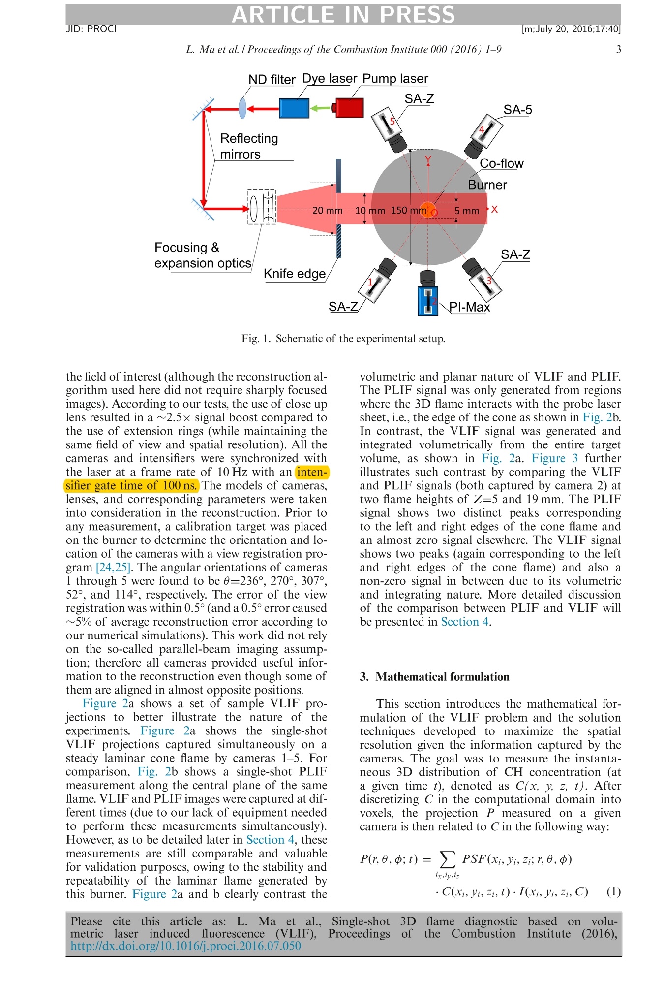
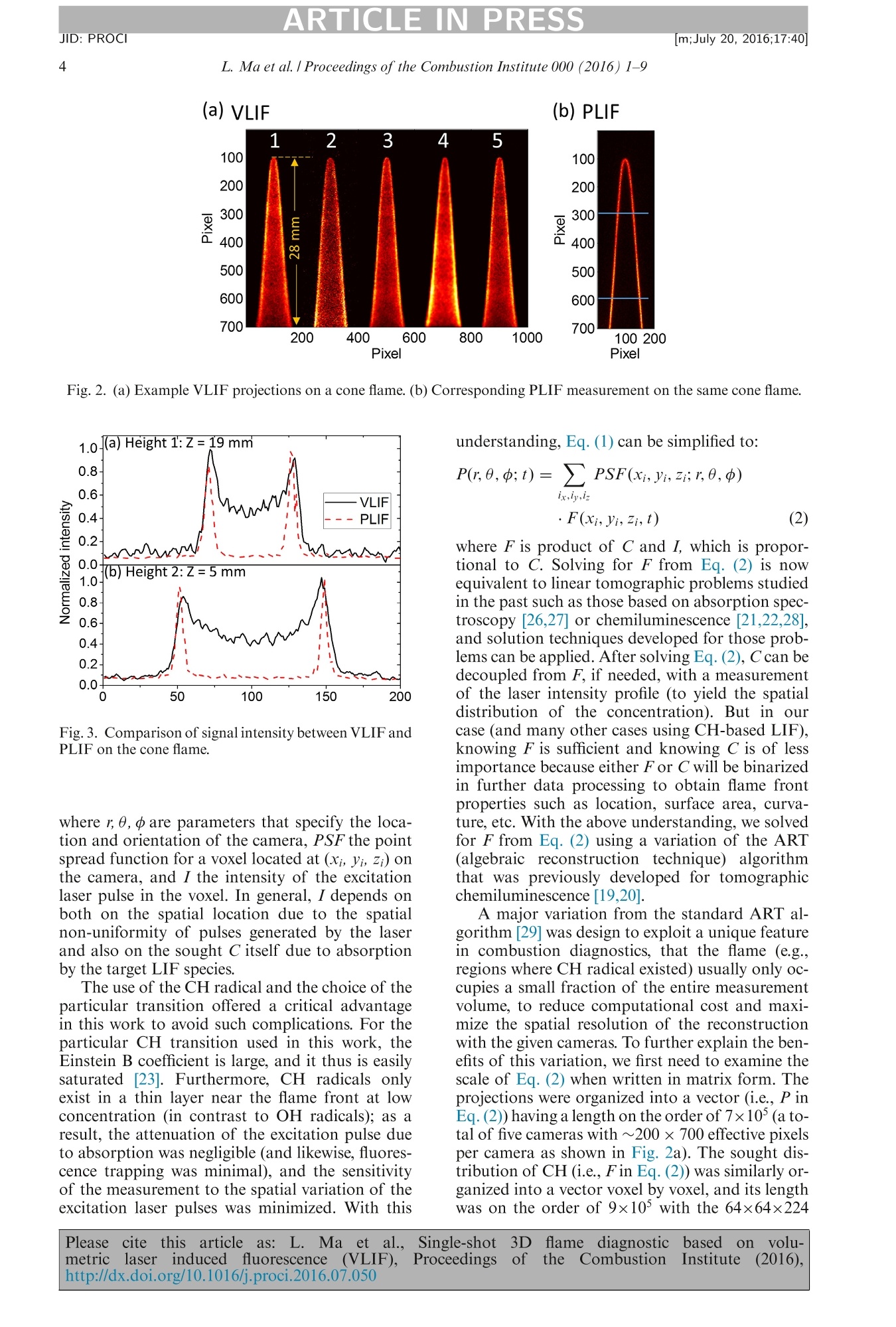
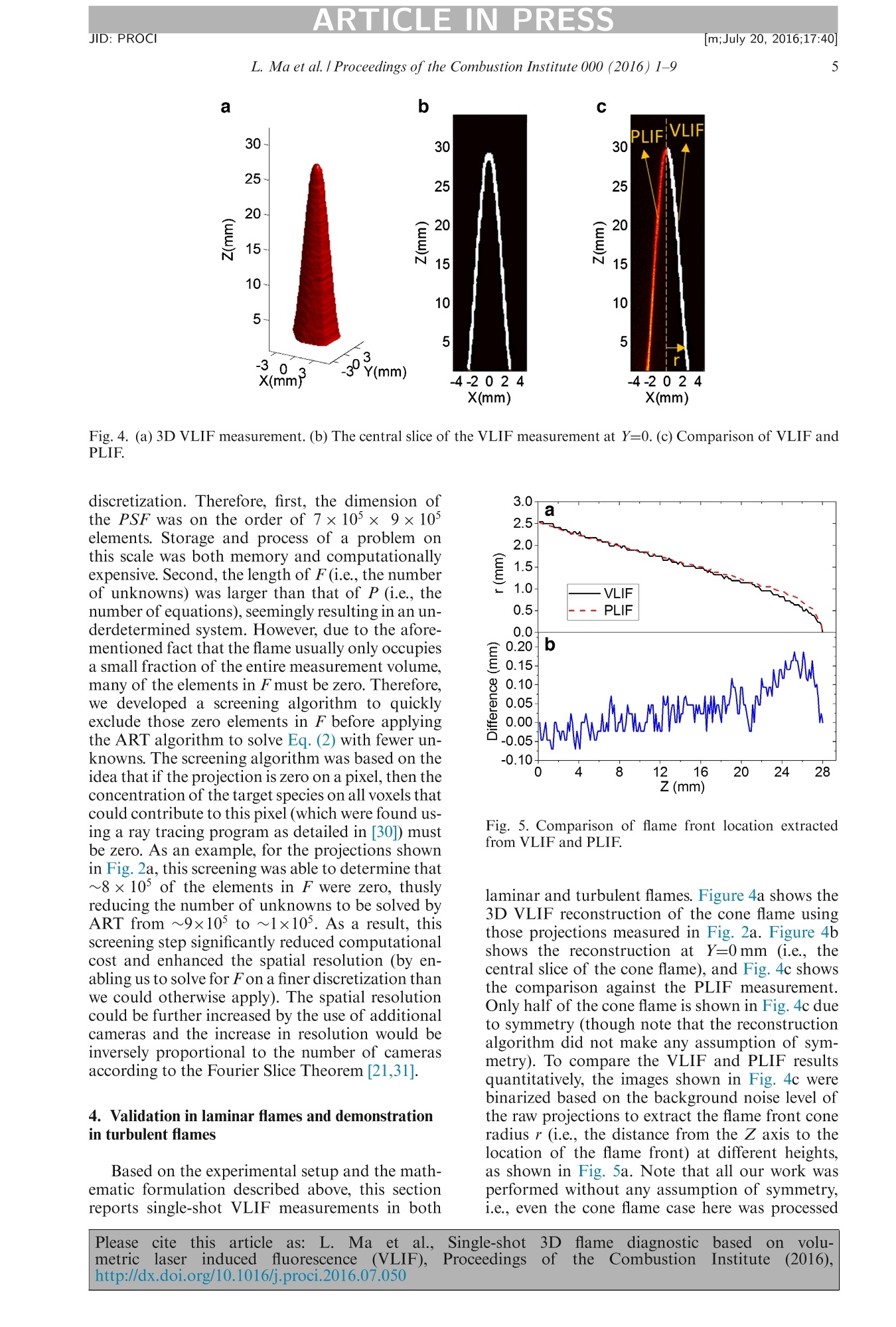
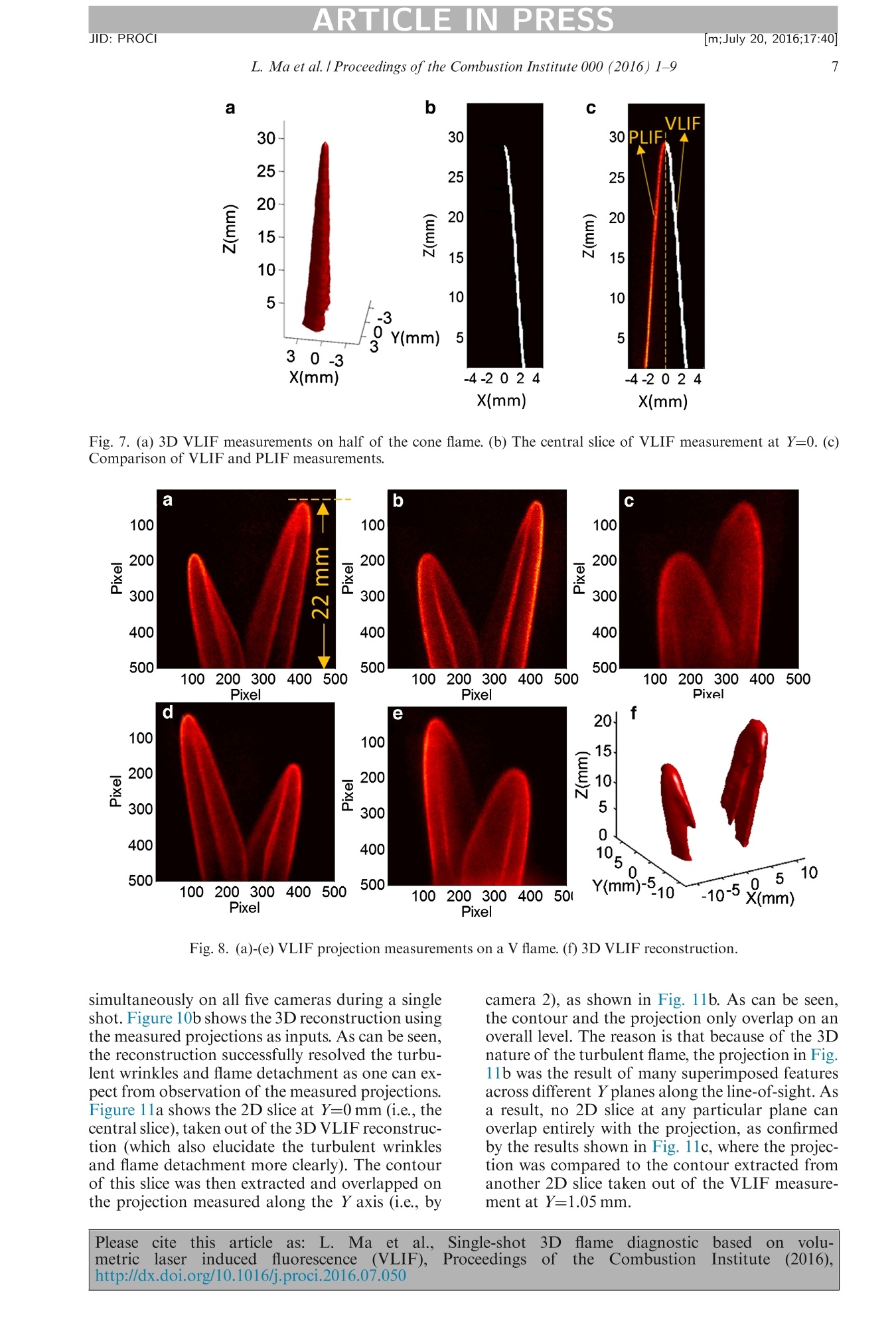
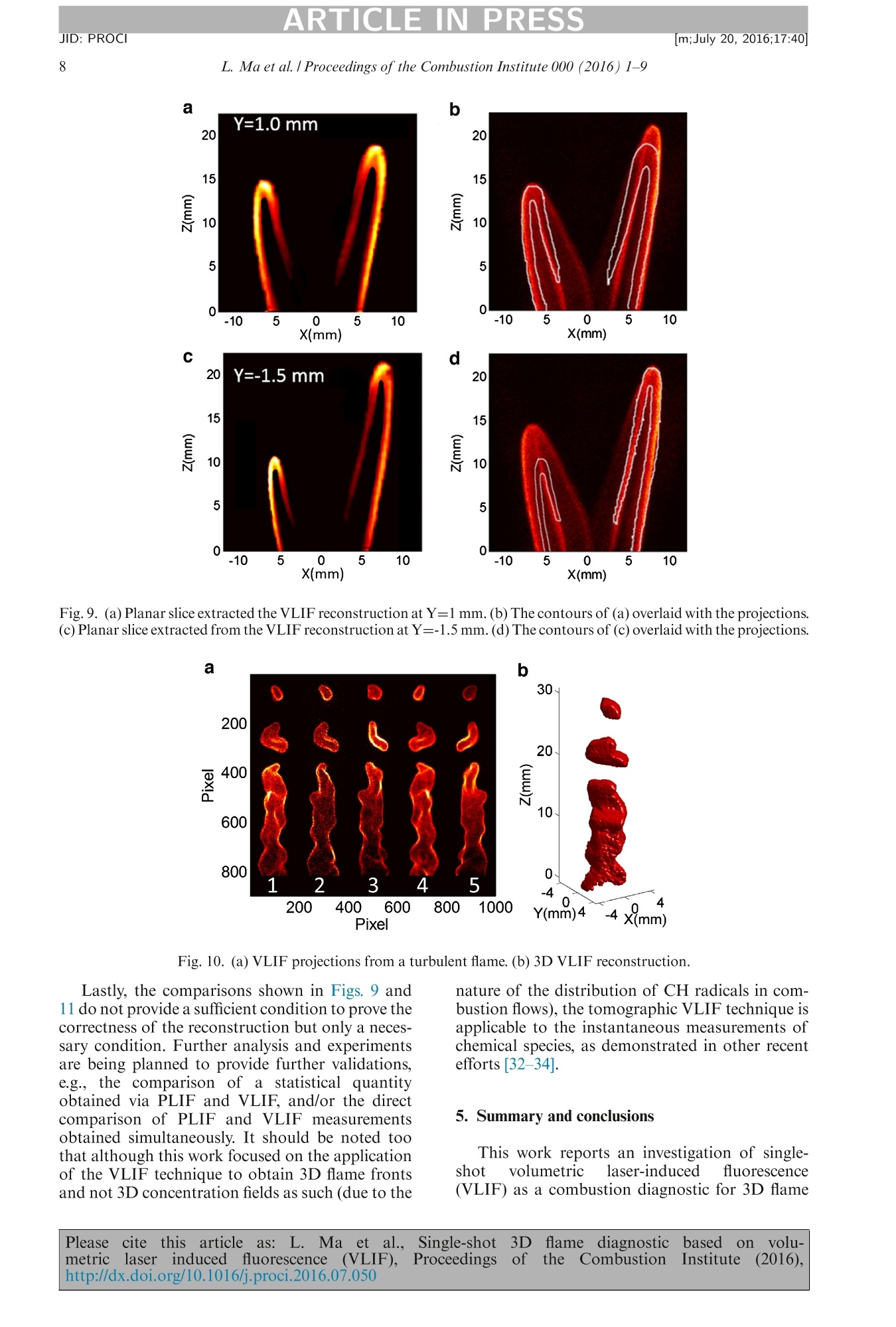
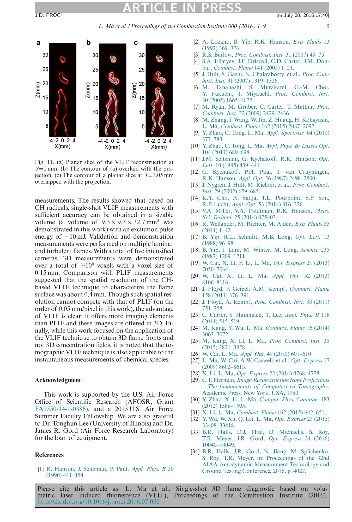
ARTICLE IN PRESSJID: PROCI[m;July 20, 2016;17:40]Available online at www.sciencedirect.comScienceDirectProceedings of the Combustion Institute 000 (2016) 1-9 ARTICLE IN PRESSJID: PROCI[m;July 20, 2016;17:40]2 1540-7489 C 2016 by The Combustion Institute. Published by Elsevier Inc. Proceedingsof theCombustionInstitute www.elsevier.com/locate/proci Single-shot 3D flame diagnostic based on volumetriclaser induced fluorescence (VLIF) Lin Ma ab*, Qingchun Lei , Jordan Ikeda , Wenjiang Xu a, Yue Wu a,Campbell D. Carter° a Department of Aerospace and Ocean Engineering, Virginia Tech, Blacksburg,r gV,A V2A4 24060, USA 'Department of Mechanical Engineering, Virginia Tech, Blacksburg, VA 24060, USA Air Force Research Laboratory,Wright-Patterson AFB, OH 45433, USA Received 13 November 2015; accepted 13 July 2016 Available online xxx Abstract We demonstrate single-shot three-dimensional (3D) flame measurements based on volumetric小 l2aser-induced fluorescence (VLIF). For this effort, the excitation laser beam was expanded into a“slab”with aheight of 40 mm and thickness of 10 mm to excite the CH radicals in the target flames. The volumetric LIFsignals were then simultaneously captured by five intensified cameras, and the images were fed into a to-mographic algorithm as inputs to obtain the 3D distribution of CH. The results show that single-shot 3Dmeasurements with sufficient accuracy can be obtained in a volume of 9.3×9.3×32.7 mm’ with an excita-tion pulse energy of ~10 mJ. With a total of five intensified cameras, 3D measurements were obtained with avoxel size of 0.15 mm over a total of 64× 64×224~10° voxels, which can be further improved by the use ofadditional cameras or advanced tomographic inversion techniques. Comparison with PLIF measurementssuggested that the spatial resolution of the CH-based VLIF technique to characterize the flame surface wasabout 0.4 mm. Measurements were first performed on stable laminar flames, for comparison and validationagainst PLIF, and then on turbulent jet flames, to illustrate the feasibility and accuracy of VLIF for instan-taneous 3D flame measurements and motivate further investigation. O 2016 by The Combustion Institute. Published by Elsevier Inc. Keywords: Volumetric laser induced fluorescence (VLIF); 3D diagnostics; Tomography * Corresponding author at: Department of Aerospaceand Ocean Engineering, McBryde Hall, Room 660A, 225Stanger St., Virginia Tech, Blacksburg, VA 24060, USA.Fax: +15402319632. E-mail address: linma@vt.edu (L. Ma). 1. Introduction After years of research and development, pla-nar laser-induced fluorescence (PLIF) has becomea powerful and indispensable tool for the study ofcombustion [1-3]. Based on different target species,either nascent intermediates such as the hydroxyl(OH) and methylidyne (CH) or seeded species suchas acetone, a range of key combustion properties Please cite this article as: L. Ma et al., Single-shot3Dflame diagnosticcbbasedonVvolu-metric laser inducedfluorescence (VLIF), Proceedingsofthe CombustionInstitute (2016),http://dx.doi.org/10.1016/j.proci.2016.07.050 L. Ma et al./ Proceedings of the Combustion Institute 000 (2016)1-9 such as the flame topography [4,5], reaction zonecharacteristics [6-8], mixture fraction [9,10], andtemperature [11] can be obtained from PLIF. How-ever,to resolve the inherent three-dimensional(3D)structures of turbulent flames, there is a strong mo-tivation to overcome the planar nature of PLIF sothat volumetric measurements can be enabled. One possible strategy to enable volumetricmeasurements involves a scanning PLIF method[12-18] wherein the probe laser sheet is rapidlyscanned across multiple spatial locations and thenPLIF images are recorded sequentially at theselocations, which are eventually compiled to forma 3D measurement. Even though the strategy isconceptually straightforward and has been demon-strated as early as the 1980s [12,17,18], obtaining3D measurements with sufficient temporal andspatial resolution remains challenging even withrecent advancement in high speed lasers (andthe corresponding camera and optomechanicaltechnologies). For example, recent measurementshave reported temporal resolution on the order of1 kHz, limited by the speed of the laser and scanner[13-16]. The spatial resolution, in principle, can becomparable to that of the PLIF in all three direc-tions. However, in practice, the spatial resolutionhas been limited to be on the order of 1 mm in thedirection of the scan due to experimental issues(e.g., the accuracy of the scanning mechanism andthe tradeoff between the spatial resolution and thesize of the measurement volume) [13-16]. This work therefore reports another approachto obtain 3D LIF measurements volumetricallyand instantaneously without the need of scan-ning (and correspondingly this approach is termedVLIF).The VLIF approach combines LIF with to-mography to enable 3D measurements, and single-shot measurements were demonstrated based onCH in a volume of 9.3×9.3×32.7mm’with avoxel size of 0.15 mm. The probe laser pulse wasexpanded to excite the target species volumetri-cally. The LIF photons emitted volumetrically werecaptured by five intensified cameras simultaneously(termed projections), and these projection mea-surements were used as the inputs to a tomographyalgorithm (as demonstrated in other types of vol-umetric diagnostics |[19-22])to reconstruct the 3Ddistribution of CH, which can then be used to cal-culate other flame properties in 3D. 2. Experimental arrangement Figure 1 schematically illustrates the experi-mental arrangement from the top view. The setupinvolved four major components: 1) a burner thatgenerated the target flame; 2) a laser system thatgenerated ns pulses to excite the CH radicals inthe flame; 3) focusing and expansion optics thatshaped the excitation beam into the desired dimen-sion to illuminate the desired measurement region volumetrically; and 4) five intensified camerasthat collected the VLIF projections from differentangular positions. The burner consisted ofa primary tube (5 mmID), from which issued chemically pure, premixedCH4 and air and a secondary tube (18 mm ID,con-centric with the inner tube) for stabilizing a low-speed, lean CH4-air pilot flame. The central tubeswere surrounded by a 150 mm ID air coflow witha flow rate 250 SLPM (standard liters per minute).To generate the stable laminar flames, the flow ratesof the fuel and air were set to be 0.352 and 2.41SLPM, respectively, producing a flame with equiv-alence ratio of +=1.4. To generate the turbulentflames, CH4 issued from the central tube at 1.11SLPM (and air flow rate was adjusted correspond-ingly so thatd=1.05). As shown in Fig. 1, the lasersystem consisted of a 10-Hzppump laser (Spectra-Physics GCR-170 Nd:YAG laser) and a dye laser(Lumonics HD300 dye laser) followed by an In-rad Autotracker III for frequency doubling the dyelaser beam. The pulse energy generated by the lasersystem was ~10mJ/pulse at the target excitationwavelength off3314.415 nm, and the pulse durationwas~10 ns.This wavelength was chosen follow-ing the work described in [23], to excite the over-lapped Q2(6) and Q2(2) transitions from the CHC2+-X2II(v=0,"=0) band. The excitation slabwas formed by a simple telescope, consisting of a-0.1-m focal length lens to expand the frequency-doubled dye beam followed a 1-mfocal length lensto collimate the beam. Two vertical knife edgeswere then used to clip the beam and control theithickness of the illumination slab. Based on the configuration of the burner andoptical path, a Cartesian coordinate system was es-tablished such that the origin was defined at the cen-ter of the burner, the X axis was defined along thepropagation direction of the laser, the Y axis wasdefined to be perpendicular to the propagation di-rection of the laser, and the Z axis was defined tobe along the direction of the flow. The VLIF signalswere captured by five intensified cameras, as shownin Fig. 1. Cameras 1, 3, and 5 were Photron SA-Zs (CMOS), and 4 was a Photron SA-5 (CMOS),all equipped with the same intensifier (LaVisionhighspeed IRO). Camera 2 was a PI-Max inten-sified (CCD) camera (Princeton Instruments). Allcameras were aligned in the X-Y plane (i.e., in acoplanar fashion), and therefore their orientationswere completely specified by 0, defined as the an-gle formed between the optical axis of each cameraand the positive X axis in the anti-clockwise direc-tion. All five cameras were equipped with the sameUV lens (Cerco with f=100 mm and f/2.8). A closeup lens (UV coated) was applied in front of the UVlens on each camera (with focal length=200 mm,300 mm, 200 mm, 250 mm, and 250 mm for cam-eras 1 through 5, respectively) to optimize the fieldof view and signal level. This setup resulted in adepth-of-field of ~5 mm, sufficiently large to cover Please cite this article as: L. Ma et al., Single-shot 3D flame diagnostic based on volu- metriclaser induced fluorescence (VLIF), Proceedingshttp://dx.doi.org/10.1016/j.proci.2016.07.050 of the Combustion 1 Institute (2016), Fig. 1. Schematic of the experimental setup. the field of interest (although the reconstruction al-gorithm used here did not require sharply focusedimages). According to our tests, the use of close uplens resulted in a ~2.5x signal boost compared tothe use of extension rings (while maintaining thesame field of view and spatial resolution). All thecameras and intensifiers were synchronized withthe laser at a frame rate of 10 Hz with aninten-sifier gate time of 100 ns.The models of cameras.lenses, and corresponding parameters were takeninto consideration in the reconstruction. Prior toany measurement, a calibration target was placedon the burner to determine the orientation and lo-cation of the cameras with a view registration pro-gram [24,25]. The angular orientations of cameras1 through 5 were found to be 0=236°,270°,307°,52°, and 114°, respectively. The error of the viewregistration was within 0.5°(and a 0.5° error caused~5% of average reconstruction error according toour numerical simulations). This work did not relyon the so-called parallel-beam imaging assump-tion; therefore all cameras provided useful infor-mation to the reconstruction even though some ofthem are aligned in almost opposite positions. volumetric and planar nature of VLIF and PLIF.The PLIF signal was only generated from regionswhere the 3D flame interacts with the probe lasersheet, i.e., the edge of the cone as shown in Fig. 2b.In contrast, the VLIF signal was generated andintegrated volumetrically from the entire targetvolume, as shown in Fig. 2a. Figure 3 furtherillustrates such contrast by comparing the VLIFand PLIF signals (both captured by camera 2) attwo flame heights of Z=5 and 19 mm. The PLIFsignal shows two distinct peaks correspondingto the left and right edges of the cone flame andan almost zero signal elsewhere. The VLIF signalshows two peaks (again corresponding to the leftand right edges of the cone flame) and also anon-zero signal in between due to its volumetricand integrating nature. More detailed discussionof the comparison between PLIF and VLIF willbe presented in Section 4. 3. Mathematical formulation This section introduces the mathematical for-mulation of the VLIF problem and the solutiontechniques developed to maximize the spatialresolution given the information captured by thecameras. The goal was to measure the instanta-neous 3D distribution of CH concentration (ata given time t), denoted as C(x, y,z, t). Afterdiscretizing C in the computational domain intovoxels, the projection P measured on a givencamera is then related to C in the following way: Please cite this article as: L. Ma et al., Single-shot 3 3D flame diagnostic based on volu- metriclaser induced fluorescence (VLIF), Proceedings of the Combustion Institute e(2016), http://dx.doi.org/10.1016/j.proci.2016.07.050 L. Ma et al. I Proceedings of the Combustion Institute 000 (2016)1-9 Fig. 2. (a) Example VLIF projections on a cone flame. (b) Corresponding PLIF measurement on the same cone flame. Fig. 3. Comparison of signal intensity between VLIF andPLIF on the cone flame. where r, 0,中 are parameters that specify the loca-tion and orientation of the camera, PSF the pointspread function for a voxel located at (xi, yi,zi) onthe camera, and I the intensity of the excitationlaser pulse in the voxel. In general, I depends onboth on the spatial location due to the spatialnon-uniformity of pulses generated by the laserand also on the sought C itself due to absorptionby the target LIF species. The use of the CH radical and the choice of theparticular transition offered a critical advantagein this work to avoid such complications. For theparticular CH transition used in this work, theEinstein B coefficient is large, and it thus is easilysaturated[23]. Furthermore, CH radicals onlyexist in a thin layer near the flame front at lowconcentration (in contrast to OH radicals); as aresult, the attenuation of the excitation pulse dueto absorption was negligible (and likewise, fluores-cence trapping was minimal), and the sensitivityof the measurement to the spatial variation of theexcitation laser pulses was minimized. With this where F is product of C and I, which is propor-tional to C. Solving for F from Eq. (2) is nowequivalent to linear tomographic problems studiedin the past such as those based on absorption spec-troscopy [26,27] or chemiluminescence [[21,22,28],and solution techniques developed for those prob-lems can be applied. After solving Eq.(2), C can bedecoupled from F, if needed, with a measurementof the laser intensity profile (to yield the spatialdistribution of the concentration). But in ourcase (and many other cases using CH-basedLIF),knowing F is sufficient and knowing C is of lessimportance because either F or C will be binarizedin further data processing to obtain flame frontproperties such as location, surface area, curva-ture, etc. With the above understanding, we solvedfor F from Eq. (2) using a variation of the ART(algebraic reconstruction technique) algorithmthat was previously developed for tomographicchemiluminescence [19,20]. Please cite this article as: L. Ma et al., Single-shot 3D flame diagnostic based on volu- metriclaser induced fluorescence (VLIF), Proceedingshttp://dx.doi.org/10.1016/j.proci.2016.07.050 of the Combustion 1 Institute (2016), discretization. Therefore, first, the dimension ofthe PSF was on the order of 7x105x 9×10fa1elements. Storage and process of a problem onthis scale was both memory and computationallyexpensive. Second,the length of F (i.e., the numberof unknowns) was larger than that of P (i.e., thenumber of equations), seemingly resulting in an un-derdetermined system. However, due to the afore-mentioned fact that the flame usually only occupiesa small fraction of the entire measurement volumemany of the elements in Fmust be zero. Therefore,we developed a screening algorithm to quicklyexclude those zero elements in F before applyingthe ART algorithm to solve Eq. (2) with fewer un-knowns. The screening algorithm was based on theidea that if the projection is zero on a pixel, then theconcentration of the target species on all voxels thatcould contribute to this pixel (which were found us-ing a ray tracing program as detailed in [30]) mustbe zero. As an example, for the projections shownin Fig. 2a, this screening was able to determine that~8×10⁵ of the elements in F were zero, thuslyreducing the number of unknowns to be solved byART from ~9×10 to ~1×10. As a result, thisscreening step significantly reduced computationalcost and enhanced the spatial resolution (by en-abling us to solve for F on a finer discretization thanwe could otherwise apply). The spatial resolutioncould be further increased by the use of additionalcameras and the increase in resolution would beinversely proportional to the number of camerasaccording to the Fourier Slice Theorem [21,31]. 4. Validation in laminar flames and demonstrationin turbulent flames Based on the experimental setup and the math-ematic formulation described above, this sectionreports single-shot VLIF measurements in both Fig. 5. Comparison of flame front location extractedfrom VLIF and PLIF. laminar and turbulent flames. Figure 4a shows the3D VLIF reconstruction of the cone flame usingthose projections measured in Fig. 2a. Figure 4bshows the reconstruction at Y=0 mm (i.e., thecentral slice of the cone flame), and Fig. 4c showsthe comparison against the PLIF measurement.Only half of the cone flame is shown in Fig. 4c dueto symmetry (though note that the reconstructionalgorithm did not make any assumption of sym-metry). To compare the VLIF and PLIF resultsquantitatively, the images shown in Fig. 4c werebinarized based on the background noise level ofthe raw projections to extract the flame front coneradius r (i.e., the distance from the Z axis to thelocation of the flame front) at different heights,as shown in Fig. 5a. Note that all our work wasperformed without any assumption of symmetry,i.e., even the cone flame case here was processed Please cite this article as: L. Ma et al., Single-shot 3 3D based flame diagnostic on volu- metriclaser induced fluorescence (VLIF), Proceedings of Institute the Combustion : (2016), http://dx.doi.org/10.1016/j.proci.2016.07.050 Fig. 6. VLIF projection measurements of half of thecone flame. without assuming any a priori information of itssymmetry. Figure. 5b then shows the differences in r de-termined from the PLIF and VLIF measurements.Here, we focus on two observations drawn fromthese data. First, the data in Fig. 5 show goodagreement between the PLIF and VLIF measure-ments, providing an experimental validation ofthe VLIF measurements. We extracted r from 200frames of the flame images, taken at different times,and the variation of r was within 0.02 mm, signif-icantly smaller than the difference seen in Fig. 5b.Second, the comparison between PLIF and VLIFalso illustrate the differences in their spatial resolu-tion. The pixel size of the PLIF image as shown inFig. 4c was about 0.05 mm/pixel, significantly finerthan the voxel size of the VLIF (defined as the di-mension of the measurement volume divided by thediscretization) of 0.15 mm/voxel.Comparison withPLIF measurements suggested that the spatial res-olution of the CH-based VLIF technique for flamesurface characterization was about 0.4 mm (esti-mated as the voxel size of 0.15 mm plus the rangeof difference seen in Fig. 5b). Therefore, with thecurrent status of the VLIF technique demonstratedin this work, it still cannot compete with PLIF interms of resolution in a plane, though the advan-tages of VLIF are also clear: it offers more imag-ing elements than PLIF (a total of ~9×10 VLIFvoxels in Fig. 4a versus ~1.4×10PLIF pixels inFig.2b) and these images are offered in 3D. Pro-jections from more views or improved algorithmsare needed to improve the spatial resolution of theVLIF technique. After the above fundamental study, we describetwo more experiments performed on stable lam-inar flames to further illustrate characteristics ofVLIF. The first experiment involved VLIF on halfof the cone flame, as shown in Figs. 6 and 7,to illustrate capability of VLIF to target an arbi-trary measurement region. In this experiment weadjusted location of one of the knife edges, sothat only half of the cone flame was illuminated. Figure 6 shows a set of VLIF projections; the dif-ference is apparent when compared to those shownin Fig. 2a, where the entire flame was illuminated.Figure 7a shows the 3D reconstruction, Fig. 7bshows the central slice at Y=0mm of the 3D re-construction, and Fig. 7c shows a direct compar-ison of the VLIF reconstruction against a PLIFmeasurement (again, only of half of the PLIF im-age is shown). This simple demonstration illustratesthe ability of VLIF to target an arbitrary regionin the flame, an important advantage compared toother volumetric techniques such as tomographicchemiluminescence (TC) [31]. The TC techniqueutilizes nascent flame emissions that are generatedthroughout the entire flame, and therefore it is prac-tically difficult to selectively target a specific por-tion of the flame. VLIF utilizes LIF photons thatare generated by the probe laser slab, and there-fore it is straightforward to target a selected re-gion in the flame by adjusting the slab location anddimensions. The second experiment involved VLIF on amore complicated V-shaped laminar flame, asshown in Fig. 8, created by placing a tungstenrod at the exit of the CH4-air jet. Figure 8a-dshows the projections, and Fig. 8e shows the 3Dreconstruction. As seen from Fig. 8e, the 3D re-construction correctly captured the overall V-flameshape,and the fact that one branch was taller thanthe other. Figure 9a shows a 2D slice of the VLIFreconstruction at Y=1 mm, to be compared withthe projection measured along the Y axis (i.e.,measured by camera 2), as shown in Fig. 9b. Tofacilitate the comparison, the contour of Fig. 9awas extracted via binarization and overlaid on theprojection shown in Fig. 9b. The idea behind thiscomparison was that even though the projectionwas line-of-sight averaged, some 3D informationmay still be inferred from salient features of theflame. and such information then can be used tovalidate the VLIF measurement. In the exampleshown in Fig. 9a and b, the plane at Y=1 mm waschosen because the left branch of the flame (i.e.,the shorter branch) was at its largest extent on thisplane, and this largest extent should be captured bythe projection because of its line-of-sight nature.This idea was confirmed by the close overlap seenin Fig. 9b between the contour and projectionon the left branch. Note that the contour andprojection did not overlap on the right branch,because at Y=1 mm, the right branch was not atits largest extent. The largest extent of the rightbranch occurred on the plane at Y=-1.5 mm, asshown in Fig. 9c. And as expected, the contour ex-tracted at Y=-1.5 mm overlapped closely with theprojection on the right branch, as shown in Fig. 9d.Figures 10 and 11 show a set of sample 3D VLIF measurements from a turbulent jet flame.The Reynolds number for the jet was 3355 (basedon jet diameter and jet-exit properties).Figure 10ashows a set of projection measurements captured Please cite this article as: L. Ma et al., Single-shot 3D flame diagnostic based con volu- metric laser induced fluorescence (VLIF), Proceedings of the Combustion Institute (2016), http://dx.doi.org/10.1016/j.proci.2016.07.050 Fig. 7. (a) 3D VLIF measurements on half of the cone flame. (b) The central slice of VLIF measurement at Y=0. (c)Comparison of VLIF and PLIF measurements. Fig. 8. (a)-(e) VLIF projection measurements on a V flame. (f) 3D VLIF reconstruction. simultaneously on all five cameras during a singleshot. Figure 10b shows the 3D reconstruction usingthe measured projections as inputs. As can be seen,the reconstruction successfully resolved the turbu-lent wrinkles and flame detachment as one can ex-pect from observation of the measured projections.Figure 11a shows the 2D slice at Y=0 mm (i.e., thecentral slice), taken out of the 3D VLIF reconstruc-tion (which also elucidate the turbulent wrinklesand flame detachment more clearly). The contourof this slice was then extracted and overlapped onthe projection measured along the Y axis (i.e., by camera 2), as shown in Fig. 11b. As can be seen,the contour and the projection only overlap on anoverall level. The reason is that because of the 3Dnature of the turbulent flame, the projection in Fig.11b was the result of many superimposed featuresacross different Y planes along the line-of-sight. Asa result, no 2D slice at any particular plane canoverlap entirely with the projection, as confirmedby the results shown in Fig.11c, where the projec-tion was compared to the contour extracted fromanother 2D slice taken out of the VLIF measure-ment at Y=1.05mm. Please cite this article as: L. Ma et al., Single-shot 3D flame diagnostic on volu- c based metriclaser induced fluorescence (VLIF), Proceedings of the Combustion e(2016), Institute http://dx.doi.org/10.1016/j.proci.2016.07.050 Fig.9. (a) Planar slice extracted the VLIF reconstruction at Y=1 mm.(b) The contours of (a) overlaid with the projections.(c) Planar slice extracted from the VLIF reconstruction at Y=-1.5 mm. (d) The contours of (c) overlaid with the projections. Fig. 10. (a) VLIF projections from a turbulent flame. (b) 3D VLIF reconstruction. Lastly, the comparisons shown in Figs. 9 and11 do not provide a sufficient condition to prove thecorrectness of the reconstruction but only a neces-sary condition. Further analysis and experimentsare being planned to provide further validations,e.g., the comparison of a statistical quantityobtained via PLIF and VLIF, and/or the directcomparison of PLIF and VLIF measurementsobtained simultaneously. It should be noted toothat although this work focused on the applicationof the VLIF technique to obtain 3D flame frontsand not 3D concentration fields as such (due to the nature of the distribution of CH radicals in com-bustion flows), the tomographic VLIF technique isapplicable to the instantaneous measurements ofchemical species, as demonstrated in other recentefforts [32-34]. 5. Summary and conclusions This work reports an investigation of single-shot volumetric laser-inducedfluorescence(VLIF) as a combustion diagnostic for 3D flame Please cite this article as: L. Ma et al., Single-shot 3D flame diagnostic bbased con volu- metric laser induced fluorescence (VLIF), Proceedings of the Combustion Institute (2016), http://dx.doi.org/10.1016/j.proci.2016.07.050 Fig. 11. (a) Planar slice of the VLIF reconstruction atY=0 mm. (b) The contour of (a) overlaid with the pro-jection. (c) The contour of a planar slice at Y=1.05 mmoverlapped with the projection. measurements. The results showed that based onCH radicals, single-shot VLIF measurements withsufficient accuracy can be obtained in a sizablevolume (a volume of 9.3×9.3×32.7mm’ wasdemonstrated in this work) with an excitation pulseenergy of ~10 mJ. Validation and demonstrationmeasurements were performed on multiple laminarand turbulent flames. With a total of five intensifiedcameras, 3D measurements were demonstratedover a total of ~10° voxels with a voxel size of0.15 mm. Comparison with PLIF measurementssuggested that the spatial resolution of the CH-based VLIF technique to characterize the flamesurface was about 0.4 mm. Though such spatial res-olution cannot compete with that of PLIF (on theorder of 0.05 mm/pixel in this work), the advantageof VLIF is clear: it offers more imaging elementsthan PLIF and these images are offered in 3D. Fi-nally, while this work focused on the application ofthe VLIF technique to obtain 3D flame fronts andnot 3D concentration fields, it is noted that the to-mographic VLIF technique is also applicable to theinstantaneous measurements of chemical species. Acknowledgment This work is supported by the U.S. Air ForceOffice of Scientific Research (AFOSR, GrantFA9550-14-1-0386), and a 2015U.S. Air ForceSummer Faculty Fellowship. We are also gratefulto Dr. Tonghun Lee (University of Illinois) and Dr.James R. Gord (Air Force Research Laboratory)for the loan of equipment. ( References ) ( [1] R. H anson, J. Seitzman , P. Paul, Appl . Phys . B 50(1990)441-454. ) ( [2] A . L ozano, B. Yip, R.K. Hanson, E xp. Fluids 1 3(1992) 369 - 376. ) ( R .S. B a rlow, Proc. C ombust. I n st. 3 1 (2007)49-7 5 . ) ( 34 ] S.A. Filatyev, J. F . D r iscoll, C .D . C arter , J .M . Don-bar, Combust. Flame 141 (2005)1- 2 1. ) ( [5] |J . H ult, S . Gashi, N. Chakraborty, e t al., P roc. Com-bust. Inst . 31 (2007)1319- 1 326. ) ( 6] 1 M. T anahashi , S. N Murakami.G.-M. C hoi. Y. Fukuchi, T. M iyauchi, P roc. C ombust. I nst. 30 (2005) 1665 - 1672. ) ( [7] M. R yan, M . Gruber, C. Carter, T. M athu r , Proc.Combust. I nst. 32 (2009) 2429 - 2436. ) ( [8]| M. Zhang,J.Wang, W. Jin, Z. Huang,H . K obayashi,L. Ma, Combust. Flame 162 (2015) 2087-2097. ) ( [9]] Y. Zhao, C. Tong, L. Ma, A ppl. Spectrosc . 64 (2010)377-383. ) ( [10]| Y . Zhao, C . T ong, L . M a , Appl. Ph y s. B: La s ers Opt.104(2011)689- 6 98. ) ( [11] J.M. Seitzman, G. Kychakoff, R.K. Hanson, Opt.Lett. 10 (1985) 439-441. ) ( [12] G . Kychakoff, P .H. P aul,, I. van C ruyningen, R .K. Hanson, App l. Opt. 2 6 (1987) 2 498- 2 500. ) ( [13] J.N yg ren, J. Hult, M. R ichte r , et al. , Pro c . Combust.Inst. 29 (2002)679-685. ) ( [14]] K . Y. Cho, A. S atija, T .L. Pourpoint, S . F. Son, R .P. L ucht, Appl. O pt. 5 3 (2014) 316-3 2 6. ) ( [15] V.A. Miller , V.A . Troutman, R.K. Hanson, M eas.Sci. Technol. 25 (2014) 075403. ) ( ] R. Wellander, M. Richter, M. A l den, Exp. F lu ids 55(2014)1-1 2 . ) ( ] B. Y i p, R.L. Schmitt , M. B . L ong, Opt. L e tt. 1 3(1988)96- 9 8. ) ( | B. Yip , J. Lam, M. Winter, M . L o ng, Science 235(198 7)1 209- 1 211. ) ( | W. Cai, X. L i , F. Li, L. Ma, Opt. E x press 21 (2 0 13)7050-7064. ) ( | W. Cai, X. 1L i, L . M a, Appl. O pt. 5 2 (2013)8106-8116. ) ( | J . Floyd , P . Geipe l , A .M . Kempf, C o mbust. F lame158 (2011 ) 376- 3 91. ) ( | J . Floyd , A. Kempf, Proc. C ombust. Inst. 3 3 ( 2 011)751 - 758. ) ( ] C. Carter,S. Ham m ack, T. L e e, A p p l. P h ys. B 116 (2014)515-519. ) ( M. Kang, Y . Wu, L . Ma, Combust. Flame16 (2014)3063-3072. ) ( | M. K ang, X. Li , L . M a, P r oc. C ombust. Inst. 35(201 5) 3821 - 3 828. ) ( W. Cai, L. Ma, A ppl. Opt. 49 (2010) 601-610. ) ( | L . Ma, W . Cai, A. W. Caswell, et al., Opt. Express 1 7 (2009)8602-8613. ) ( X . Li, L. M a ,Opt. Express 22 (2014)4768-4778. ) ( [29] ] C.T. Herman, I mage Reconstruct i on from Projections - T h e f undamentals o f C omputerized Tomography,Academic P ress, New York,U S A, 1 980. ) ( [30]] Y. Zhao,X. L i, L. Ma, Comput. Phys. Commun. 183(2012) 1 588-1595. ) ( X . Li, L. Ma , C o mbust. Flame 16 2 (2015) 642-651. ) ( | Y. Wu, W. Xu, Q. L ei, L. Ma, O pt. Express 23 (2015)33408-33418. ) ( B.R. H alls. D .J . Thul. D. M ichaelis. S. Roy. T.R. Me y er, J .R. Gord, O pt. E xpress 24 ( 2 016)10040-10049. ) ( [34] ] B.R . Halls , J .R . Gord, N. Jiang, M. Splichenko,S. Ro y ,T.R. M e y er , in: P r oceedings of t h e 3 2 ndAIAA Aerodynamic Mea s urement Technology and Ground Testing Conference, 2 016, p . 4027. ) Please cite this article as: L. Ma et al., Single-shot 3D flame diagnostic based on volu- metriclaser induced fluorescence (VLIF), Proceedings of the Combustion Institute : (2016), http://dx.doi.org/10.1016/j.proci.2016.07.050 We demonstrate single-shot three-dimensional (3D) flame measurements based on volumetric laser-induced fluorescence (VLIF). For this effort, the excitation laser beam was expanded into a “slab”with aheight of 40 mm and thickness of 10 mm to excite the CH radicals in the target flames. The volumetric LIFsignals were then simultaneously captured by five intensified cameras, and the images were fed into a tomographicalgorithm as inputs to obtain the 3D distribution of CH. The results show that single-shot 3Dmeasurements with sufficient accuracy can be obtained in a volume of 9.3 × 9.3 × 32.7 mm 3 with an excita-tion pulse energy of ∼10 mJ. With a total of fiv e intensified cameras, 3D measurements were obtained with avoxel size of 0.15 mm over a total of 64 × 64 × 224 ≈10 6 voxels, which can be further improved by the use ofadditional cameras or advanced tomographic inversion techniques. Comparison with PLIF measurementssuggested that the spatial resolution of the CH-based VLIF technique to characterize the flame surface wasabout 0.4 mm. Measurements were first performed on stable laminar flames, for comparison and validationagainst PLIF, and then on turbulent jet flames, to illustrate the feasibility and accuracy of VLIF for instantaneous3D flame measurements and motivate further investigation.
确定

还剩7页未读,是否继续阅读?

产品配置单


北京欧兰科技发展有限公司为您提供《火焰中CH自由基荧光检测方案(CCD相机)》,该方案主要用于其他中CH自由基荧光检测,参考标准--,《火焰中CH自由基荧光检测方案(CCD相机)》用到的仪器有LaVision HighSpeedStar 高帧频相机、德国LaVision PIV/PLIF粒子成像测速场仪
推荐专场


相关方案
更多
该厂商其他方案
更多