


The test rig employed in this study consisted of a high-pressure cylindrical steel
vessel with a length of 1.8 m and an internal diameter of 0.28 m. Visual inspection
and accessibility of the reactor assembly was achieved via a 50 mm diameter quartz
window at the rear flange of the vessel and two 350 mm long and 50 mm high
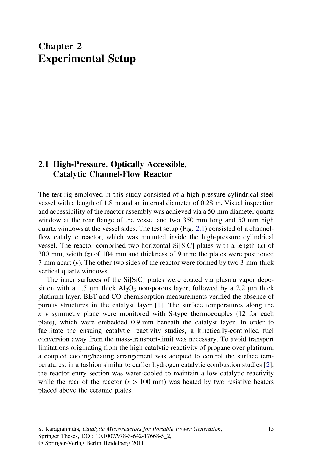
quartz windows at the vessel sides. The test setup (Fig. 2.1) consisted of a channelflow
catalytic reactor, which was mounted inside the high-pressure cylindrical
vessel. The reactor comprised two horizontal Si[SiC] plates with a length (x) of
300 mm, width (z) of 104 mm and thickness of 9 mm; the plates were positioned
7 mm apart (y). The other two sides of the reactor were formed by two 3-mm-thick
vertical quartz windows.
方案详情

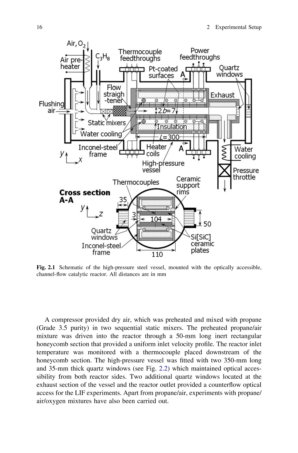
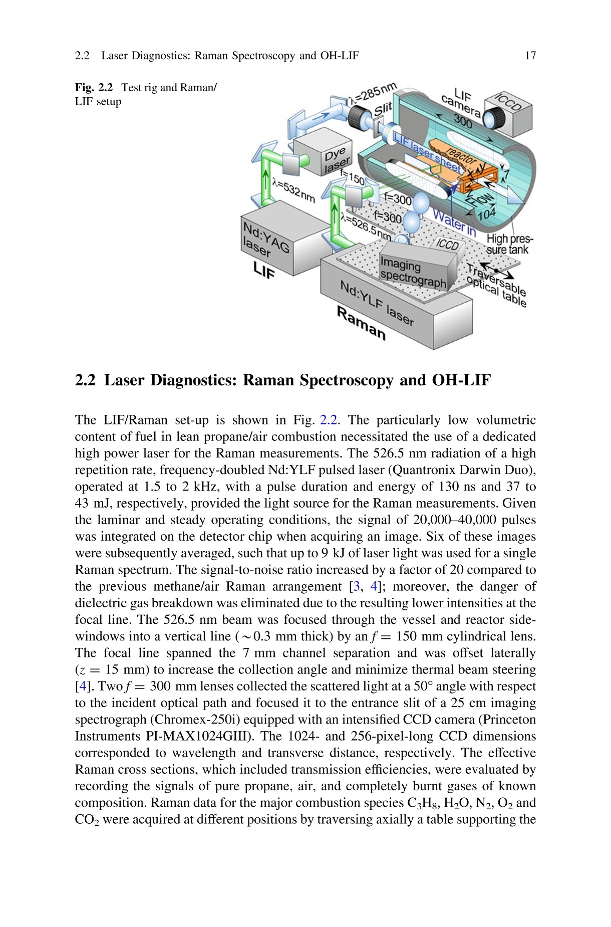
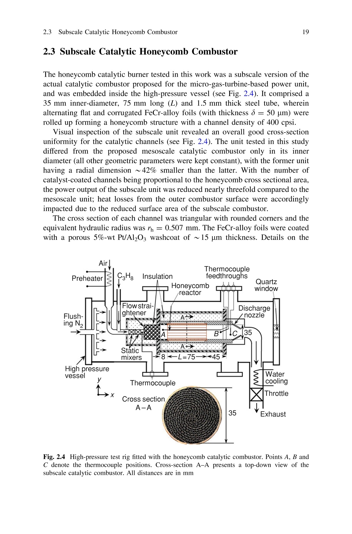
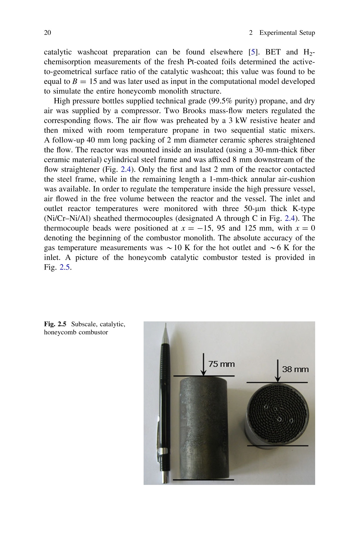
162 Experimental Setup 172.2 Laser Diagnostics: Raman Spectroscopy and OH-LIF 15S. Karagiannidis, Catalytic Microreactors for Portable Power Generation,Springer Theses, DOI: 10.1007/978-3-642-17668-5_2,@ Springer-Verlag Berlin Heidelberg 2011 Springer Theses Bearbeitet von 1. Auflage 2011. Buch. xvi, 112 S. Hardcover |SBN 978 3 642 17667 8 Symeon Karagiannidis Format (BxL): 15,5x23,5 cm Gewicht: 364 g Weitere Fachgebiete>Technik >Energietechnik, Elektrotechnik Energieumwandlung.Energiespeicherung Zu Inhaltsverzeichnis schnell und portofrei erhaltlich bei DIE FACHBUCHHANDLUNG Die Online-Fachbuchhandlung beck-shop.de ist spezialisiert auf Fachbucher, insbesondere Recht, Steuern und Wirtschaft.Im Sortiment finden Sie alle Medien (Bucher, Zeitschriften, CDs, eBooks, etc.) aller Verlage. Erganzt wird das Programmdurch Services wie Neuerscheinungsdienst oder Zusammenstellungen von Buchern zu Sonderpreisen. Der Shop fuihrt mehrals 8 Millionen Produkte. Chapter 2Experimental Setup 2.1 High-Pressure, Optically Accessible,Catalytic Channel-Flow Reactor The test rig employed in this study consisted of a high-pressure cylindrical steelvessel with a length of 1.8 m and an internal diameter of 0.28 m. Visual inspectionand accessibility of the reactor assembly was achieved via a 50 mm diameter quartzwindow at the rear flange of the vessel and two 350 mm long and 50 mm highquartz windows at the vessel sides. The test setup (Fig. 2.1) consisted of a channel-flow catalytic reactor, which was mounted inside the high-pressure cylindricalvessel. The reactor comprised two horizontal Si[SiC] plates with a length (x) of300 mm, width (z) of 104 mm and thickness of 9 mm; the plates were positioned7 mm apart (y). The other two sides of the reactor were formed by two 3-mm-thickvertical quartz windows. The inner surfaces of the Si[SiC] plates were coated via plasma vapor depo-sition with a 1.5 pm thick Al203 non-porous layer, followed by a 2.2 um thickplatinum layer. BET and CO-chemisorption measurements verified the absence ofporous structures in the catalyst layer [1]. The surface temperatures along thex-y symmetry plane were monitored with S-type thermocouples (12 for eachplate), which were embedded 0.9 mm beneath the catalyst layer. In order tofacilitate the ensuing catalytic reactivity studies, a kinetically-controlled fuelconversion away from the mass-transport-limit was necessary. To avoid transportlimitations originating from the high catalytic reactivity of propane over platinum,a coupled cooling/heating arrangement was adopted to control the surface tem-peratures: in a fashion similar to earlier hydrogen catalytic combustion studies [2],the reactor entry section was water-cooled to maintain a low catalytic reactivitywhile the rear of the reactor (x > 100 mm) was heated by two resistive heatersplaced above the ceramic plates. Fig. 2.1SSchematic of the high-pressure steel vessel, mounted with the optically accessible,channel-flow catalytic reactor. All distances are in mm A compressor provided dry air, which was preheated and mixed with propane(Grade 3.5 purity) in two sequential static mixers. The preheated propane/airmixture was driven into the reactor through a 50-mm long inert rectangularhoneycomb section that provided a uniform inlet velocity profile. The reactor inlettemperature was monitored with a thermocouple placed downstream of thehoneycomb section. The high-pressure vessel was fitted with two 350-mm longand 35-mm thick quartz windows (see Fig. 2.2) which maintained optical acces-sibility from both reactor sides. Two additional quartz windows located at theexhaust section of the vessel and the reactor outlet provided a counterflow opticalaccess for the LIF experiments. Apart from propane/air, experiments with propane/air/oxygen mixtures have also been carried out. Fig. 2.2 Test rig and Raman/ LIF setup 2.2 Laser Diagnostics: Raman Spectroscopy and OH-LIF The LIF/Raman set-up is shown in Fig. 2.2. The particularly low volumetriccontent of fuel in lean propane/air combustion necessitated the use of a dedicatedhigh power laser for the Raman measurements. The 526.5 nm radiation of a highrepetition rate, frequency-doubled Nd:YLF pulsed laser (Quantronix Darwin Duo),operated at 1.5 to 2 kHz, with a pulse duration and energy of 130 ns and 37 to43 mJ, respectively, provided the light source for the Raman measurements. Giventhe laminar and steady operating conditions, the signal of 20,000-40,000 pulseswas integrated on the detector chip when acquiring an image. Six of these imageswere subsequently averaged, such that up to 9 kJ of laser light was used for a singleRaman spectrum. The signal-to-noise ratio increased by a factor of 20 compared tothe previous methane/air Raman arrangement [3, 4]; moreover, the danger ofdielectric gas breakdown was eliminated due to the resulting lower intensities at thefocal line. The 526.5 nm beam was focused through the vessel and reactor side-windows into a vertical line (~0.3 mm thick) by an f= 150 mm cylindrical lens.The focal line spanned the 7 mm channel separation and was offset laterally(z =15 mm) to increase the collection angle and minimize thermal beam steering[4]. Twof= 300 mm lenses collected the scattered light at a 50° angle with respectto the incident optical path and focused it to the entrance slit of a 25 cm imagingspectrograph (Chromex-250i) equipped with an intensified CCD camera (PrincetonInstruments PI-MAX1024GIII). The 1024- and 256-pixel-long CCD dimensionscorresponded to wavelength and transverse distance, respectively. The effectiveRaman cross sections, which included transmission efficiencies,were evaluated byrecording the signals of pure propane, air, and completely burnt gases of knowncomposition. Raman data for the major combustion species C3Hg, H2O,N2,O2 andCO2 were acquired at different positions by traversing axially a table supporting the sending and collecting optics and also the Nd:YLF laser (Fig. 2.2). The 250-pixel-long 7 mm channel height was binned to 63 pixels. For the OH-LIF, the 532 nm radiation of a frequency-doubled Nd:YAG laser(Quantel TDL90 NBP2UVT3) pumped a tunable dye laser (Quantel TDL90);its frequency-doubled radiation (285 nm) had a pulse energy of 0.5 mJ,low enoughto avoid saturation of the A(v =1)← X(v'=0) transition. The 285 nm beam wastransformed into a laser sheet by a cylindrical lens telescope and a 1 mm slit mask,which propagated counterflow, along the x-ysymmetry plane (Fig. 2.2). Thefluorescence of both (1-1) and (0-0) transitions at 308 and 314 nm, respectively, wascollected at 90°(through the reactor and vessel side-windows) with an intensifiedCCD camera (LaVision Imager Compact HiRes IRO, 1,392 ×1,024 pixels binnedto 696 × 512). A 120×7 mmsection of the combustor was imaged on a 600 ×34pixelCCD-area. The camera was traversed axially to map the 300 mmreactor extent;at each measuring location 400 images were averaged. A picture of the actual test rigmounted with optics and Raman set-up is provided in Fig. 2.3, along with pictures ofthe platinum-coated plates, complete with the embedded thermocouples. Fig. 2.3 Optics, spectrograph and Nd:YLFlaser mounted on the test rig(a), and side view of the high-pressure test rig (b), alongwith pictures of the platinum-coated and thermocouple-fitted sides of a reactor plate 2.3 Subscale Catalytic Honeycomb Combustor The honeycomb catalytic burner tested in this work was a subscale version of theactual catalytic combustor proposed for the micro-gas-turbine-based power unit,and was embedded inside the high-pressure vessel (see Fig. 2.4). It comprised a35 mm inner-diameter, 75 mm long (L) and 1.5 mm thick steel tube, whereinalternating flat and corrugated FeCr-alloy foils (with thickness ;= 50 um) wererolled up forming a honeycomb structure with a channel density of 400 cpsi. Visual inspection of the subscale unit revealed an overall good cross-sectionuniformity for the catalytic channels (see Fig. 2.4). The unit tested in this studydiffered from the proposed mesoscale catalytic combustor only in its innerdiameter (all other geometric parameters were kept constant), with the former unithaving a radial dimension ~42% smaller than the latter. With the number ofcatalyst-coated channels being proportional to the honeycomb cross sectional area,the power output of the subscale unit was reduced nearly threefold compared to themesoscale unit; heat losses from the outer combustor surface were accordinglyimpacted due to the reduced surface area of the subscale combustor. The cross section of each channel was triangular with rounded corners and theequivalent hydraulic radius was th =0.507 mm. The FeCr-alloy foils were coatedwith a porous 5%-wt Pt/Al2O washcoat of~15 pm thickness. Details on the Fig. 2.4 High-pressure test rig fitted with the honeycomb catalytic combustor. Points A, B andC denote the thermocouple positions. Cross-section A-A presents a top-down view of thesubscale catalytic combustor. All distances are in mm catalytic washcoat preparation can be found elsewhere [5]. BET and H2-chemisorption measurements of the fresh Pt-coated foils determined the active-to-geometrical surface ratio of the catalytic washcoat; this value was found to beequal to B= 15 and was later used as input in the computational model developedto simulate the entire honeycomb monolith structure. High pressure bottles supplied technical grade (99.5% purity) propane, and dryair was supplied by a compressor. Two Brooks mass-flow meters regulated thecorresponding flows. The air flow was preheated by a 3 kW resistive heater andthen mixed with room temperature propane in two sequential static mixers.A follow-up 40 mm long packing of 2 mm diameter ceramic spheres straightenedthe flow.The reactor was mounted inside an insulated (using a 30-mm-thick fiberceramic material) cylindrical steel frame and was affixed 8 mm downstream of theflow straightener (Fig. 2.4). Only the first and last 2 mm of the reactor contactedthe steel frame, while in the remaining length a 1-mm-thick annular air-cushionwas available. In order to regulate the temperature inside the high pressure vessel,air flowed in the free volume between the reactor and the vessel. The inlet andoutlet reactor temperatures were monitored with three 50-um thick K-type(Ni/Cr-Ni/Al) sheathed thermocouples (designated A through C in Fig. 2.4). Thethermocouple beads were positioned at x=-15, 95 and 125 mm, with x=0denoting the beginning of the combustor monolith. The absolute accuracy of thegas temperature measurements was ~ 10 K for the hot outlet and ~6 K for theinlet. A picture of the honeycomb catalytic combustor tested is provided inFig. 2.5. Fig.2.5 Subscale, catalytic,honeycomb combustor References 1. Reinke M, Mantzaras J, Bombach R, Schenker S, Inauen A (2005) Gas-phase chemistry incatalytic combustion of methane/air mixtures over platinum at pressures of 1 bar to 16 bar.Combust Flame 141:448-468 2. Appel C, Mantzaras J, Schaeren R, Bombach R, Inauen A, Kaeppeli B, Hemmerling B,Stampanoni A (2002) An experimental and numerical investigation of homogeneous ignitionin catalytically stabilized combustion of hydrogen/air mixtures over platinum. Combust Flame128:340-368 3. Reinke M, Mantzaras J, Schaeren R, Bombach R, Inauen A, Schenker S (2004) High-pressurecatalytic combustion of methane over platinum: in situ experiments and detailed numericalpredictions. Combust Flame 136:217-240 4. Reinke M, Mantzaras J, Schaeren R, Bombach R, Inauen A, Schenker S (2005) Homogeneousignition of CH4/air and H2O-and CO2-diluted CH4/O2 mixtures over platinum; an experimentaland numerical investigation at pressures up to 16 bar. Proc Combust Inst 30:2519-2527 5. Eriksson S, Wolf M, Schneider A, Mantzaras J, Raimondi F, Boutonnet M, Jaras S (2006)Fuel-rich catalytic combustion of methane in zero emissions power generation processes. CatalToday 117:447-453
确定


还剩6页未读,是否继续阅读?

产品配置单

北京欧兰科技发展有限公司为您提供《便携式发电机的催化微反应器中拉曼,LIF信号检测方案(流量计)》,该方案主要用于其他中拉曼,LIF信号检测,参考标准--,《便携式发电机的催化微反应器中拉曼,LIF信号检测方案(流量计)》用到的仪器有PLIF平面激光诱导荧光火焰燃烧检测系统、Ekspla CARS 相干反斯托克斯拉曼显微光谱仪
推荐专场


相关方案
更多
该厂商其他方案
更多