


方案详情
文
High-level Nitrogen oxides (NOx) released to the atmosphere cause health and environmental hazards. Conventional power plants are required to have NOx emission control systems to abide by local environmental regulations. Com-mon post-combustion techniques include selective non-catalytic reduction (SNCR) or selective catalytic reduction (SCR) techniques. SNCR is a proven technology that can be implemented virtually without affecting existing indus-trial operations with low capital cost. SNCR is a method involving either aqueous ammonia or urea as the reagent injected into flue gas in the boiler/furnace within specific temperature range. This method commonly reduces the emission of NOx by 30-50%. However, high reductions can be achieved by system optimization. Placement within the proper temperature window, distribution within the cross section and residence time of reagent significantly in-fluence performance of an SNCR system. Therefore, spray lance and nozzle design is crucial for assurance of oper-ating efficiency and ammonia utilization.
In this paper, an SNCR system in a circulating fluidized bed (CFB) boiler was studied with using Computational Fluid Dynamics (CFD) simulations, as it relates to spray technology. The simulation solves Navier-Stokes equa-tions with heat and mass transfer using ANSYS Fluent SNCR model with Lagrangian multiphase models and spe-cies transport model. CFD was used to diagnose the gas phase behavior and thermal distribution, to determine opti-mal spray placement and maximum penetration. The focus of this work was the parameters of the injection, which were determined based on test data acquired through in-house laboratory equipment. Temperature profile, pollutant reduction, ammonia slippage and wall impingement were used from the CFD results to assist determining the best spray design to achieve the greatest efficiency.
方案详情

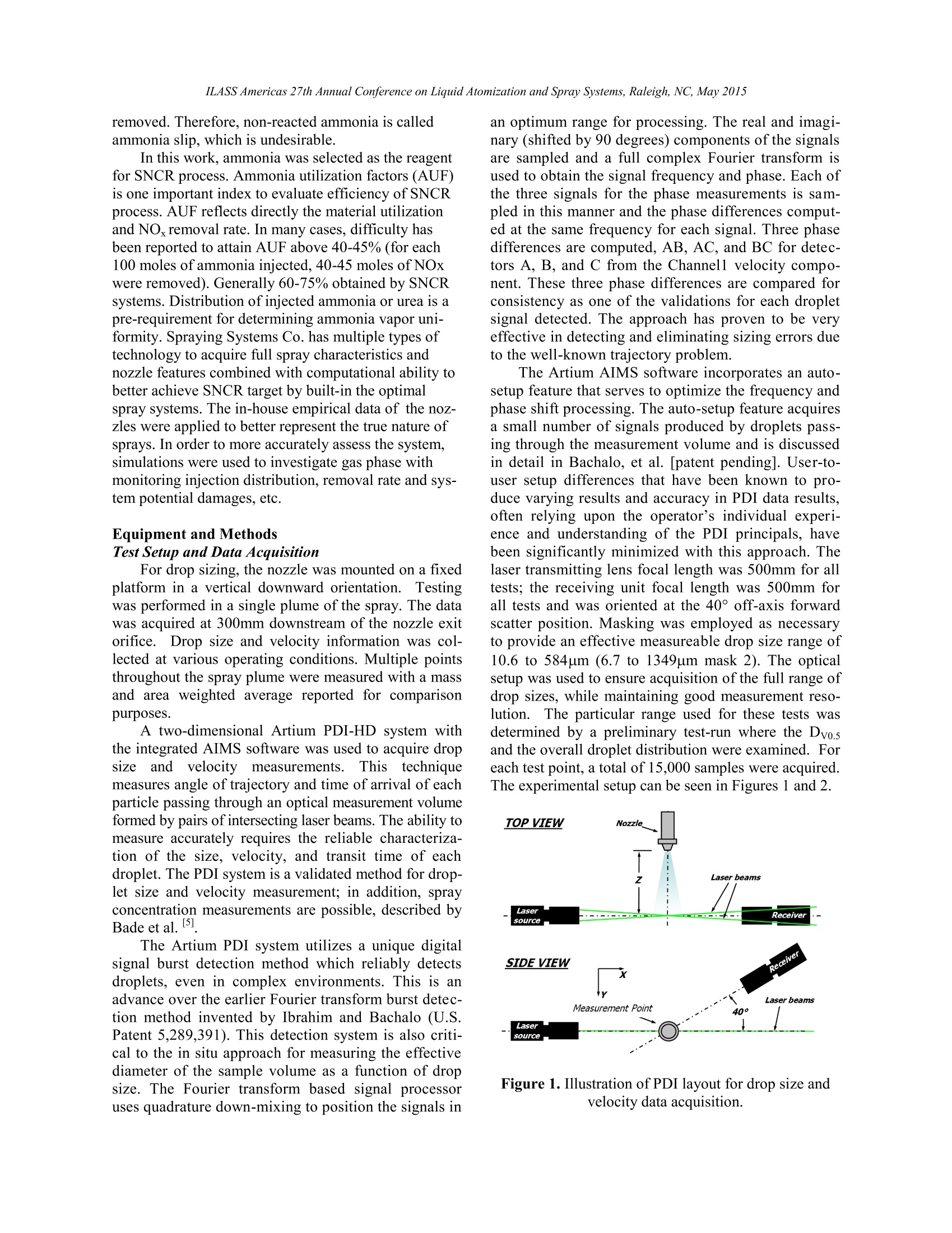
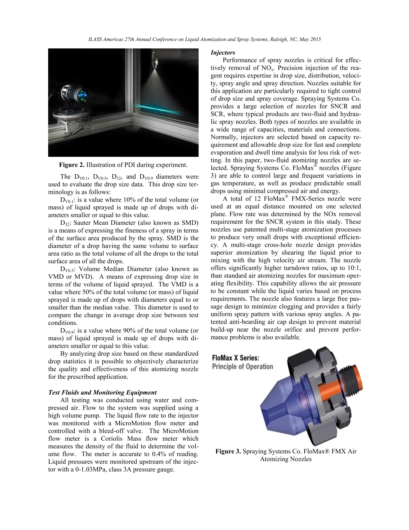
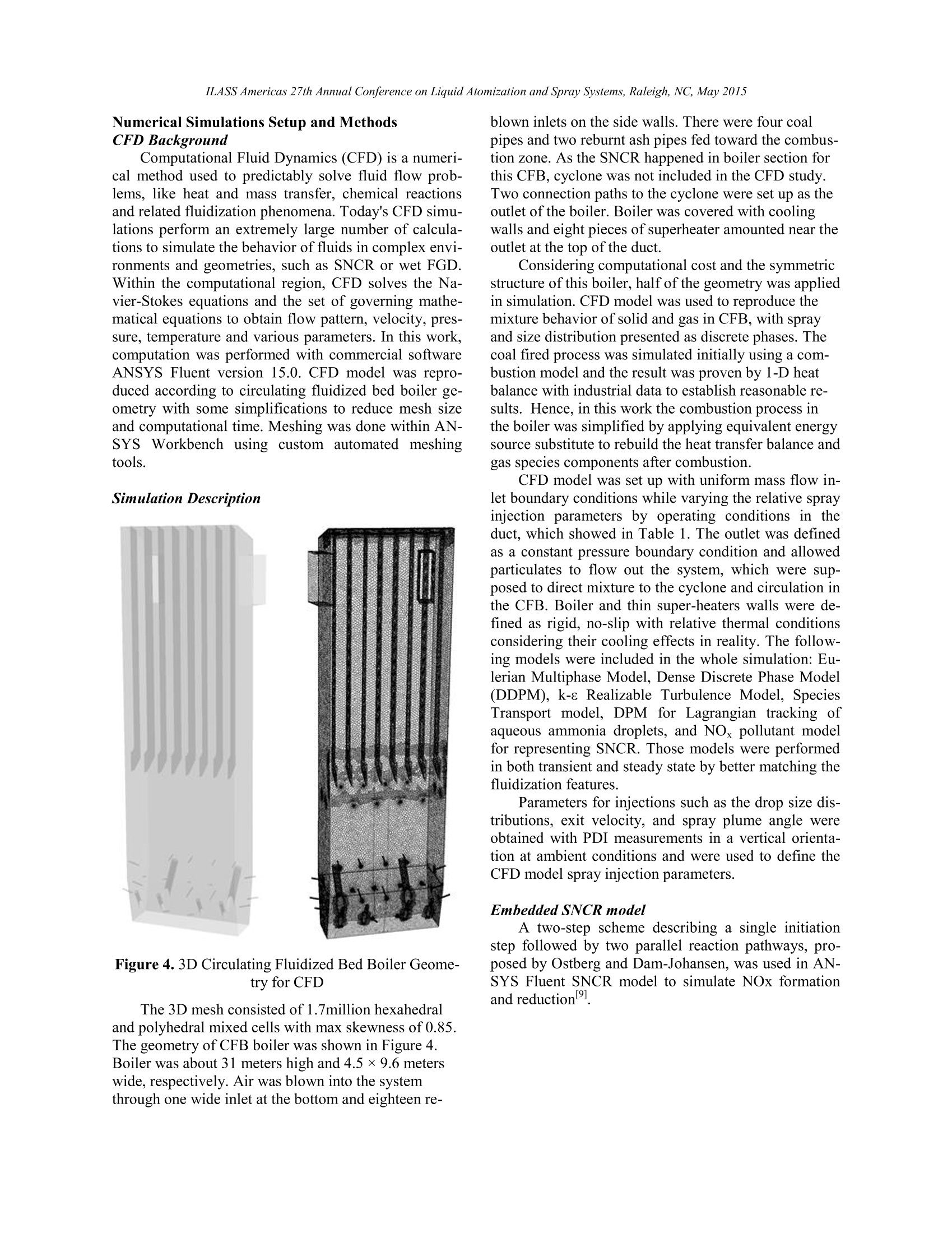
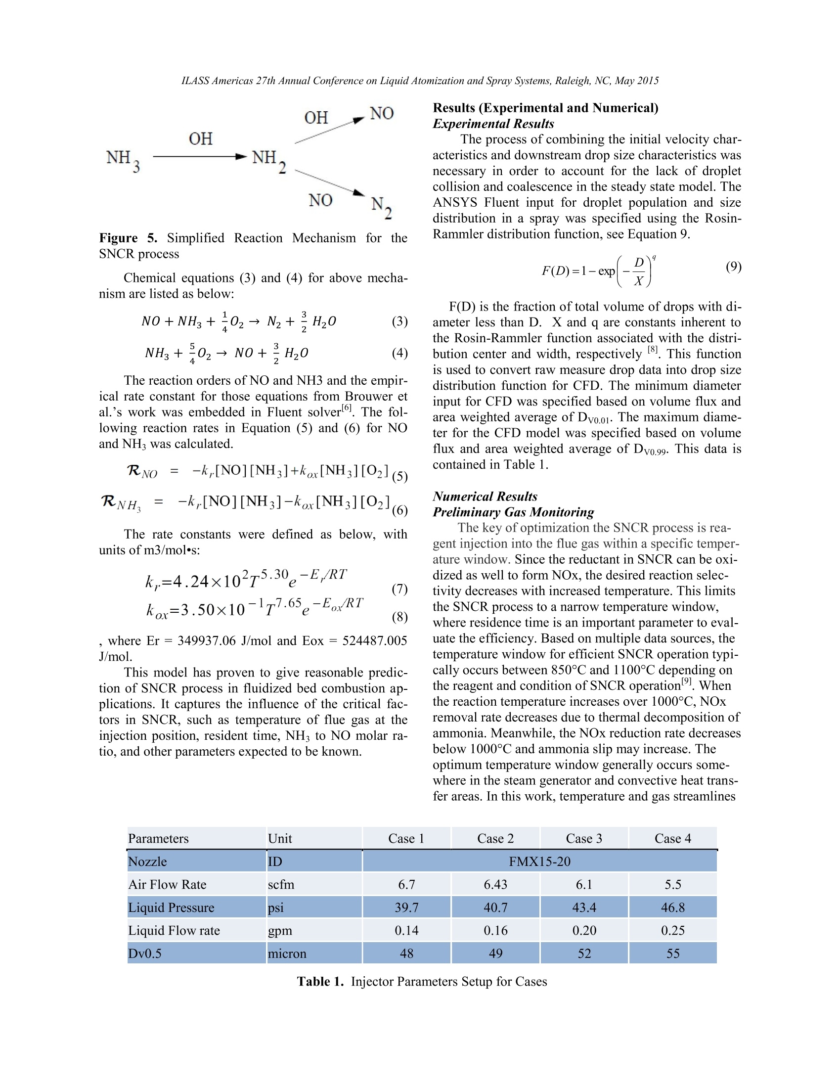
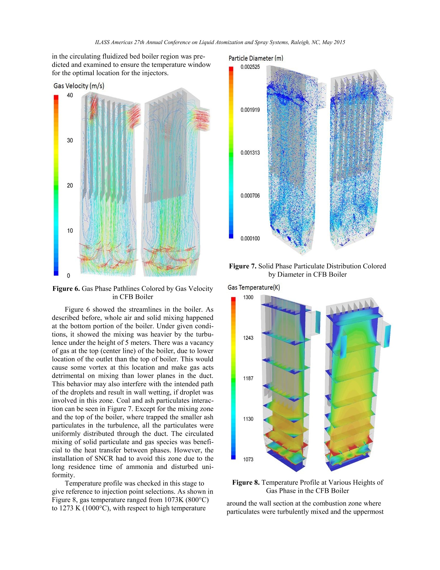
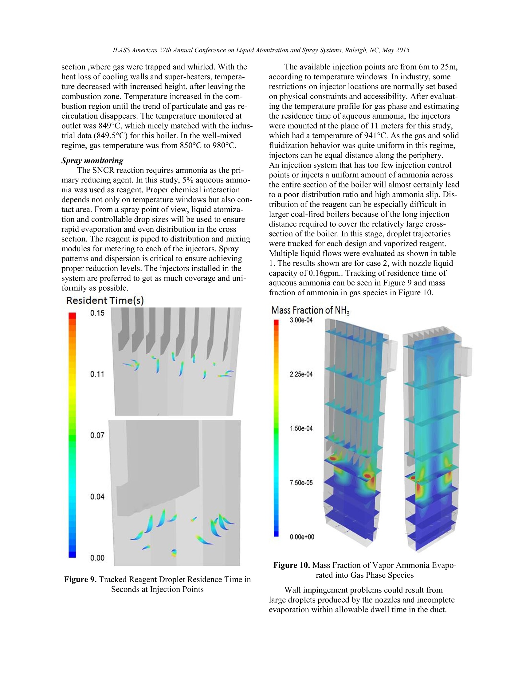
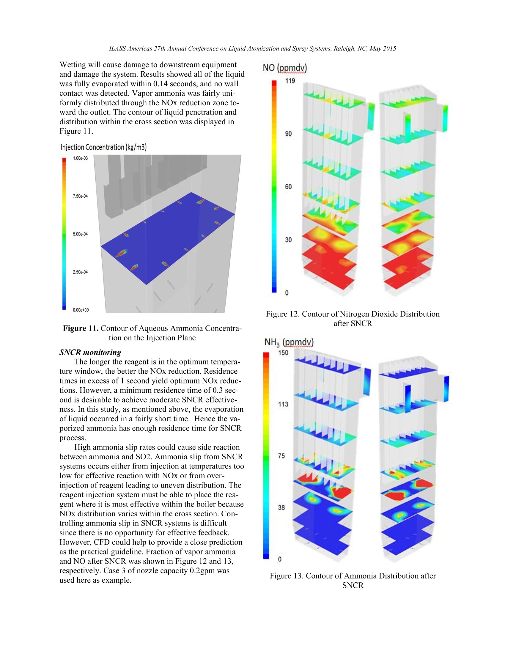
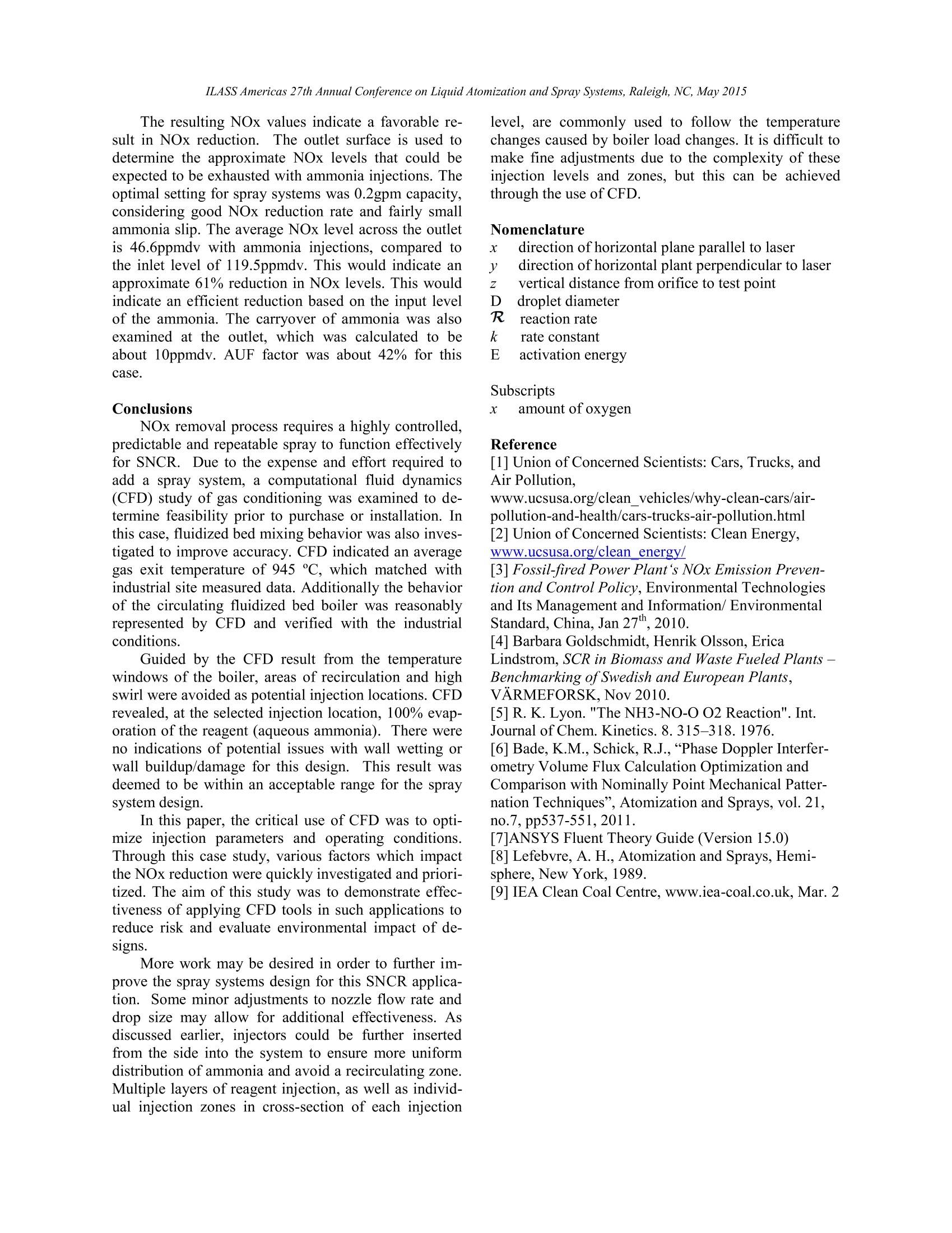
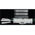
ILASS Americas 27th Annual Conference on Liquid Atomization and Spray Systems, Raleigh, NC, May 2015 SNCR Efficiency Study of Optimization of Spray Systems in CFB Fang Li*, Kathleen J. Brown, and Rudi J. Schick Spray Analysis and Research Services, Spraying Systems Co. Wheaton. IL 60187-7901 USA Juan Shen Spraying Systems (China) Co., Ltd. Songjiang Industry Zone, Shanghai, 201612 China Abstract High-level Nitrogen oxides (NOx) released to the atmosphere cause health and environmental hazards. Conventionalpower plants are required to have NOx emission control systems to abide by local environmental regulations. Com-mon post-combustion techniques include selective non-catalytic reduction (SNCR) or selective catalytic reduction(SCR) techniques. SNCR is a proven technology that can be implemented virtually without affecting existing indus-trial operations with low capital cost. SNCR is a method involving either aqueous ammonia or urea as the reagentinjected into flue gas in the boiler/furnace within specific temperature range. This method commonly reduces theemission of NO, by 30-50%. However, high reductions can be achieved by system optimization. Placement withinthe proper temperature window, distribution within the cross section and residence time of reagent significantly in-fluence performance of an SNCR system. Therefore, spray lance and nozzle design is crucial for assurance of oper-ating efficiency and ammonia utilization. In this paper, an SNCR system in a circulating fluidized bed (CFB) boiler was studied with using ComputationalFluid Dynamics (CFD) simulations, as it relates to spray technology. The simulation solves Navier-Stokes equa-tions with heat and mass transfer using ANSYS Fluent SNCR model with Lagrangian multiphase models and spe-cies transport model. CFD was used to diagnose the gas phase behavior and thermal distribution, to determine opti-mal spray placement and maximum penetration. The focus of this work was the parameters of the injection, whichwere determined based on test data acquired through in-house laboratory equipment. Temperature profile, pollutantreduction, ammonia slippage and wall impingement were used from the CFD results to assist determining the bestspray design to achieve the greatest efficiency. ( *Corresponding author: Fang.Li@spray.com ) Introduction NOx is the term of nitrogen oxides, in atmosphericchemistry referring to total concentration of nitric oxide(NO) and nitrogen dioxide (NO2), which is producedmainly from the endothermic reaction of nitrogen andoxygen in the high temperature combustion process.With industrial development and heavy traffic, air pol-lution of nitrogen oxides emitted into atmosphere canbe significant. In 2013, vehicles produce more than30% of carbon monoxide and nitrogen oxides in ourenvironment with over 25% of global warming pollu-tion. Meanwhile, power generation is the largestsource of air pollutants and global warming emissionsin U.S.2. High-level NOx causes health and environ-mental hazards by deteriorating water quality, formingsmog and acid rains even tropospheric ozone. OnMarch 2014, the U.S. Environmental Protection Agen-cy (EPA) announced new, tighter fuel standards as partof ongoing initiatives to lower greenhouse gas emis-sions. Waste, cement, glass, power and steel plantsalong with OEMs around the world are required to haveDeNOx solutions in their process. Although coal contributes nearly 80% of all powerplant carbon emissions, it produces about half our elec-tricity. Conventional power plants, which burn coal,waste and biomass, are required to have nitrogen oxideemission control systems met local environmental regu-lations. With the need of production and more stringentNOx emission requirement, primary NOx abatement(low NOx combustion technology) was no longer suffi-cient. Therefore, secondary abatement techniques aregetting increasing consideration, normally known asselective non-catalytic reduction (SNCR) or selectivecatalytic reduction (SCR). In China, SCR is preferred inthe new, renovated or expanded units and anthraciteburning units; while SNCR is often selected in unitsburning bituminous coal and lignite. In Japan, SNCRtechnologies came into commercial use on oil-or gas-fired power plants in the middle of the 1970s. In Eu-rope, new biomass fired plants and co-combustionplants prefer SNCR. On the other hand, waste firedplants choose SCR4. In the USA, SNCR systems havebeen used commercially on coal-fired power plantssince the early 1990s. The attractions of SNCR systems are their lowercapital equipment cost and extremely versatile naturefor medium levels of NOx control. Also SNCR is quitecompatible with other upstream and downstream NOxremoval technologies, which might have been perma-nently placed in the process. Nowadays, SNCR is ap-plied in many industries including: power, steel, pulpand paper, petrochemical, waste to energy, glass andothers. In this paper, a SNCR system in Circulating Fluid-ized Bed (CFB) boiler was studied and diagnosed byusing Computational Fluid Dynamics (CFD). It solves Navier-Stokes equations with heat and mass transferusing ANSYS FLUENT SNCR model, Lagrangian-Eulerian multiphase model and species transport modelto examine the measured data from industrial units.CFD was used to diagnose the gas behavior, bypasses,spray coverage, temperature field, pollutant reduction,ammonia slippage, and wall impingement to assist de-termining the best spray design for achieving the great-est efficiency. All parameters for the injections werefrom nozzle characterization tests at Spraying SystemsCO. Technical ApproachSNCR SNCR is a proven technology that can be imple-mented virtually without affecting existing industrialoperations and considerable low capital cost. It is oftenselected for cement industry, as it is suitable for bothnew and existing dry kiln systems in operation or to beon market. This is a method involving either aqueousammonia or urea as the reagent injected into flue gas inthe boiler/furnace within temperature window range of1400-2000°F. Urea is a safe material and is easy tohandle and store; while use of aqueous ammonia rea-gent is a popular way of dealing with exhaust for avoid-ing harmful of side products and ammonia slip. SNCRmethod commonly reduces the emission of NOx by 30-50%, where NOx react with reagent to form nitrogenand water. No consideration is needed for the cost andplacement of catalyst, with the high stoichiometric rati-Os. SNCR process requires three or four times as muchreagent as SCR to achieve similar reduction. Therefore,efficiency improvement can be achieved by systemoptimization, especially spray control. The proper tem-perature window, distribution within the cross sectionand residence time of reagent significantly influenceperformance of a SNCR system. Therefore, spray lanceand nozzle design for getting uniform spray distributioninto the process gas is crucial for assurance of operatingefficiency and ammonia utilization. The selective non catalytic reduction of NOx is atechnique to reduce the emission of nitrogen oxidesfrom combustion by injection of a reductant like am-monia (NH) or urea (CO(NH2)2), which was first de-scribed by Lyon. The process involves injecting thereductant into the boiler at a specific temperature win-dow location, where it reacts according to Equation (1)and (2): The mechanism involves NH2 radicals attach toNO and decompose. Ammonia can react with othercombustion species to form side products, it also de-composes at high temperature to create NO instead of removed. Therefore, non-reacted ammonia is calledammonia slip, which is undesirable. In this work, ammonia was selected as the reagentfor SNCR process. Ammonia utilization factors (AUF)is one important index to evaluate efficiency of SNCRprocess. AUF reflects directly the material utilizationand NOx removal rate. In many cases, difficulty hasbeen reported to attain AUF above 40-45% (for each100 moles of ammonia injected, 40-45 moles of NOxwere removed). Generally 60-75%obtained by SNCRsystems. Distribution of injected ammonia or urea is apre-requirement for determining ammonia vapor uni-formity. Spraying Systems Co. has multiple types oftechnology to acquire full spray characteristics andnozzle features combined with computational ability tobetter achieve SNCR target by built-in the optimalspray systems. The in-house empirical data of the noz-zles were applied to better represent the true nature ofsprays. In order to more accurately assess the system,simulations were used to investigate gas phase withmonitoring injection distribution, removal rate and sys-tem potential damages,etc. Equipment and MethodsTest Setup and Data Acquisition For drop sizing, the nozzle was mounted on a fixedplatform in a vertical downward orientation. Testingwas performed in a single plume of the spray. The datawas acquired at 300mm downstream of the nozzle exitorifice. Drop size and velocity information was col-lected at various operating conditions. Multiple pointsthroughout the spray plume were measured with a massand area weighted average reported for comparisonpurposes. A two-dimensional Artium PDI-HD system withthe integrated AIMS software was used to acquire dropsizeeandvelocitymeasurements.Thistechniquemeasures angle of trajectory and time of arrival of eachparticle passing through an optical measurement volumeformed by pairs of intersecting laser beams. The ability tomeasure accurately requires the reliable characteriza-tion of the size, velocity, and transit time of eachdroplet. The PDI system is a validated method for drop-let size and velocity measurement; in addition, sprayconcentration measurements are possible,described byBade et al. 15] The Artium PDI system utilizes a unique digitalsignal burst detection method which reliably detectsdroplets, even in complex environments. This is anadvance over the earlier Fourier transform burst detec-tion method invented by Ibrahim and Bachalo (U.S.Patent 5,289,391). This detection system is also criti-cal to the in situ approach for measuring the effectivediameter of the sample volume as a function of dropsize. The Fourier transform based signal processoruses quadrature down-mixing to position the signals in an optimum range for processing. The real and imagi-nary (shifted by 90 degrees) components of the signalsare sampled and a full complex Fourier transform isused to obtain the signal frequency and phase. Each ofthe three signals for the phase measurements is sam-pled in this manner and the phase differences comput-ed at the same frequency for each signal. Three phasedifferences are computed, AB, AC, and BC for detec-tors A, B, and C from the Channell velocity compo-nent. These three phase differences are compared forconsistency as one of the validations for each dropletsignal detected. The approach has proven to be veryeffective in detecting and eliminating sizing errors dueto the well-known trajectory problem. The Artium AIMS software incorporates an auto-setup feature that serves to optimize the frequency andphase shift processing. The auto-setup feature acquiresa small number of signals produced by droplets pass-ing through the measurement volume and is discussedin detail in Bachalo, et al. [patent pending]. User-to-user setup differences that have been known to pro-duce varying results and accuracy in PDI data results,often relying upon the operator’s individual experi-ence and understanding of the PDI principals, havebeen significantly minimized with this approach. Thelaser transmitting lens focal length was 500mm for alltests; the receiving unit focal length was 500mm forall tests and was oriented at the 40° off-axis forwardscatter position. Masking was employed as necessaryto provide an effective measureable drop size range of10.6 to 584pm (6.7 to 1349pm mask 2). The opticalsetup was used to ensure acquisition of the full range ofdrop sizes, while maintaining good measurement reso-lution. The particular range used for these tests wasdetermined by a preliminary test-run where the Dvo.5and the overall droplet distribution were examined. Foreach test point, a total of 15,000 samples were acquired.The experimental setup can be seen in Figures 1 and 2. Figure 1. Illustration of PDI layout for drop size andvelocity data acquisition. Figure 2. Illustration of PDI during experiment. The Dvo.i, Dvo.5, D32, and Dvo.9 diameters wereused to evaluate the drop size data. This drop size ter-minology is as follows: Dvo.1: is a value where 10% of the total volume (ormass) of liquid sprayed is made up of drops with di-ameters smaller or equal to this value. D32: Sauter Mean Diameter (also known as SMD)is a means of expressing the fineness of a spray in termsof the surface area produced by the spray. SMD is thediameter of a drop having the same volume to surfacearea ratio as the total volume of all the drops to the totalsurface area of all the drops. Dvo.5: Volume Median Diameter (also known asVMD or MVD). A means of expressing drop size interms of the volume of liquid sprayed. The VMD is avalue where 50% of the total volume (or mass) of liquidsprayed is made up of drops with diameters equal to orsmaller than the median value. This diameter is used tocompare the change in average drop size between testconditions. Dvo.9: is a value where 90% of the total volume (ormass) of liquid sprayed is made up of drops with di-ameters smaller or equal to this value. By analyzing drop size based on these standardizeddrop statistics it is possible to objectively characterizethe quality and effectiveness of this atomizing nozzlefor the prescribed application. Test Fluids and Monitoring Equipment All testing was conducted using water and com-pressed air. Flow to the system was supplied using ahigh volume pump. The liquid flow rate to the injectorwas monitored with a MicroMotion flow meter andcontrolled with a bleed-off valve. The MicroMotionflow meter is a Coriolis Mass flow meter whichmeasures the density of the fluid to determine the vol-ume flowV..The meter is accurate to 0.4% of reading.Liquid pressures were monitored upstream of the injec-tor with a 0-1.03MPa, class 3A pressure gauge. Injectors Performance of spray nozzles is critical for effec-tively removal of NOx. Precision injection of the rea-gent requires expertise in drop size, distribution, veloci-ty, spray angle and spray direction. Nozzles suitable forthis application are particularly required to tight controlof drop size and spray coverage. Spraying Systems Co.provides a large selection of nozzles for SNCR andSCR, where typical products are two-fluid and hydrau-lic spray nozzles. Both types of nozzles are available ina wide range of capacities, materials and connections.Normally, injectors are selected based on capacity re-quirement and allowable drop size for fast and completeevaporation and dwell time analysis for less risk of wet-ting. In this paper, two-fluid atomizing nozzles are se-lected. Spraying Systems Co. FloMaxnozzles (Figure3) are able to control large and frequent variations ingas temperature, as well as produce predictable smalldrops using minimal compressed air and energy. A total of 12 FloMaxFMX-Series nozzle wereused at an equal distance mounted on one selectedplane. Flow rate was determined by the NOx removalrequirement for the SNCR system in this study. Thesenozzles use patented multi-stage atomization processesto produce very small drops with exceptional efficien-cy. A multi-stage cross-hole nozzle design providessuperior atomization by shearing the liquid prior tomixing with the high velocity air stream. The nozzleoffers significantly higher turndown ratios, up to 10:1,than standard air atomizing nozzles for maximum oper-ating flexibility. This capability allows the air pressureto be constant while the liquid varies based on processrequirements. The nozzle also features a large free pas-sage design to minimize clogging and provides a fairlyuniform spray pattern with various spray angles. A pa-tented anti-bearding air cap design to prevent materialbuild-up near the nozzle orifice and prevent perfor-mance problems is also available. Figure 3. Spraying Systems Co. FloMax@ FMX AirAtomizing Nozzles Numerical Simulations Setup and MethodsCFD Background Computational Fluid Dynamics (CFD) is a numeri-cal method used to predictably solve fluid flow prob-lems, like heat and mass transfer, chemical reactionsand related fluidization phenomena. Today's CFD simu-lations perform an extremely large number of calcula-tions to simulate the behavior of fluids in complex envi-ronments and geometries, such as SNCR or wet FGD.Within the computational region, CFD solves the Na-vier-Stokes equations and the set of governing mathe-matical equations to obtain flow pattern, velocity, pres-sure, temperature and various parameters. In this work,computation was performed with commercial softwareANSYS Fluent version 15.0. CFD model was repro-duced according to circulating fluidized bed boiler ge-ometry with some simplifications to reduce mesh sizeand computational time. Meshing was done within AN-SYS Workbench using custom automated meshingtools. Simulation Description Figure 4.3D Circulating Fluidized Bed Boiler Geome-try for CFD The 3D mesh consisted of 1.7million hexahedraland polyhedral mixed cells with max skewness of 0.85.The geometry of CFB boiler was shown in Figure 4.Boiler was about 31 meters high and 4.5 ×9.6 meterswide, respectively. Air was blown into the systemthrough one wide inlet at the bottom and eighteen re- blown inlets on the side walls. There were four coalpipes and two reburnt ash pipes fed toward the combus-tion zone. As the SNCR happened in boiler section forthis CFB, cyclone was not included in the CFD study.Two connection paths to the cyclone were set up as theoutlet of the boiler. Boiler was covered with coolingwalls and eight pieces of superheater amounted near theoutlet at the top of the duct. Considering computational cost and the symmetricstructure of this boiler, half of the geometry was appliedin simulation. CFD model was used to reproduce themixture behavior of solid and gas in CFB, with sprayand size distribution presented as discrete phases. Thecoal fired process was simulated initially using a com-bustion model and the result was proven by 1-D heatbalance with industrial data to establish reasonable re-sults. Hence, in this work the combustion process inthe boiler was simplified by applying equivalent energysource substitute to rebuild the heat transfer balance andgas species components after combustion. CFD model was set up with uniform mass flow in-let boundary conditions while varying the relative sprayinjection parameters by operating conditions in theduct, which showed in Table 1. The outlet was definedas a constant pressure boundary condition and allowedparticulates to flow out the system, which were sup-posed to direct mixture to the cyclone and circulation inthe CFB. Boiler and thin super-heaters walls were de-fined as rigid, no-slip with relative thermal conditionsconsidering their cooling effects in reality. The follow-ing models were included in the whole simulation: Eu-lerian Multiphase Model, Dense Discrete Phase Model(DDPM), k-: Realizable Turbulence Model, SpeciesTransport model, DPM for Lagrangian tracking ofaqueous ammonia droplets, and NOx pollutant modelfor representing SNCR. Those models were performedin both transient and steady state by better matching thefluidization features. Parameters for injections such as the drop size dis-tributions, exit velocity, and spray plume angle wereobtained with PDI measurements in a vertical orienta-tion at ambient conditions and were used to define theCFD model spray injection parameters. Embedded SNCR model A two-step scheme describing a single initiationstep followed by two parallel reaction pathways, pro-posed by Ostberg and Dam-Johansen, was used in AN-SYS Fluent SNCR model to simulate NOx formationand reduction OH -NO Figure 5. Simplified Reaction Mechanism for theSNCR process Chemical equations (3) and (4) for above mecha-nism are listed as below: The reaction orders of NO and NH3 and the empir-ical rate constant for those equations from Brouwer etal.’s work was embedded in Fluent solver. The fol-lowing reaction rates in Equation (5) and (6) for NOand NH was calculated. The rate constants were defined as below, withunits of m3/mol·s: , where Er=349937.06 J/mol and Eox = 524487.005J/mol. This model has proven to give reasonable predic-tion of SNCR process in fluidized bed combustion ap-plications. It captures the influence of the critical fac-tors in SNCR, such as temperature of flue gas at theinjection position, resident time, NH to NO molar ra-tio, and other parameters expected to be known. Results (Experimental and Numerical)Experimental Results The process of combining the initial velocity char-acteristics and downstream drop size characteristics wasnecessary in order to account for the lack of dropletcollision and coalescence in the steady state model. TheANSYS Fluent input for droplet population and sizedistribution in a spray was specified using the Rosin-Rammler distribution function, see Equation 9. F(D) is the fraction of total volume of drops with di-ameter less than D. X and q are constants inherent tothe Rosin-Rammler function associated with the distri-bution center and width, respectively [8]. This functionis used to convert raw measure drop data into drop sizedistribution function for CFD. The minimum diameterinput for CFD was specified based on volume flux andarea weighted average of Dvo.1. The maximum diame-ter for the CFD model was specified based on volumeflux and area weighted average of Dvo.99. This data iscontained in Table 1. Numerical ResultsPreliminary Gas Monitoring The key of optimization the SNCR process is rea-gent injection into the flue gas within a specific temper-ature window. Since the reductant in SNCR can be oxi-dized as well to form NOx, the desired reaction selec-tivity decreases with increased temperature. This limitsthe SNCR process to a narrow temperature window,where residence time is an important parameter to eval-uate the efficiency. Based on multiple data sources, thetemperature window for efficient SNCR operation typi-cally occurs between 850℃ and 1100°C depending onthe reagent and condition of SNCR operation. Whenthe reaction temperature increases over 1000°C, NOxremoval rate decreases due to thermal decomposition ofammonia. Meanwhile, the NOx reduction rate decreasesbelow 1000℃ and ammonia slip may increase. Theoptimum temperature window generally occurs some-where in the steam generator and convective heat trans- fer areas. In this work, temperature and gas streamlines Parameters Unit Case 1 Case 2 Case 3 Case 4 Nozzle ID FMX15-20 Air Flow Rate scfm 6.7 6.43 6.1 5.5 Liquid Pressure psi 39.7 40.7 43.4 46.8 Liquid Flow rate gpm 0.14 0.16 0.20 0.25 Dv0.5 micron 48 49 52 55 Table 1. Injector Parameters Setup for Cases in the circulating fluidized bed boiler region was pre-dicted and examined to ensure the temperature windowfor the optimal location for the injectors. Particle Diameter (m) Gas Velocity (m/s) Figure 6. Gas Phase Pathlines Colored by Gas Velocityin CFB Boiler Figure 6 showed the streamlines in the boiler. Asdescribed before, whole air and solid mixing happenedat the bottom portion of the boiler. Under given condi-tions, it showed the mixing was heavier by the turbu-lence under the height of 5 meters. There was a vacancyof gas at the top (center line) of the boiler, due to lowerlocation of the outlet than the top of boiler. This wouldcause some vortex at this location and make gas actsdetrimental on mixing than lower planes in the duct.This behavior may also interfere with the intended pathof the droplets and result in wall wetting, if droplet wasinvolved in this zone. Coal and ash particulates interac-tion can be seen in Figure 7. Except for the mixing zoneand the top of the boiler, where trapped the smaller ashparticulates in the turbulence, all the particulates wereuniformly distributed through the duct. The circulatedmixing of solid particulate and gas species was benefi-cial to the heat transfer between phases. However, theinstallation of SNCR had to avoid this zone due to thelong residence time of ammonia and disturbed uni-formity. Temperature profile was checked in this stage togive reference to injection point selections. As shown inFigure 8, gas temperature ranged from 1073K (800℃)to 1273 K (1000°℃), with respect to high temperature Figure 7. Solid Phase Particulate Distribution Coloredby Diameter in CFB Boiler Gas Temperature(K) 1300 Figure 8. Temperature Profile at Various Heights ofGas Phase in the CFB Boiler around the wall section at the combustion zone whereparticulates were turbulently mixed and the uppermost section ,where gas were trapped and whirled. With theheat loss of cooling walls and super-heaters, tempera-ture decreased with increased height, after leaving thecombustion zone. Temperature increased in the com-bustion region until the trend of particulate and gas re-circulation disappears. The temperature monitored atoutlet was 849℃, which nicely matched with the indus-trial data (849.5℃) for this boiler. In the well-mixedregime, gas temperature was from 850°℃ to 980℃. Spray monitoring The SNCR reaction requires ammonia as the pri-mary reducing agent. In this study, 5% aqueous ammo-nia was used as reagent. Proper chemical interactiondepends not only on temperature windows but also con-tact area. From a spray point of view, liquid atomiza-tion and controllable drop sizes will be used to ensurerapid evaporation and even distribution in the crosssection. The reagent is piped to distribution and mixingmodules for metering to each of the injectors. Spraypatterns and dispersion is critical to ensure achievingproper reduction levels. The injectors installed in thesystem are preferred to get as much coverage and uni-formity as possible. Resident Time(s) Figure 9. Tracked Reagent Droplet Residence Time inSeconds at Injection Points The available injection points are from 6m to 25m,according to temperature windows. In industry, somerestrictions on injector locations are normally set basedon physical constraints and accessibility. After evaluat-ing the temperature profile for gas phase and estimatingthe residence time of aqueous ammonia, the injectorswere mounted at the plane of 11 meters for this study,which had a temperature of 941°C. As the gas and solidfluidization behavior was quite uniform in this regime,injectors can be equal distance along the periphery.An injection system that has too few injection controlpoints or injects a uniform amount of ammonia acrossthe entire section of the boiler will almost certainly leadto a poor distribution ratio and high ammonia slip. Dis-tribution of the reagent can be especially difficult inlarger coal-fired boilers because of the long injectiondistance required to cover the relatively large cross-section of the boiler. In this stage, droplet trajectorieswere tracked for each design and vaporized reagent.Multiple liquid flows were evaluated as shown in table1. The results shown are for case 2, with nozzle liquidcapacity of 0.16gpm.. Tracking of residence time ofaqueous ammonia can be seen in Figure 9 and massfraction of ammonia in gas species in Figure 10. Mass Fraction of NH. Figure 10. Mass Fraction of Vapor Ammonia Evapo-rated into Gas Phase Species Wall impingement problems could result fromlarge droplets produced by the nozzles and incompleteevaporation within allowable dwell time in the duct. Wetting will cause damage to downstream equipmentand damage the system. Results showed all of the liquidwas fully evaporated within 0.14 seconds, and no wallcontact was detected. Vapor ammonia was fairly uni-formly distributed through the NOx reduction zone to-ward the outlet. The contour of liquid penetration anddistribution within the cross section was displayed inFigure 11. Injection Concentration (kg/m3) Figure 11. Contour of Aqueous Ammonia Concentra-tion on the Injection Plane SNCR monitoring The longer the reagent is in the optimum tempera-ture window, the better the NOx reduction. Residencetimes in excess of 1 second yield optimum NOx reduc-tions. However. a minimum residence time of 0.3 sec-ond is desirable to achieve moderate SNCR effective-ness. In this study, as mentioned above, the evaporationof liquid occurred in a fairly short time. Hence the va-porized ammonia has enough residence time for SNCRprocess. High ammonia slip rates could cause side reactionbetween ammonia and SO2. Ammonia slip from SNCRsystems occurs either from injection at temperatures toolow for effective reaction with NOx or from over-injection of reagent leading to uneven distribution. Thereagent injection system must be able to place the rea-gent where it is most effective within the boiler becauseNOx distribution varies within the cross section. Con-trolling ammonia slip in SNCR systems is difficultsince there is no opportunity for effective feedback.However, CFD could help to provide a close predictionas the practical guideline. Fraction of vapor ammoniaand NO after SNCR was shown in Figure 12 and 13,respectively. Case 3 of nozzle capacity 0.2gpm wasused here as example. NO (ppmdv) Figure 12. Contour of Nitrogen Dioxide Distributionafter SNCR NHs (ppmdv) 150 Figure 13. Contour of Ammonia Distribution afterSNCR The resulting NOx values indicate a favorable re-sult in NOx reduction..The outlet surface is used todetermine the approximate NOx levels that could beexpected to be exhausted with ammonia injections. Theoptimal setting for spray systems was 0.2gpm capacity,considering good NOx reduction rate and fairly smallammonia slip. The average NOx level across the outletis 46.6ppmdv with ammonia injections, compared tothe inlet level of 119.5ppmdv. This would indicate anapproximate 61% reduction in NOx levels. This wouldindicate an efficient reduction based on the input levelof the ammonia. The carryover of ammonia was alsoexamined at the outlet, which was calculated to beabout 10ppmdv. AUF factor was about 42% for thiscase. Conclusions NOx removal process requires a highly controlled,predictable and repeatable spray to function effectivelyfor SNCR. Due to the expense and effort required toadd a spray system, a computational fluid dynamics(CFD) study of gas conditioning was examined to de-termine feasibility prior to purchase or installation. Inthis case, fluidized bed mixing behavior was also inves-tigated to improve accuracy. CFD indicated an averagegas exit temperature of 945 ℃, which matched withindustrial site measured data. Additionally the behaviorof the circulating fluidized bed boiler was reasonablyrepresented by CFD and verified with the industrialconditions. Guided by the CFD result from the temperaturewindows of the boiler, areas of recirculation and highswirl were avoided as potential injection locations. CFDrevealed, at the selected injection location, 100% evap-oration of the reagent (aqueous ammonia). There wereno indications of potential issues with wall wetting orwall buildup/damage for this design. This result wasdeemed to be within an acceptable range for the spraysystem design. In this paper, the critical use of CFD was to opti-mize injection parameters and operating conditions.Through this case study, various factors which impactthe NOx reduction were quickly investigated and priori-tized. The aim of this study was to demonstrate effec-tiveness of applying CFD tools in such applications toreduce risk and evaluate environmental impact of de-signs. More work may be desired in order to further im-prove the spray systems design for this SNCR applica-tion. Some minor adjustments to nozzle flow rate anddrop size may allow for additional effectiveness. Asdiscussed earlier, injectors could be further insertedfrom the side into the system to ensure more uniformdistribution of ammonia and avoid a recirculating zone.Multiple layers of reagent injection, as well as individ-ual injection zones in cross-section of each injection level, are commonly used to follow the temperaturechanges caused by boiler load changes. It is difficult tomake fine adjustments due to the complexity of theseinjection levels and zones, but this can be achievedthrough the use of CFD. Nomenclature direction of horizontal plane parallel to laser vertical distance from orifice to test point dreaction rate y direction of horizontal plant perpendicular to laserzDDdroplet diameterkE rate constant activation energy Subscripts amount of oxygen Reference [1] Union of Concerned Scientists: Cars, Trucks, andAir Pollution. www.ucsusa.org/clean_vehicles/why-clean-cars/air-pollution-and-health/cars-trucks-air-pollution.html[2] Union of Concerned Scientists: Clean Energy,www.ucsusa.org/clean energyl ( [3] Fossil-fired Power Plant's NOx Emission Preven-tion and Control Policy, Environmental Technologiesand Its Management and Information/ Environmental Standard, China, Jan 27",2010. ) ( [4] Barbara Goldschmidt, H enrik O lsson, Erica Lindstrom, SCR in Biomass and Waste Fueled Plants - Benchmarking of Swedish and European Plants, VARMEFORSK,Nov 2010. ) ( [5] R . K. Lyon. " The NH3-NO-O O2 Reaction". Int. Journal of Chem. Kinetics. 8.315 - 318. 1 976. ) ( [6] Bade, K.M., Schick, R . J., “Phase Doppler Interfer-ometry Volume Flux Calculation Optimization and Comparison with Nominally Point Mechanical Patter-nation Techniques”, Atomization and Sprays, v ol. 21, no.7,pp537-551,2011. ) ( [ 7 ]ANSYS Fluent Theory Guide (Version 15.0) ) ( [8] Lefebvre, A. H., Atomization and Sprays, Hemi- sphere, New Y ork, 1 989. ) ( [9] IEA Clean Coal Centre, www.iea-coal.co.uk, Mar. 2 )
确定

还剩9页未读,是否继续阅读?

产品配置单

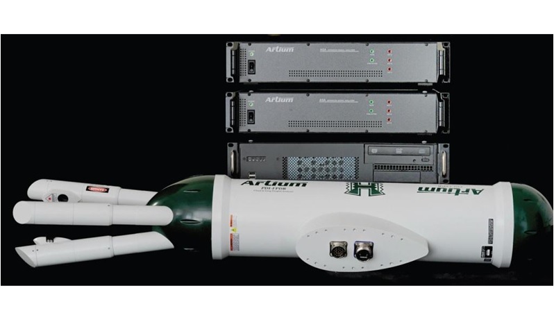
北京欧兰科技发展有限公司为您提供《循环流化床,喷雾中液滴粒径,液滴速度检测方案(气溶胶)》,该方案主要用于其他中液滴粒径,液滴速度检测,参考标准--,《循环流化床,喷雾中液滴粒径,液滴速度检测方案(气溶胶)》用到的仪器有Artium PDI-FP 双量程可机载飞行探头、激光相位多普勒干涉仪LDV,PDI,PDPA,PDA、激光诱导白炽光(LII)烟气分析仪
推荐专场


相关方案
更多
该厂商其他方案
更多