


Along with the rapid growth of research of microfluidics, monitoring and understanding micro flow
behavior is a challenge for researchers. Particle Image Velocimetry (PIV), a powerful tool that
makes flow visible, was extended to microscale by Santiago et al. 1998. In this paper, we presented
the micro Particle Image Velocimetry (μPIV) system at Nanyang Technological University (NTU),
its calibration and characterizations of microfluidic devices using μPIV. Since the fully developed
microchannel flow has been well investigated, it is suitable to calibrate the measurements of μPIV.
In our experiment, an in-channel microdispenser fabricated on printed circuit board is used to form a
microchannel. A syringe pump forces water that contains fluorescent particles. The flow field is obtained
by μPIV. At the same time, a three-dimensional model with ANSYS/FLOTRAN was used.
The comparison between the two results demonstrates that our μPIV system works well. Furthermore
we use this system to characterize a Tesla valve - a non-moving part valve. The valve consists
of a fluid channel structure that has rectification property, which favors forward flow while hampers
reverse flow. The velocity fields are also validated by ANSYS/FLOTRAN.
方案详情

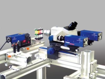
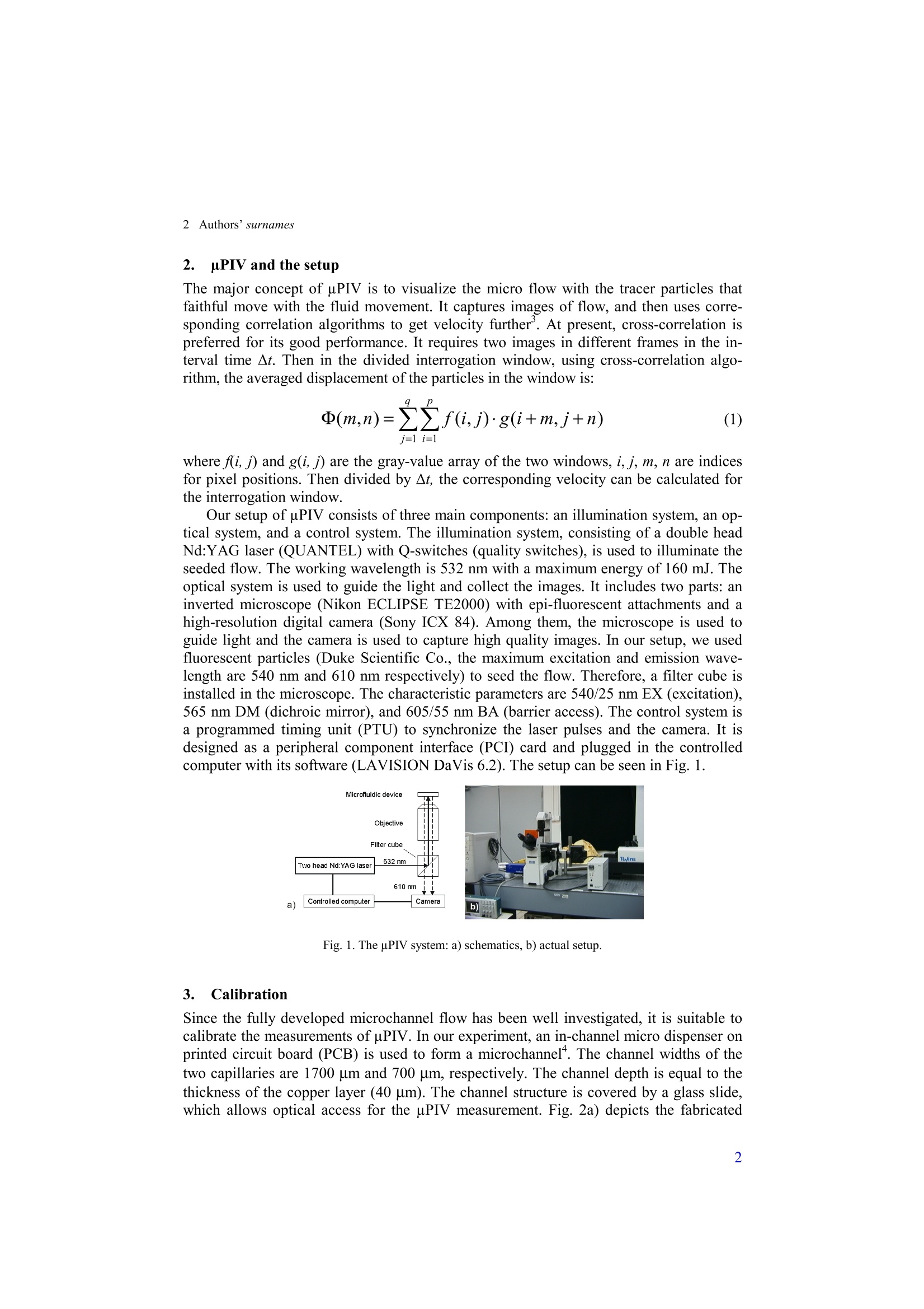
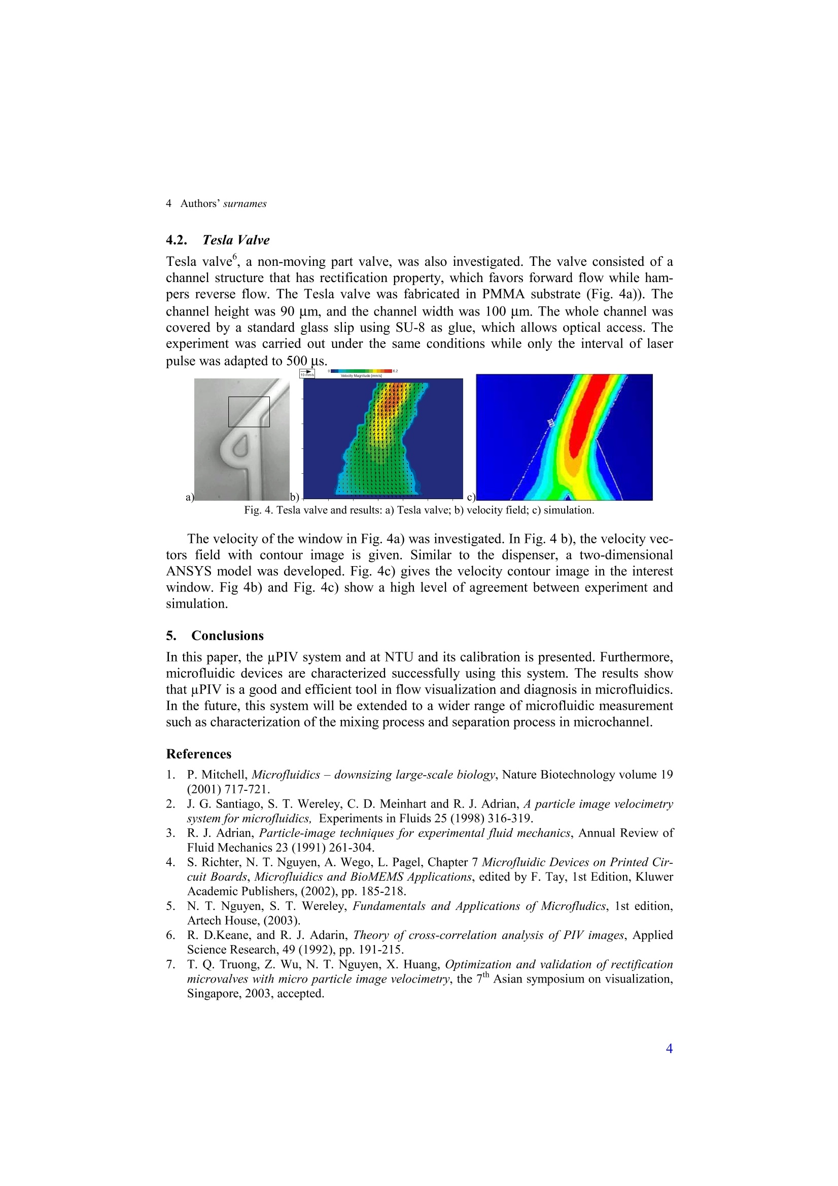
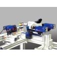
International Journal of Computational Engineering ScienceVol.0, No.0 (2002)000-000O Imperial College Press Shortened Title of paper 3 CHARACTERIZATION OF MICROFLUIDIC DEVICES USING MICROPARTICLE IMAGE VELOCIMETRY ZHIGANG WU, THAI-QUANG TRUONG, NAM-TRUNG NGUYEN, and XIAO-YANG HUANG School of Mechanical and Production EngineeringNanyang Technological University, Singapore, 639798Email: zgwu@pmail.ntu.edu.sg Received (received date)Revised (revised date) Along with the rapid growth ofresearch of microfluidics, monitoring and understanding micro flowbehavior is a challenge for researchers. Particle Image Velocimetry (PIV), a powerful tool thatmakes flow visible, was extended to microscale by Santiago et al. 1998. In this paper, we presentedthe micro Particle Image Velocimetry (uPIV) system at Nanyang Technological University (NTU),its calibration and characterizations of microfluidic devices using uPIV. Since the fully developedmicrochannel flow has been well investigated, it is suitable to calibrate the measurements of uPIV.In our experiment, an in-channel microdispenser fabricated on printed circuit board is used to form amicrochannel. A syringe pump forces water that contains fluorescent particles. The flow field is ob-tained by uPIV. At the same time, a three-dimensional model with ANSYS/FLOTRAN was used.The comparison between the two results demonstrates that our uPIV system works well. Further-more we use this system to characterize a Tesla valve -a non-moving part valve. The valve consistsof a fluid channel structure that has rectification property, which favors forward flow while hampersreverse flow. The velocity fields are also validated by ANSYS/FLOTRAN. Keywords:Microfluidic; Characterization; uPIV; Microchannel; Tesla Valve. 1.. Introduction With the development of science and technology, microfluidics grows very quickly re-cently. Many microfluidic devices such as flow sensors, chemical reactors, separationcapillaries, pumps, and valves were developed and investigated,. They are applied in thewide fields of chemical analysis, drug delivery, biological sensing and analysis. It has ahigh potential value and high capacity of commercial market in the coming future. There-fore, monitoring and understanding the flow in micro scale is urgent at present. However, due to micorscale effects, monitoring micro flow become one of the keychallenges in microfluidics . Particle Image Velocimetry (PIV) based on optical meas-urement, a powerful tool that make flow visible, was extended to micorscale by Santiagoet al.. The most significant benefit is that it cannot affect the flow field. Furthermore, itcan get the information in the whole field. In this paper, we presented the pPIV system atNTU, its calibration and characterization of microfluidic devices using uPIV. 2 Authors’surnames 2.pPIV and the setup The major concept of uPIV is to visualize the micro flow with the tracer particles thatfaithful move with the fluid movement. It captures images of flow, and then uses corre-sponding correlation algorithms to get velocity further’. At present, cross-correlation ispreferred for its good performance. It requires two images in different frames in the in-terval time At. Then in the divided interrogation window, using cross-correlation algo-rithm, the averaged displacement of the particles in the window is: where f(i, j) and g(i,j) are the gray-value array of the two windows, i, j, m, n are indicesfor pixel positions. Then divided by At, the corresponding velocity can be calculated forthe interrogation window. Our setup ofuPIV consists of three main components: an illumination system, an op-tical system, and a control system. The illumination system, consisting of a double headNd:YAG laser (QUANTEL) with Q-switches (quality switches), is used to illuminate theseeded flow. The working wavelength is 532 nm with a maximum energy of 160 mJ. Theoptical system is used to guide the light and collect the images. It includes two parts: aninverted microscope (Nikon ECLIPSE TE2000) with epi-fluorescent attachments and ahigh-resolution digital camera (Sony ICX 84). Among them, the microscope is used toguide light and the camera is used to capture high quality images. In our setup, we usedfluorescent particles (Duke Scientific Co., the maximum excitation and emission wave-length are 540 nm and 610 nm respectively) to seed the flow. Therefore, a filter cube isinstalled in the microscope. The characteristic parameters are 540/25 nm EX (excitation),565 nm DM (dichroic mirror), and 605/55 nm BA (barrier access). The control system isa programmed timing unit (PTU) to synchronize the laser pulses and the camera. It isdesigned as a peripheral component interface (PCI) card and plugged in the controlledcomputer with its software (LAVISION DaVis 6.2). The setup can be seen in Fig. 1. Fig. 1. The uPIV system: a) schematics, b) actual setup. 3.. Calibration Since the fully developed microchannel flow has been well investigated, it is suitable tocalibrate the measurements ofuPIV. In our experiment, an in-channel micro dispenser onprinted circuit board (PCB) is used to form a microchannel. The channel widths of thetwo capillaries are 1700 um and 700 um, respectively. The channel depth is equal to thethickness of the copper layer (40 um). The channel structure is covered by a glass slide,which allows optical access for the uPIV measurement. Fig. 2a) depicts the fabricated channel structures with the image windows. Among the widows, the bottom window isused to calibrate the system; the top window is used to characterize the flow in the dis-penser (see section4). Fig. 2. Calibration: a) channel structure;b) velocity vectors plot; c) comparison of flow velocity. In our experiment, the water was driven by a syringe pump and 1 um red fluorescentparticle was used to seed the flow.With a 20x objectives, the images were captured bycamera. The corresponding image size is 240 um ×320 um. Thus, the whole channelwidth (700 um) could not be observed. The two 24 mJ lasers were short in the interval of450 us to excite the particles. The evaluation was carried out by PIVview (PivTecGmbH, Germany) and then EDPIV from Purdue University. A 32 pixelsx32 pixels withan overlap ratio of 50% interrogation window, which satisfies the Nyquist sampling crite-rion, is used in the evaluation. The result can be seen in the Fig. 2b). Then using ANSYS/FLOTRAN, a three-dimensional numerical model was set up tovalidate the measurement results. The velocity profile of section was extracted and com-pared with the measurement results. In Fig. 2c), the line denotes numerical solution andcircles denote the measurement results. They agree well with each other. This comparisonindicates our system works well can be used to characterize other microfluidic devicesfurther. 4.Experimental Results and Discussions After the calibration, we investigated another flow fields: the transition area in the dis-penser and a Tesla valve fabricated in polymethyl methacrylate (PMMA). 4.1.。Transition Area This experiment follows the above calibration under same conditions. That is the topwindow in Fig. 2a). The channel width changes from 1700 um to 700 um here. Using thesame methods, the results are put in Fig. 3a) the particle image and Fig.3b) the velocityfield with contour image. In the velocity field, it is easy to see the change of velocityfrom high to low. Recurring to the ANSYS model set up in section 3, the contour velocityimage is given in Fig. 3c). The two results agree well, too. Fig. 3. Results of the transition area: a) particle image; b) velocity field; c) simulation. 4 Authors’surnames 4.2. Tesla Valve Tesla valve, a non-moving part valve, was also investigated. The valve consisted of achannel structure that has rectification property, which favors forward flow while ham-pers reverse flow. The Tesla valve was fabricated in PMMA substrate (Fig. 4a)). Thechannel height was 90 um, and the channel width was 100 um. The whole channel wascovered by a standard glass slip using SU-8 as glue, which allows optical access. Theexperiment was carried out under the same conditions while only the interval of laserpulse was adapted to 500 us. Fig. 4. Tesla valve and results: a) Tesla valve; b) velocity field; c) simulation. The velocity of the window in Fig. 4a) was investigated. In Fig. 4 b), the velocity vec-tors field with contour image is given. Similar to the dispenser, a two-dimensionalANSYS model was developed. Fig. 4c) gives the velocity contour image in the interestwindow. Fig 4b) and Fig. 4c) show a high level of agreement between experiment andsimulation. 5.Conclusions In this paper, the uPIV system and at NTU and its calibration is presented. Furthermore,microfluidic devices are characterized successfully using this system. The results showthat uPIV is a good and efficient tool in flow visualization and diagnosis in microfluidics.In the future, this system will be extended to a wider range of microfluidic measurementsuch as characterization of the mixing process and separation process in microchannel. References 1.P. Mitchell, Microfluidics - downsizing large-scale biology, Nature Biotechnology volume 19(2001) 717-721. 2. J. G. Santiago, S. T. Wereley, C. D. Meinhart and R. J. Adrian, A particle image velocimetrysystem for microfluidics, Experiments in Fluids 25 (1998) 316-319. 3. R. J. Adrian, Particle-image techniques for experimental fluid mechanics, Annual Review ofFluid Mechanics 23 (1991)261-304. 4. S. Richter, N. T. Nguyen, A. Wego, L. Pagel, Chapter 7 Microfluidic Devices on Printed Cir-cuit Boards, Microfluidics and BioMEMS Applications, edited by F. Tay, 1st Edition, KluwerAcademic Publishers, (2002), pp. 185-218. 5. N. T. Nguyen, S. T. Wereley, Fundamentals and Applications of Microfludics, 1st edition,Artech House, (2003). 6. R. D.Keane, and R. J. Adarin, Theory ofcross-correlation analysis of PIV images, AppliedScience Research, 49 (1992), pp. 191-215. 7.T. Q. Truong,Z. Wu, N. T. Nguyen, X. Huang, Optimization and validation ofrectificationmicrovalves with micro particle image velocimetry, the 7th Asian symposium on visualization,Singapore, 2003, accepted.
确定

还剩2页未读,是否继续阅读?

产品配置单

北京欧兰科技发展有限公司为您提供《微流动装置中速度场,速度矢量场检测方案(粒子图像测速)》,该方案主要用于其他中速度场,速度矢量场检测,参考标准--,《微流动装置中速度场,速度矢量场检测方案(粒子图像测速)》用到的仪器有显微粒子成像测速系统(Micro PIV)、PLIF平面激光诱导荧光火焰燃烧检测系统
推荐专场


相关方案
更多
该厂商其他方案
更多