


方案详情
文
Pulsed jets have found a wide variety of applications in the area of flow control during
the recent years. The goal of the current study is to identify the flow field and mixing
characteristics associated with an incompressible circular jet through a flexible nozzle. The
flow was self-excited over a range of conditions and produced a pulsatile flow. The frequency
of excitation was found to be between 150-175Hz. Phase-locked and time averaged 2D
Particle image Velocimetry (PIV) was used to study the dynamic characteristics of the flow.
The flow field shows that two different modes could be excited depending on nozzle
characteristic. The flapping mode was associated with alternate shedding of vortices. This
introduces strong steering of the jet to one side or the other. Turbulence, Jet spread and
entrainment characteristics were far more superior to the non-flapping or a pulsed jet. The
second mode which was a non-flapping mode is associated with the formation of a counter
rotating vortex pair. The turbulence associated with both these modes was convected along
with the vortical structure in the flow. The jet vortices formed by the self-excited flow were
not just convected by the flow, but these determined the flow field and mixing characteristics
of the jet.
方案详情

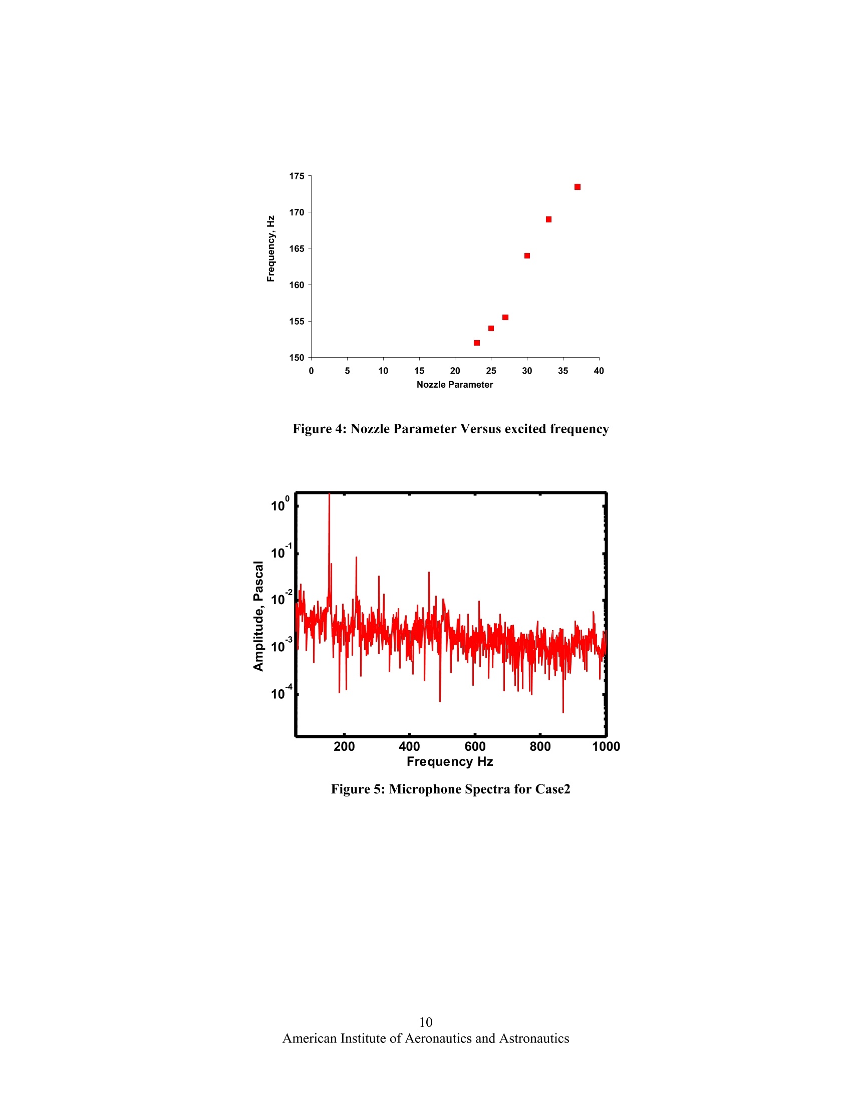
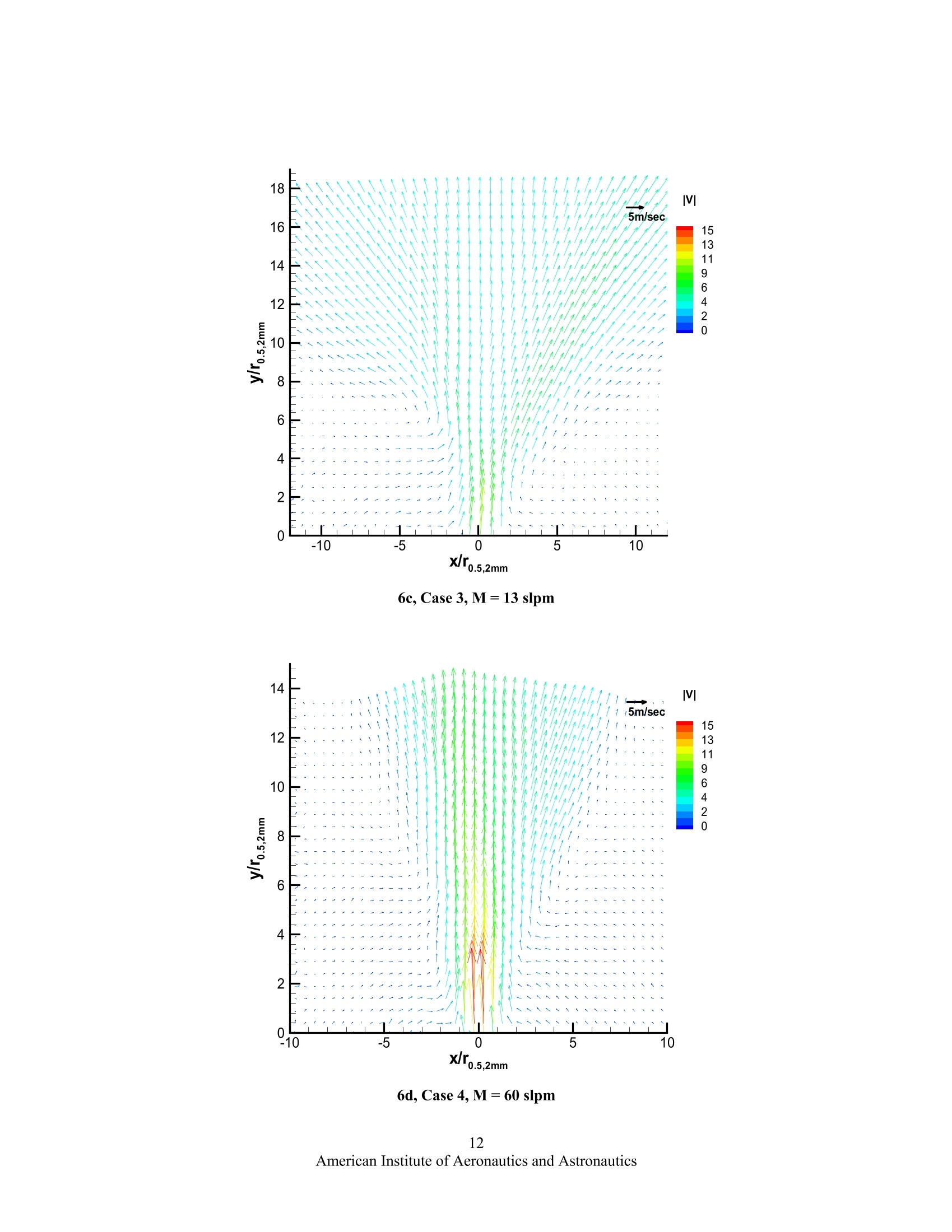
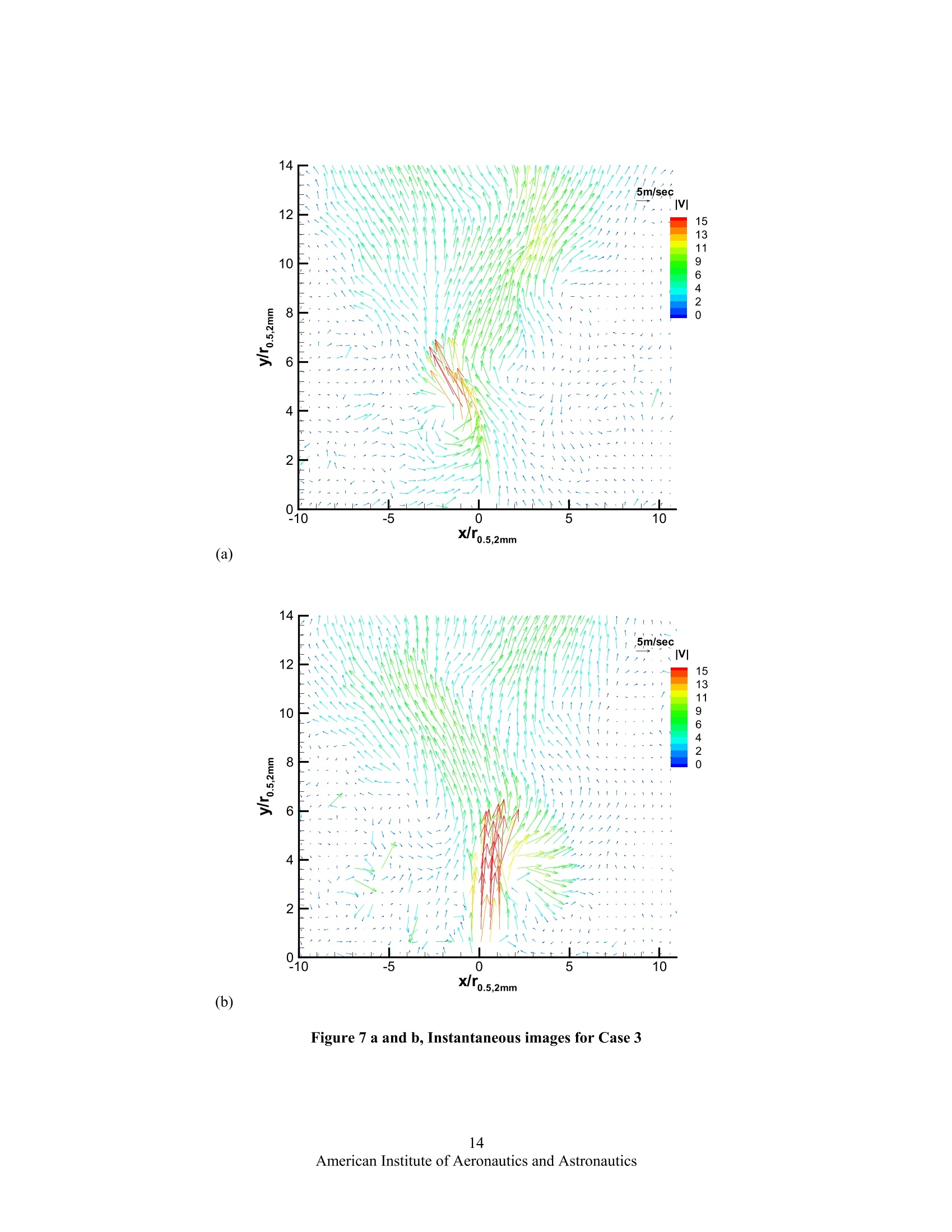
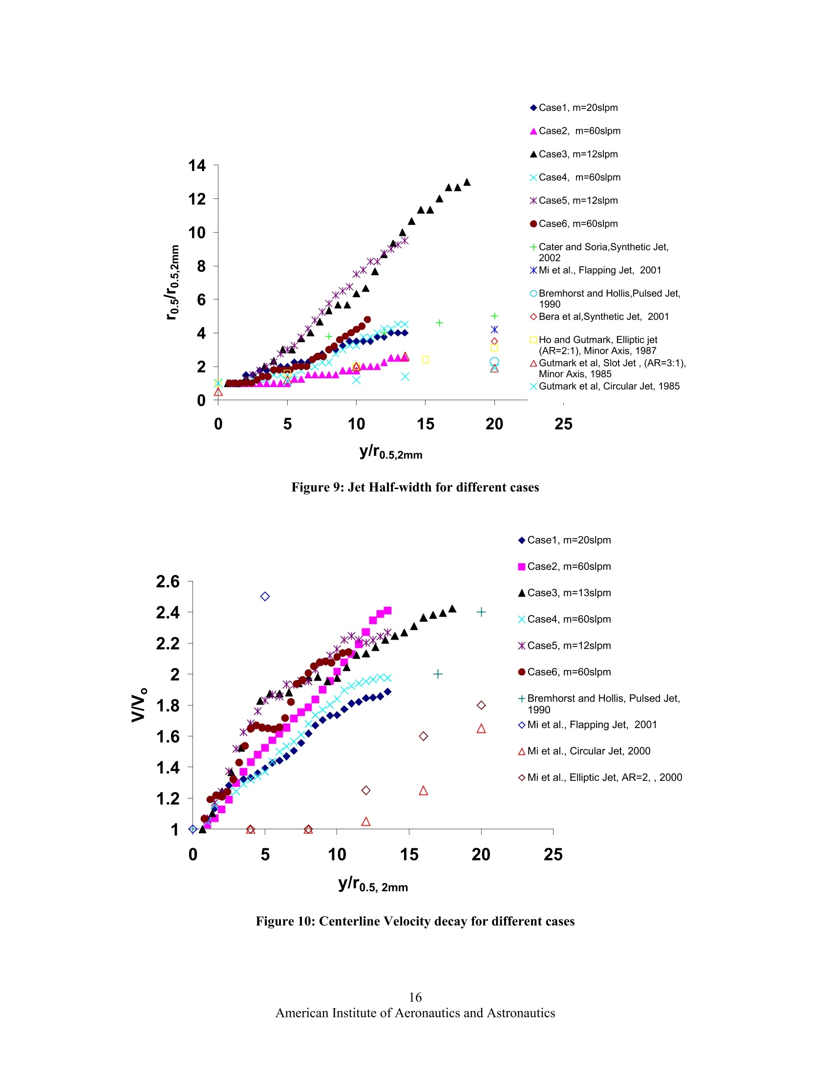
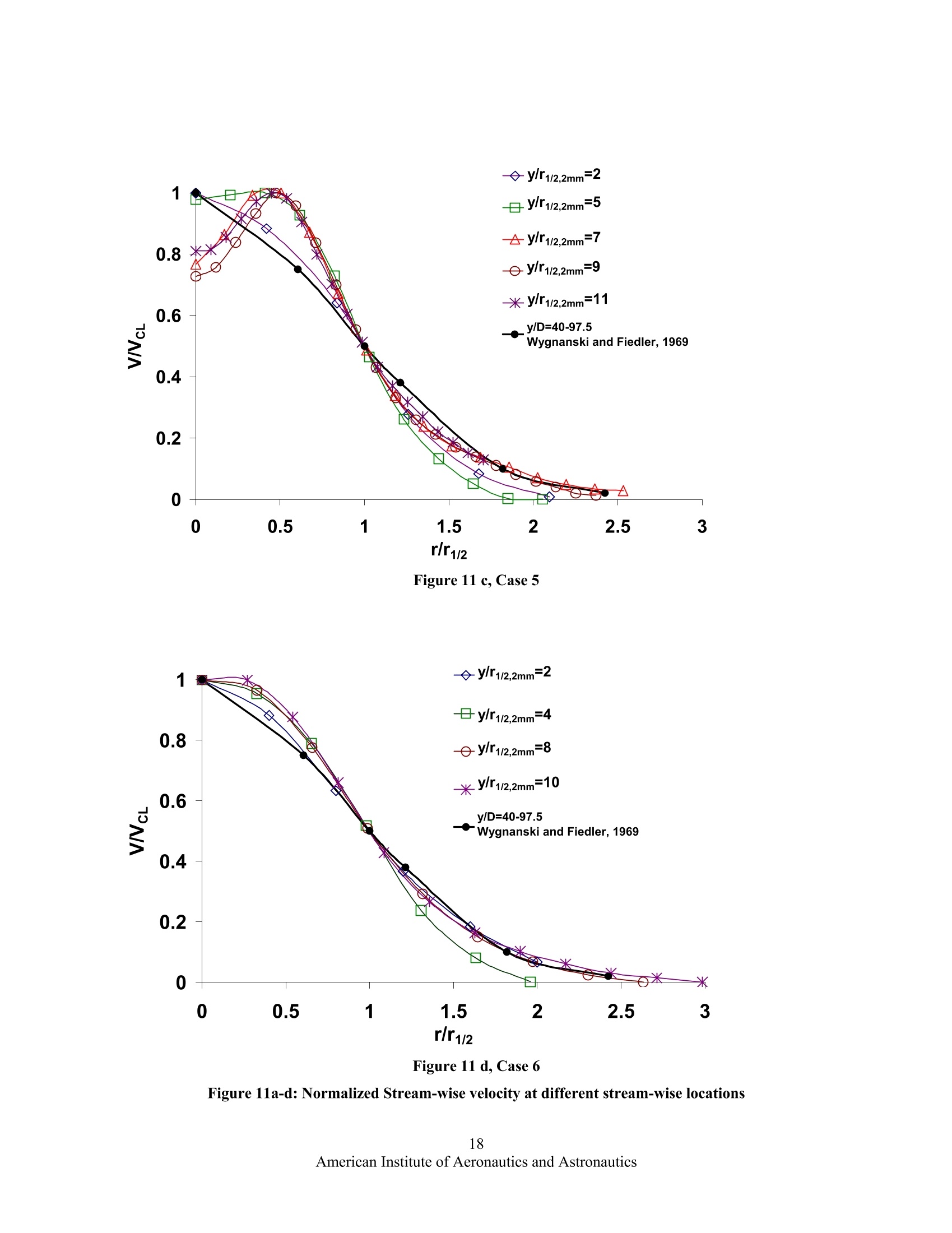
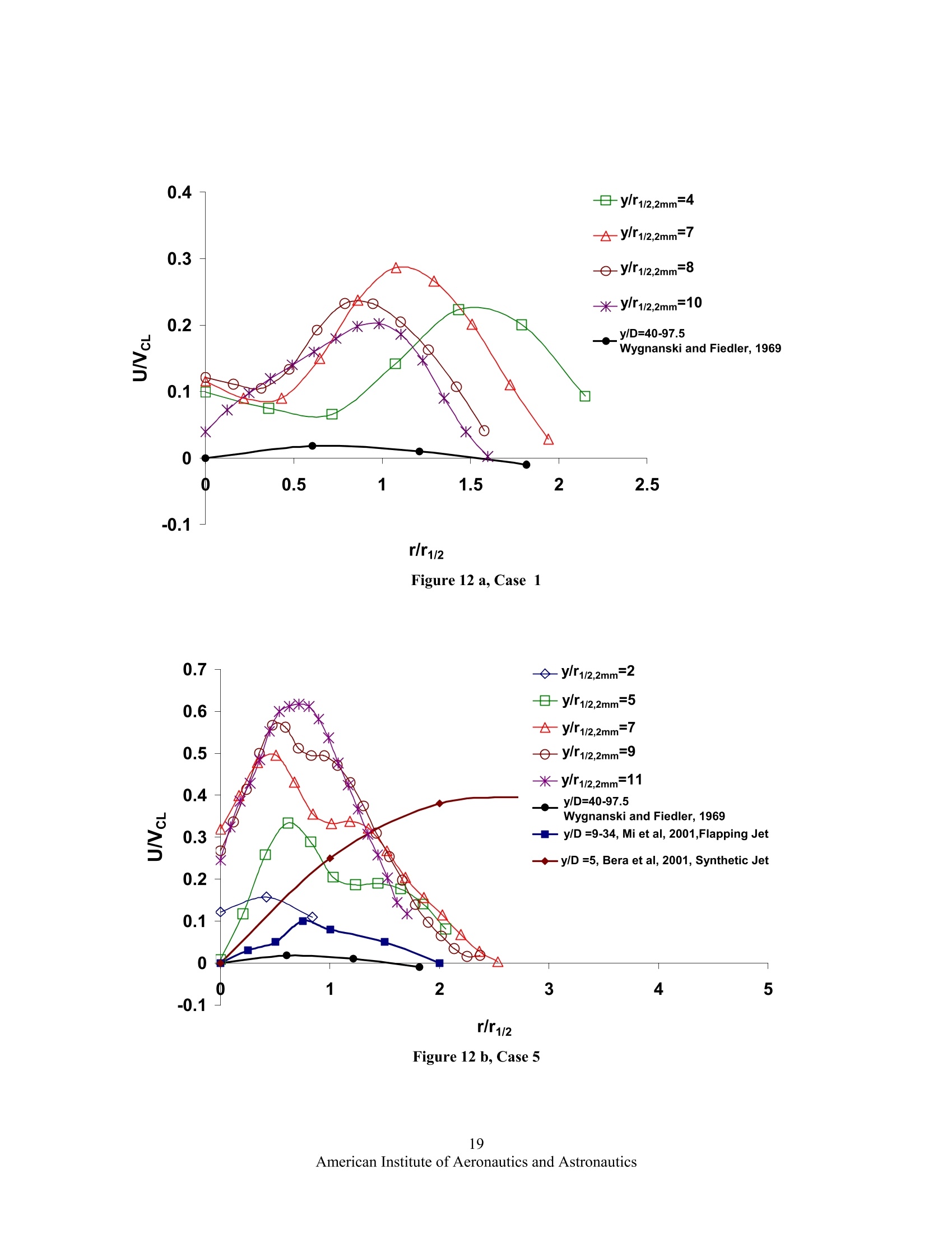
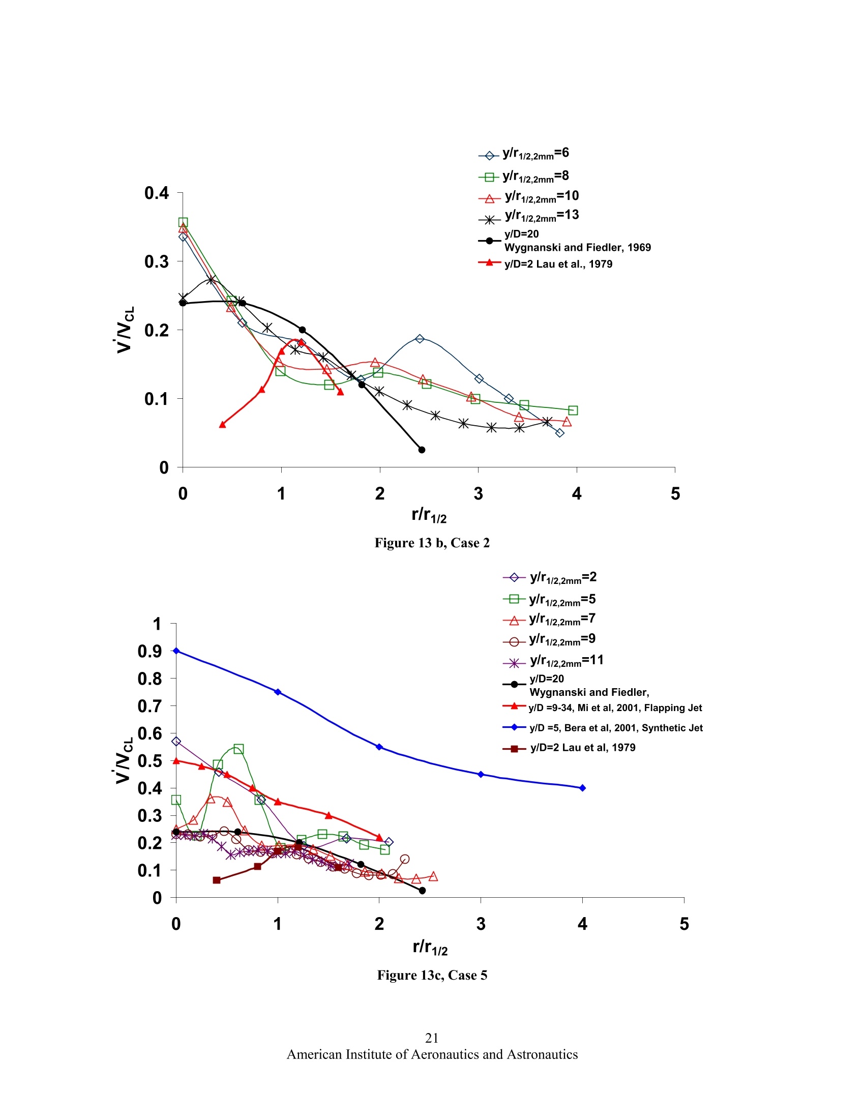
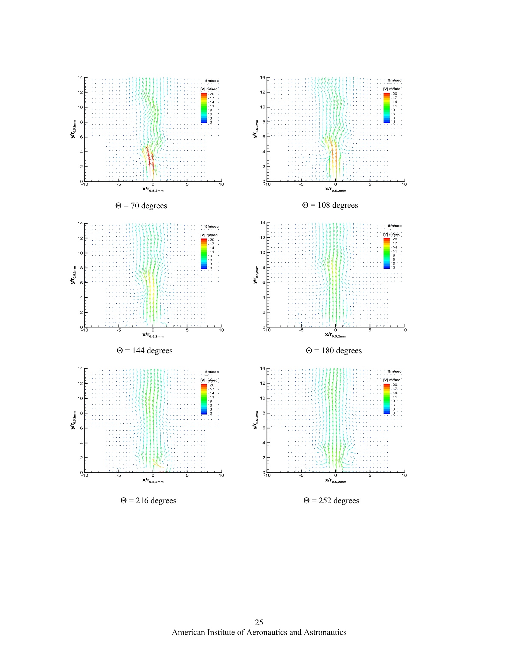
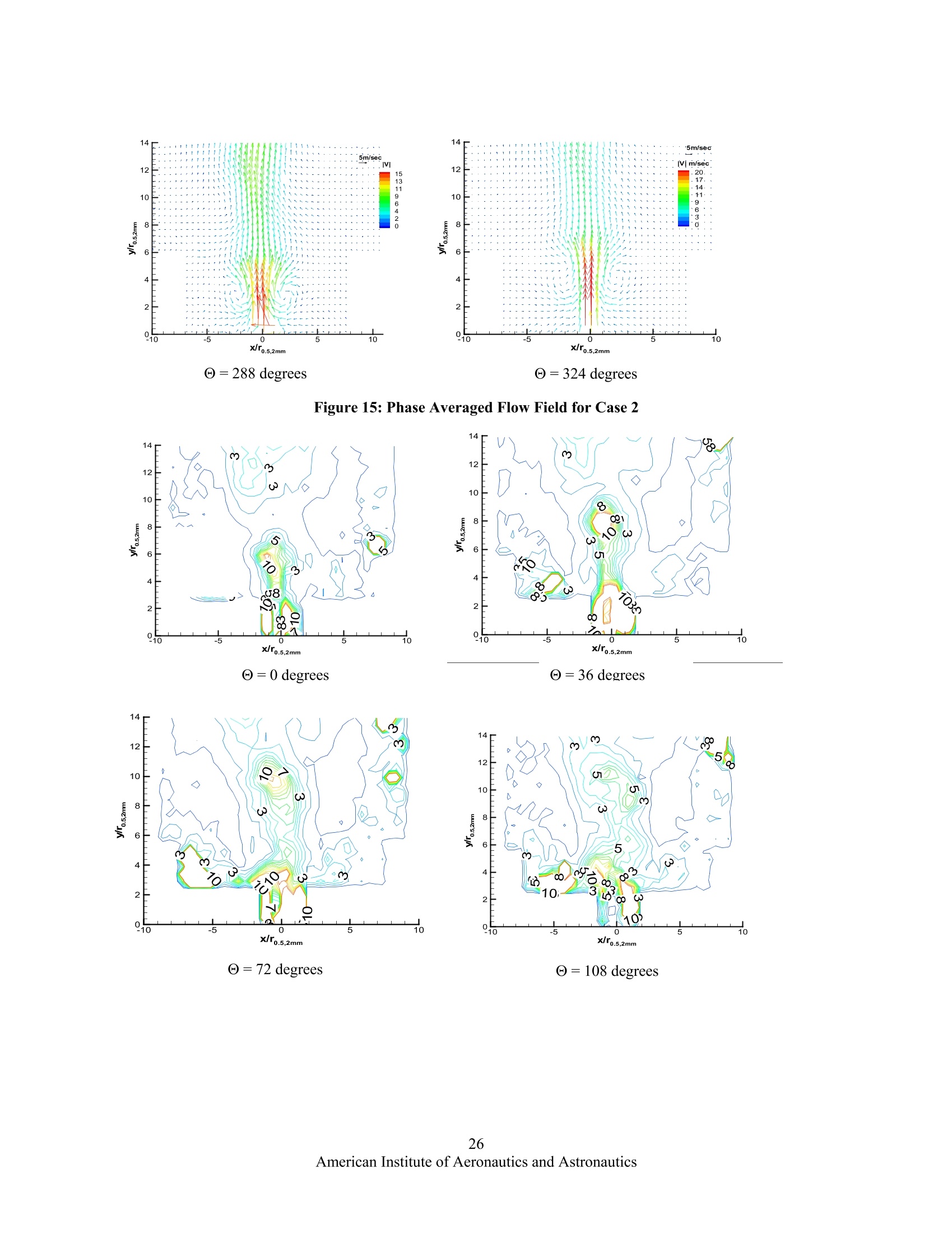
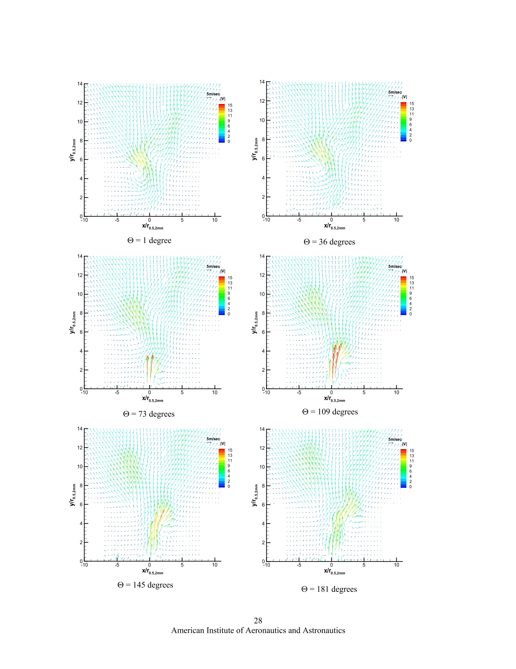
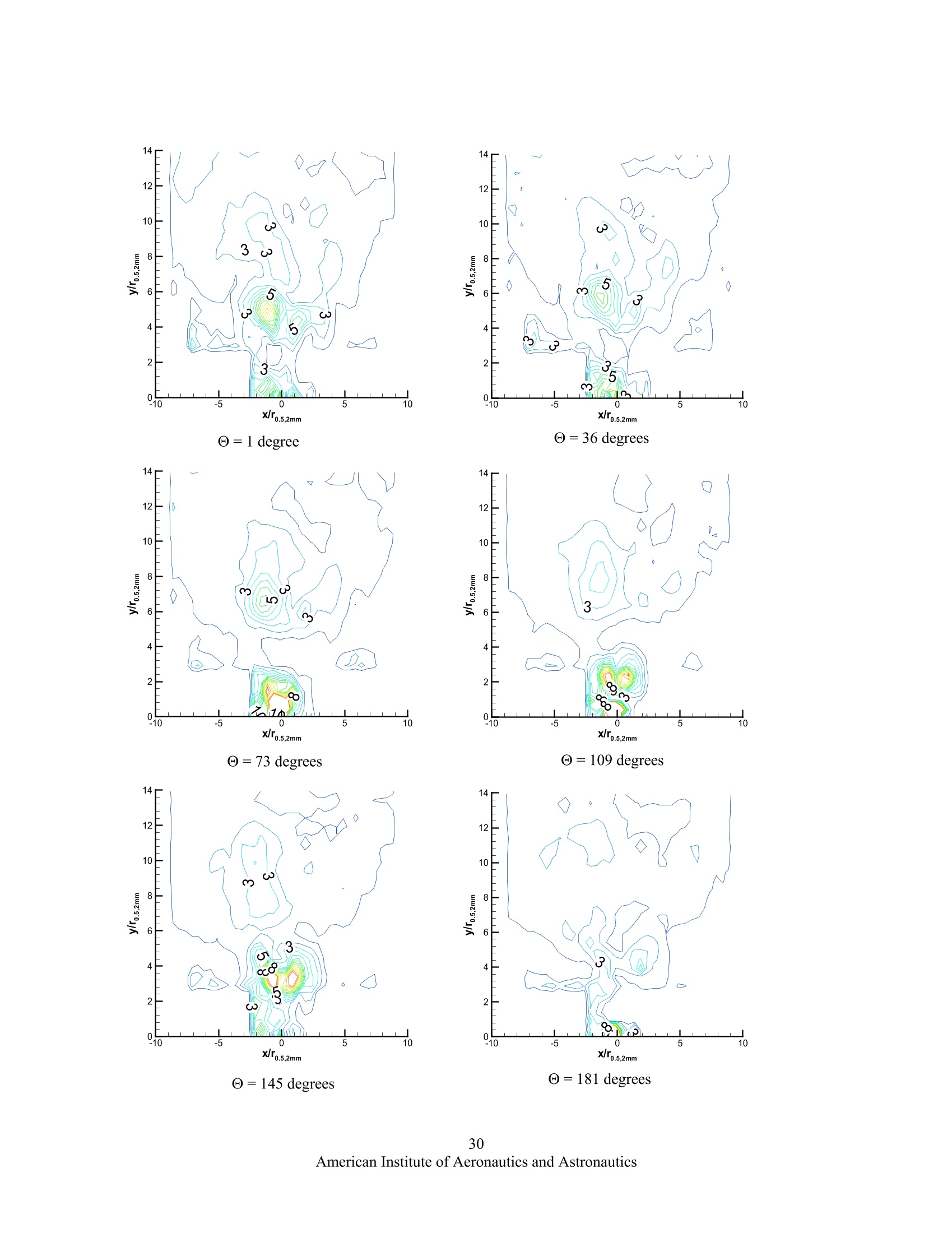
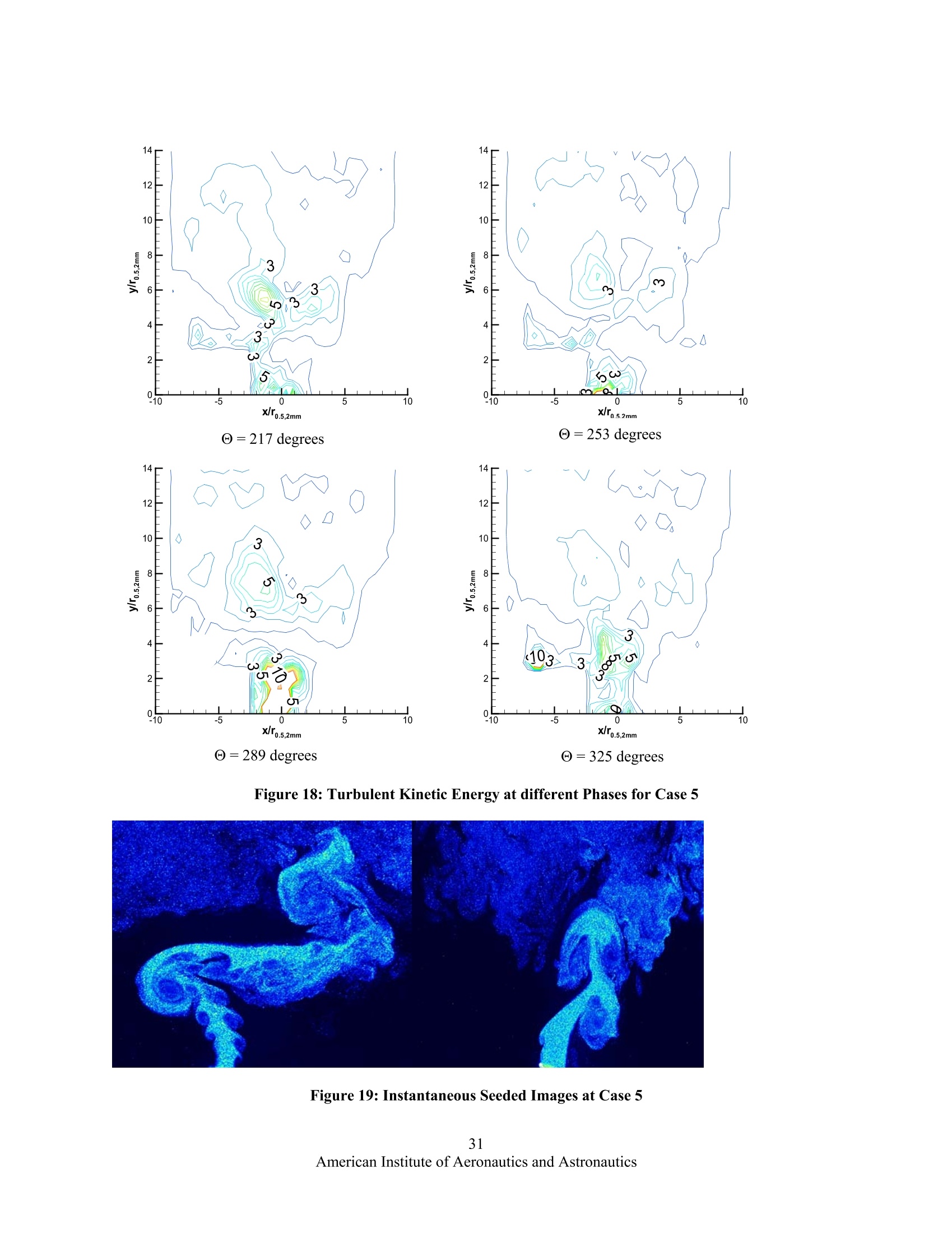
AIAA 2006-48244th AIAA Aerospace Sciences Meeting and Exhibit9-12 January 2006,Reno, Nevada Flow -Structure Interaction Effects on a Jet Emanatingfrom a Flexible Nozzle S.Murugappan", R.R. Lakhamraju, E.J.Gutmark* Department of Aerospace Engineering and Engineering Mechanics University of Cincinnati, Cincinnati, OH-45219, USA and S. Khoslas Department of Otolaryngology-Head Neck and Surgery University of Cincinnati, Cincinnati, OH-45267, USA Pulsed jets have found a wide variety of applications in the area of flow control duringthe recent years. The goal of the current study is to identify the flow field and mixingcharacteristics associated with an incompressible circular jet through a flexible nozzle. Theflow was self-excited over a range of conditions and produced a pulsatile flow. The frequencyof excitation was found to be between 150-175Hz. Phase-locked and time averaged 2DParticle image Velocimetry (PIV) was used to study the dynamic characteristics of the flow.The flow field shows that two different modes could be excited depending on nozzlecharacteristic. The flapping mode was associated with alternate shedding of vortices. Thisintroduces strong steering of the jet to one side or the other. Turbulence, Jet spread andentrainment characteristics were far more superior to the non-flapping or a pulsed jet. Thesecond mode which was a non-flapping mode is associated with the formation of a counterrotating vortex pair. The turbulence associated with both these modes was convected alongwith the vortical structure in the flow. The jet vortices formed by the self-excited flow werenot just convected by the flow, but these determined the flow field and mixing characteristicsof the jet. I. Introduction ince Crow anSid Champagne [1] investigated the orderly structure of turbulent jets, the dynamics of pulsed jetshas generated great interest in the scientific community. Crow and Champagne [1] showed the presence of jetcolumn instability at the end of the potential core of the jet. This instability was characterized by a non-dimensionalfrequency (Strouhal number) defined as fD/U where f is the frequency at the end of the potential core, D is the jetdiameter and U is the exit velocity. The instability was excited at a St=0.3. Later Gutmark and Ho [2] showed thatmost amplified frequency or the preferred mode of a subsonic jet occurs at a normalized frequency (Strouhalnumber) in the range of 0.25-0.5 depending on the experimental facility. Forcing a subsonic jet at the preferredmode frequency could dramatically alter its growth rate [1-3]. The jet mixing layer can be greatly manipulated by avery low level of forcing level depending on the forcing frequency. The initial instability frequency is characterizedby a Strouhal number Ste=f*O/U in the range of 0.009-0.018 [3,4] where f is the initial instability frequency, (Uo) isthe jet exit velocity and Qis the initial shear layer thickness. Forcing at the initial instability can stabilize the shearlayer and prevent growth, while forcing at lower frequencies (subharmonic forcing) accelerates vortex formation andspreading rate. In subsonic flows, the growth rate is dominated by vortex dynamics, as vortical structures interactthrough subharmonic pairing [3]. Exciting a jet at a frequency which is lower than the preferred mode causes the ( Visiting Research A ssistant Professor, Corresponding Author. ) ( ' Graduate Student. ) ( P r ofessor, Ohio regents E minent Scholar, Associate F ellow AIAA ) ( ° Assistant Professor. ) vortices to coalesce together in a process called collective interaction thus further enhancing the spreading rate insubsonic jets [4]. A combination of axial and helical excitation has been used to generate a unique class of flows known asbifurcating and blooming jets [5]. The axial forcing causes the shear layer to roll up into distinct vortex rings at theforcing frequency. The helical excitation perturbs the rings radially, producing a small eccentricity in the ringalignment. This initial eccentricity is amplified by mutual ring interaction leading to dramatic changes in jetevolution. When the axial frequency is exactly twice the helical excitation, the jet bifurcates into two distinct jetswith successive rings moving alternately on one of the two separate trajectories. When the ratio of the axialhelical toexcitation is non-integer, the jet “bloom”in a shower of vortex rings called blooming jet. Both bifurcatingand blooming jet has been observed to produce enhanced spreading and mixing [4]. Non-circular jets were widely used as a flow control technique for aerospace applications primarily due to theirmore unstable nature when compared to their axisymmetric counterparts. Flow instabilities, self-induction, vortexstretching, vortex evolution, interaction and reconnection, and fine scale turbulence augmentation become thedominating flow characteristics in non-circular jets. A comprehensive review of flow control with non-circular jetsis provided by Gutmark and Grinstein[5]. A brief discussion of a elliptical and rectangular jets which is morerelevant to this study is given below. The large scale mixing of elliptical and rectangular jets was found to be substantially larger than circular jet dueto the axis switching associated with the self-deformation of elliptic vortices [5]. Gutmark and Grinstein [5]indicatethat the mechanism of self-induction was more important in an elliptical or rectangular jet than the vortex interactionand merging that are dominant in circular jets. Austin [6] measured nearly equal mass entrainment between a forcedand unforced elliptical jets. Husain and Hussain [7] studied controlled excitation of elliptic jets. They observed thatthe near field turbulence, jet spread and locations of switching of major and minor axes could be dramatically alteredby forcing. They also identified that the ‘preferred mode’of the elliptic jet with moderate aspect ratio scales with theexit equivalent diameter. Schadow et al [8] conducted studies on elliptic ducted air jets. They excited the ellipticaljets with acoustic resonant pressure waves of the duct. They found that the maximum mixing was achieved when theforcing frequency was reduced to the range of preferred mode frequency. Husain and Hussain [9] studied a self-excited elliptic jet. The 2;1 aspect ratio self-excited whistler elliptic jet displayed no axis switching phenomena, butthe near field mass entrainment was found to be 70% greater than the non-whistler elliptic jet. They attribute this tothe evolution of the secondary counter rotating vortex pair which induces tearing of the primary vortices increasingthe jet spread and mixing that could not be obtained in a circular or elliptic jets without a collar. In summary, the flow dynamics in a circular jet was found to be governed by the jet vortical structures.Manipulating these vortical structures through forcing could be used to affect the shear layer growth rate and mixingcharacteristics, where as in non-circular jets, asymmetric vortex formation and the self-induction process seem togovern the flow field. Forcing non-circular jet has also found to be beneficial for flow control application. Flowmodulation of circular or non-circular geometries has found a wide variety of applications such as in jet noise, heattransfer, combustion and mixing control and thrust vector control. The following section deals with a special class ofpulsatile flows where the flow is self excited through structural deformation. These flows are also rich in vorticalstructures and provide lot of interesting flow features, but the literature in this area is sparse and the current study isan effort in this direction. A few of the engineering areas where flow over flexible walls has been studied aresummarized below. Kumaran [10] conducted stability analysis of laminar flow in flexible tubes and channels. He observed threedifferent instability modes. They were primarily governed by the Reynolds number; a non-dimensional parameter,Z(=elastic force/Viscous force). He also identified the critical Reynolds number that triggered the viscous, inviscidand wall mode instability as a function of數. Sinha [11] used actuated active flexible wall transducer for controllingboundary layer separation. Micro-flexural vibratory actuation at selected regions of the transducer flexiblemembrane was excited at different frequencies to delay separation. The transducer uses the pre-separation velocitygradient at the point of actuation to amplify the micro vibratory stimuli and cause it to modulate the pressuregradient. This subsequently promotes reattachment by enhancing mixing in the inflectional velocity profilesdownstream. Flexible filaments have been used by Bhat et al. [12] to control mixing and noise characteristics in jetnoise applications. The centerline velocity and turbulence intensity was reduced by up to 25% with flexible filament.Their acoustic results showed that the low and mid-frequency noise was reduced with filament at all measuredangles. Greenhalgh et al [13],Lorillu, O. et al [14] studied aerodynamic properties of a two dimensional flexible airfoil. It has application in aerodynamic wing, sail and parachute design. These have primarily focused on validatingcomputation with experiments, improving aerodynamic efficiency and extending stall margin for low speed highangle of attack operations. Almost all vessels carrying fluids within a living body are flexible, and interactions between an internal flow andwall deformation often underlie a vessel's biological function or dysfunction. These interactions involve a rich rangeof fluid-mechanical phenomena, including nonlinear pressure-drop/flow-rate relations, self-excited oscillations ofsingle-phase flow at high Reynolds number and capillary-elastic instabilities of two-phase flow at low Reynoldsnumber. A comprehensive review in area of biomechanics of flexible tubes is provided in [15]. The current study investigates the flow dynamics of a flexible elongated nozzle. The flow field of a flexiblenozzle has many similarities to that of pulsatile jets. It is in fact a special case of the unsteady jets where the nozzleis allowed to deform. The flow is self excited and the pulsations are periodic. IL. Experimental Setup The flow entering the flexible nozzle from the rigid tube is fed by a compressor which can produce a maximumflow rate of 2500 cc/sec at 35 psi. y and x refer to the stream-wise and span-wise directions (Refer figure 1 and 2).The origin is located at the center of the nozzle (x=0,y=0)..Pressure regulator, thermocouple, electronic pressuregages, mass flow meter and an electronic control valve were mounted upstream to monitor and regulate the flow.The air flow was seeded in a settling chamber with olive oil particle for flow measurements and visualizations.Typical particle diameter of the seed used for the Particle Imaging Velocimetry (PIV) measurements was in therange 1-5 microns. The maximum Stokes number (S&) is given by where t, and tr are the particles and flow time scales, respectively. tf=8/Uc where pp is the particle density, D,is the particle diameter, u is the absolute viscosity of the air, Lm is the lengthof mean free path of the molecule, 8 is the shear layer thickness and UcL is the velocity on the centerline. Computations of Samimy and Lele [16] for a particle-laden compressible mixing layer suggest that the Stokesnumber defined using vorticity thickness should be less than 0.5 for correct flow visualization. Using theincompressible result that the visual thickness is about twice the vorticity thickness, the Stokes number using theshear layer thickness should be below 0.25 [17]. The upper bound of Stokes number in the present experiments was0.018. Non-intrusive measurements of the velocity field were made using 2D PIV. The LaVision Imager Intensecamera used to capture the images has a resolution of 1537 (H) and 1034 (V) pixels with size 6.45 x 6.45 um and amaximum frame rate of 10Hz. It has 65% quantum efficiency at 532 nm with a 12 bit digital output. The camerawas fitted with a 532 nm narrow bandpass filter with a Nikon 105 mm F/2.8 lens for all the cases. A dual Pentium 4processor with a 1GB RAM was used to control the data acquisition. To illuminate the flow field, a frequency double Nd-YAG laser with dual cavity (New wave Research Solo-PIV)was used. The output was 50mJ/pulse at 532 nm at apulse rate of 10Hz. The time At, between the two laser pulseswas kept constant at 8 usec. The arrangement of the laser and the camera is shown in figure 3. The viewing plane (x-y) was aligned with the nozzle mid plane in the flow direction. DAVIS (PIV Data Processing Software fromLaVision) software was used for post-processing of the images to extract velocity vectors. A cross- correlationtechnique was employed for extracting the vectors. Each of the images was divided into interrogation windows. Thecorrelation function operated on the intensities inside each interrogation windows and passed through the completePIV recording with a specified window shift. The evaluation yielded one velocity vector for each interrogationwindow. For a detailed description of the extraction technique refer to Kompenhans et al, [18]. Both time-averaged and phase-locked PIV images were acquired. For phase-locked PIV images, a microphonesensor was placed at x-y plane 65 degrees from y=0 line at a distance of x=-3.5 inches (Fig. 2). The microphonesignal was inputted to a Dspace (Model DS1104) real time signal processor. The signal was bandpass (Type: 4"Order Butterworth) filtered with a lower and upper cut off frequencies of 60 and 400Hz. The filtered signal was thenamplified before being sent to a threshold detector which outputs a square wave (-5 to 5 Volts) depending on theinput signal. It is positive ifthe input is greater than the threshold and negative if the input is lower than threshold.The threshold was set high enough so that the trigger was not generated due to noise. This trigger signal was sent tothe Davis software. Different delays were then generated in the synchronizer to scan through one entire microphonecycle. 100 images were acquired at each phase with a total of 10 phases. Time averaged images were constructed byseparately obtaining 200 images at each case. There was no time correlation between these images. The time averaged sequence was not constructed from the limited phase averaged images (10 phases), since non-correlatedflow field obtained from 200 images provided a better estimate of the flow field turbulence A. Operating Conditions Table 1 shows the six different operating conditions that were investigated. Figure 4 shows the variation ofnozzle parameter as a function of excited frequency. The frequency was found to increase with increasing mass flowbut the change was minimal when compared to the dependency on the nozzle parameter. A sample microphonespectra (Case2) is shown in figure 5. I. Results and Discussions A. Time Averaged flow field The time averaged flow-fields computed from 200 instantaneous PIV images for the six different cases is shownin figure 6a-f. The first 2 mm of the measurement had strong reflection from the flexible tube when the PIV imageswere acquired, hence all the data analysis was done past 2mm. Due to lack of any proper normalization, the jet half-width at a stream-wise distance of 2mm(r 0.5,2mm )has been used as a normalizing factor. Flow field is symmetric atthe high flow rate condition (m=60slpm). A slight deviation to the right is perceptible at the low flow rate conditionpossibly due to ambient drift currents in the room. Precautions were taken to keep them as small as possible. In allthe cases entrainment of the ambient fluid into the jet is clearly visible. The steady fields provide some interestingfeatures as the nozzle parameter and the mass flow are varied. The jet spread is wider at the lower mass flow whencompared to the higher flow rate condition. For the same low mass flow rate, case 3 and 5 shows that the jet splitsinto two separate streams downstream. The jet core is found to be coherent below y/r 0.5,2mm≤5.2 for case 3 butfurther downstream the jet is found to split into two separate jets which induces a low velocity region in the jet core.The jet split was found to occur earlier y/r o.5,2mm4 for case 5. Another interesting feature observed in case 3 and 5are the superior entrainment of the ambient stream which was not found in case1. Casel shows a coherent jet withno observed jet splitting over the entire measurement range. The higher mass flow rate (=60slpm) doesn’t show anyjet split in the time averaged flow fields for all the cases. However the jet width was found to be wider for case 4 and6 when compared to case2. Sample instantaneous flow field is presented in figure 7 and 8 for cases 3 and 1respectively. Figure 7 a shows the evolution of a single vortical structure on the left side of the jet, at other instancesthe vortex structure was found to be present on the right side of the jet (refer 7b). The presence of these two separatestructures, formed at different instances in time, steers the jet to one side or the other indicating that the jet flaps.The trajectory ofthese vortical structures, indeed control the shape and spread of the jet. The instantaneous flowfield in case 1 shows that the two counter rotating vortical structures on either side of the jet are at the same stream-wise location. In an impulsively started turbulent jet, the entire velocity field around the jet head shows a toroidalvortex which surrounds the jet head. This toroidal vortex is called a starting vortex and it induces a largerecirculation zone. There is a transient period between the passage of the vortex and the attainment of steadyentrainment from the ambient stream [19]. The instantaneous image for case 1 in figure 8a shows the evolution oftwo counter-rotating vortex pair from a starting vortex. These two vortical structures are symmetrical in nature. Alsonoticeable in figure 8a is the large spread of the jet in the lateral extent at y/ro.5, 2mm =6.4 which arises due to thestarting vortex. Figure 8 b also shows the remnants of the earlier vortex at y/fo.5,2mm =8.. Figure 9 shows the jet halfwidth at different stream-wise locations. Half-width is defined as the distance where the local velocity is of thepeak velocity. Both the x and y coordinates of the plot are normalized by the jet half width at y=2mm. Included inthis plot are published data points from other unsteady jets: Cater and Soria [20] of a zero net mass flux jet at a non-dimensional Strouhal frequency (fD,/U=0.0015, where f is the frequency, D, is the orifice diameter and U, is themomentum flow velocity), Mi et al [21] from a flapping rectangular jet (f=100Hz) and Bremhorst and Hollis [22] ofa subsonic pulsed jet (f=10Hz), Bera et al [23] from a purely alternating (synthetic jet) slit jet forced at f=200Hz,Ho and Gutmark [24] from an elliptic jet (jet spread along the minor axis) with an aspect ratio of 2:1. As observedfrom the time averaged flow field cases 3 and 5 shows a rapid increase in slope past y/ru/2, 2mm. This arises from thejet flapping that causes large entrainment with increased jet spread. Increasing the mass flow rate in the flappingcases 3 and 5 suppresses the jet flapping causing the jet to shed symmetrical counter rotating vortex pair withoutsteering the jet to one side or other. This leads to reduced jet width. For the non-flapping cases 1 and 2, increasingthe mass flow suppresses the spreading rate of the jet. In a steady jet, the shear layer growth rate of the jet isgoverned by the length scales of the eddies. The size of these eddies is inversely proportional to the velocity, hence a higher velocity would suppress the growth rate in the near field of the jet. Figure 10 shows the centerline velocitydecay normalized by the velocity at stream-wise location y=2mm.As in the jet half-width plot the flapping casesshow an accelerated decay of the centerline velocity. For cases 3, 5 and 6 the evolution of V/Vc with downstreamdistance y is more complex, because of the presence of intermediate low velocity regions at the center due to the jetflapping. Such behavior is also observed in the near field of a synthetic jet [20]. Clearly the spreading rate,entrainment and large scale mixing associated with the flapping cases is much higher than the non-flapping cases. The mean stream-wise velocity profile is presented in figure 11a-d for cases1, 2, 5 and 6. These velocities arenormalized by the maximum axial velocity at each stream-wise location and the radial distance was normalized bythe jet half-width. The jet is symmetric, hence the plots are shown along one radius. The present data are comparedhere to a subsonic circular jet measured at a distance of 40-97 diameters from the nozzle [26].It is interesting to notethat even though the data covers only the near field of the jet, case 2 shows that the stream-wise velocity componentcollapses into one curve, though it does not completely follow the subsonic circular jet curve. Since the jet hasdifferent initial conditions, it is possible that it might have a different asymptotic state than that of a subsoniccircular jet. Case 5 clearly shows the peak velocity to be shifted away from the centerline past y/ro.5,2mm5. Themean jet velocity remains split over the entire measurement range. Figure 12 a-c shows the mean lateral velocity component for cases 1, 5 and 6. Case 2 is not plotted, since thespan-wise component was less than 5% of the mean stream component which was within the measurement error.This indicates that the jet has minimal span-wise spread in the lateral direction over the measurement domain incase2. The maximum magnitude of lateral component at y/ro.5,2mm5 is almost twice for case 5 as compared to case1. This arises to the flapping associated with case 5 that introduces two separate streams. Plotted in figure 12 b is thedata published by Mi et al [21] for a flapping jet. They observed that the mean velocity profiles collapsed past y/D≥9and the magnitude of the span-wise component of flapping jet was almost twice as large as the non-flapping jet.Span-wise velocity profiles from a synthetic jet by Bera et al [23] is also plotted in fig. 12b. The magnitude of thespan-wise component is higher than the flapping jet case from Mi et al [21]. This indicates that different asymptoticstates exist depending on the initial conditions of the jet and these might never asymptote to the subsonic circular jet.It is also worthwhile to note that the effect of these initial conditions persist far downstream altering the jetcharacteristics. It could also be observed that both flapping and pulsating jet (such as synthetic jets) have a muchlarger radial spread when compared to a steady in compressible circular jet. The lateral velocity component showsclearly that in the near field self-similarity is not attained as expected,even when the stream-wise component maylead to such conclusion in certain cases. The stream-wise turbulence components are plotted in figure 13 a-d for case 1, 2, 5 and 6. Case 1 and 2 areapproaching the circular jet scaled profile past y/ro.5,2mm13. Even the flapping jet case 5 seems to asymptote to thesubsonic circular jet. Case 6 shows variation in V'profiles over the measurement range and far from reaching self-similarity. The flapping jet case from Mi et al [21] is added to figure 13c. They observed that the magnitude of theflapping jet stream-wise turbulence component was 2.5 times the non-flapping case for 9sy/D≤34. Plotted in figure13 c is the data from Bera et al [23]. The magnitude of the stream-wise fluctuation was almost twice the magnitudewhen compared to the current data sets. This indicates that such large fluctuations might be possible in the near-fieldof transient flows, but they decay farther downstream. The Reynolds stress for cases 1, 2 , 5 and 6 are shown in 14a-d. The data from Mi et al [21] also show a twice higher U'V' levels from the flapping jet as compared to their non-flapping case. As in the V'profiles for case 6 the Reynolds stress shows large variations and yet to reach similarity.Also, interesting is the rapid drop off in the max U'V'levels from 16% to 1.5-25 within 2 ro.5,2mm. High levels of U'V'is another consequence that arises due to the large fluctuations in the stream-wise turbulence. This could besupported from phase averaged turbulence profiles shown (fig 16 and18.). They indicate that both TKE show similartrends, i.e. they increase with the formation of the starting vortex and decay as the vortical structure gets convecteddownstream. B. Phase Averaged Flow field Phase averaged flow field was acquired at 10 phases of the microphone cycle. A total of 100 images wereaveraged at each phase. Flow field for Case 2 and 5 are presented at different phases in figure 15 and 17. Thecorresponding turbulent kinetic energy in absolute units (m /sec) is also shown in figure 16 and 18 for these cases.All the length dimensions in the plots are normalized by the jet half width at y=2mm.For case 2, the formation ofthe counter rotating vortex pair and it convection downstream is evident. The vortex pair forms at two differentphases during the cyclic motion of the tube’s exit. The first pair is detected between 36<0<70. The second vortexpair is identified between 186<0<216. Both these vortex pairs are convected downstream in a symmetric manner.For case 5, two separate vortex pairs are not evident. The jet forms one vortex either on the right or left. A second one is formed on the other side 180 degrees out of phase. Both the flapping case 5 and non-flapping case 2 hadsimilar convective speed of the vortical structure. They were found to be 0.44 and 0.42 for case 2 and 5 respectively.Instantaneous images generated by a laser sheet illuminating seeding particles are shown at the formation of thevortex pair in figure 19 and 20 for case 2 and 5. For the flapping case, a sample images are shown which display thejet vortex formation either to the left or right. The instantaneous seeded images of case 2 show a symmetricbehavior. The TKE is generated at the formation of the vortex pair and is convected downstream along with it. Thehighest TKE is formed at the incipient stages of the vortex formation. As it is convected downstream, the TKEdecays. For case 5, the turbulence is 10 % of the mean kinetic energy at the vortex formation and it drops down to3% at y/ro.5,2mm=10. For case 2, the turbulence is only 4% at the vortex formation and drops to almost 2% at y/ro.5,2mm=10. This indicates that the flapping case is associated with higher turbulence production. IV. Conclusions 2D PIV was used to study the flow at the exit of a flexible tube nozzle. The frequency of excitation was found tobe a function of the nozzle parameter. The frequency range was found to be around 150-175 Hz. Both time averagedand phase locked PIV measurements were used to study the 2D flow field. It was observed that the jet had twodifferent flow patterns. At the flapping mode, phase averaged images indicated that a single vortex was shed on oneside, which caused the jet to steer to that side. During the second half of the cycle, the vortex formed on the alternateside. Time averaged analysis showed that the flapping motion induced a strong jet spread and high entrainment. Themaximum jet spread was approximately 3 times higher for the flapping mode case as compared to the non-flappingcase. The normalized mean radial velocity was found to be almost an order of magnitude higher for the flappingcases when compared to a subsonic circular jet. The jet spread observed with the flapping modes of the flexiblenozzle was found to be substantially higher than the pulsed and flapping jet found in previous literature. Theturbulence and Reynolds stresses were also found to be much higher than steady or pulsating jets. The second modewas a symmetric mode where a counter rotating vortex pair was formed. These vortex pairs resulted in a much lowerjet spread when compared to the flapping jet cases but still higher than pulsating jets published in literature. References 1. Crow, S.C. and Champagne, F.H., Journal of Fluid Mechanics, Vol:48, 547-591, 1971 2. Gutmark, E., and Ho, C.M., “Preferred Modes and The Spreading Rates of Jets”, Physics of Fluids 26: 2932-2938, 1983 3. Ho, C.M. and Huang, L.S., "Subharmonics and Vortex Merging in Mixing Layers”, Journal of Fluid Mechanics, Vol: 119,443-473,1982. 4. Ho, C.M. and Huerre, P.,“Perturbed Free Shear Layers," Annual Review of Fluid Mechanics, Vol. 16, 1984, pp. 365-424. 4. Reynolds,W.C., Parekh,D.E., Juvet, P.J.D., Lee., M.J.D.,“Bifurcating and Blooming Jets,” Annual Review of FluidMechanics,Vol.35, pp. 295-315, 2003. 5. E.J.Gutmark, F.F. Grinstein,“Flow Control with Non-Circular Jets,” Annual Review of Fluid Mechanics, Vol. 31, pp. 239-272,1999. 6. Austin, T.,“The small scale Topology of a 2:1 Aspect Ratio Elliptic Jet,” Ph.D Thesis, Univ. of South Calif. Los Angeles,1992. 7. Husain, H.S., Hussain, A.K.M.F., “ Controlled Excitation of Elliptic Jets," Physics of Fluids, Vol. 26, pp. 2763-2766, Oct1983. 8. Schadow, K.C., E.Gutmark, K.J. Wilson, and D.M. Parr,“Mixing Characteristics of a Ducted Elliptic Jet,” Journal ofPropulsion and Power, Vol. 4, No.4, pp. 328-333, 1988. 9. Husain, H.S., Hussain, A.K.M.F.,“The Elliptic Whistler Jet,”Journal of Fluid Mechanics, Vol. 397, pp. 23-44, 1999. 10. Thaokar, R.M., Kumaran, V.,“Stability of Fluid Flow Past a Membrane,”Journal of Fluid Mechanics, Vol. 472, pp. 29-50, 2002. 11. Sinha, S.K.,“Flow Separation Control with Microflexural Wall Vibrations,”Journal of Aircraft, Vol. 38, No. 3, 496-5032001. 12. T.R.S. Bhat, B.A. Anderson, E.J.Gutmark,“Flexible Filaments in Jets & The Interaction Mechanism,”AIAA Paper 2000-0083,2000. 13. Greenhalgh, S., Curtiss,HCJR, Smith, B.,“Aerodynamic Properties of a two dimensional inextensible flexible airfoil,”AIAA Journal,Vol. 22,No.7,pp.865-870, 1984. 14. Lorillu, O.,Weber, R., Hureau, J., “Numerical and Experimental Analysis of Two-Dimensional Separated Flows Over aFlexible Sail,” Journal of Fluid Mechanics, Vol. 466, pp. 319-341,2002. 15. Grotberg, J.B., Jensen, O.E.,“BioFluid Mechanics in Flexible Tubes,” Annual Review of Fluid Mechanics, Vol. 36, pp.121-147,2004. 16. Samimy M., and Lele, S.K.,“Motion of Particles with Inertia in a Compressible Free Shear Layer,” Physics of Fluids A,Vol.3,pp. 1915-1923,1991. 17. Clemens, N.T., and Mungal, M.G., “A Planar Mie Scattering Technique for Visualizing Supersonic Mixing Flows,"Experiments in Fluids, Vol. 11, pp. 175-185, 1991. 18. Kompenhans, J., Raffel M., Willert, C.,“Particle Image Velocimetry-A practical guide,”Springer, Berlin, 1998. 19. Cossali, G.E., Coghe, A., Araneo, L., “Near -Field Entrainment in an Impulsively Started Turbulent Gas Jet," AIAAJournal, Vol.39,No.6, pp. 1113-1122,2001. 20. Cater, J.E., Soria, J.E.,“ The evolution of Round Zero-Net-Mass-Flux Jets," Journal of Fluid Mechanics, Vol. 472,pp.167-200,2002. 21. Mi, J., Nathan, G.J., Luxton, R.E., “Mixing Characteristics of a Flapping Jet from a Self-Exciting Nozzle,” Flow,Turbulence and Combustion, Vol. 67, pp. 1-23, 2001. 22. Bremhorst, K., and Hollis, P.G.,“Velocity Field of an Axisymmetric Pulsed, Subsonic Air Jet,"AIAA Journal, Vol.28,No.12, pp. 2043-2049,2001. 23. Bera, J.C., Michard, M., Grosjen, N., Comte-Bellot, G.,“ Flow Analysis of Two-Dimensional Pulsed Jets by ParticleImage Velocimetry,”Experiments in Fluids, Vol. 31, pp.519-532,2001. 24. Ho, C.M., Gutmark, E.J.,“Vortex Induction and Mass Entrainment in a Small Aspect Ratio Jet,” Journal of FluidMechanics, Vol. 179, pp. 383-405,1987. 25. Mi, J., Nathan, G.J., Luxton, R.E.,“Centreline Mixing Characteristics of Jets from Nine Differently Shaped Nozzles,”Experiments in Fluids, Vol. 28, pp. 93-94,2000. 27. Wygnanski, I., Fiedler, H.,“ Some Measurements in the Self-Preserving Jet,” Journal of Fluid Mechanics, Vol. 38, part 3,pp.577-612, 1969. flow P-Electronic Pressure Gage (0-30psi) Figure 1: Schematic of the Flow System Figure 2: Photograph of the Flexible Nozzle indicating the x-y-z coordinate system Figure 3: Schematic of the Set up Mass flow Rate, M,(slpm) Frequency Mode Case1 20 151 Non-Flapping Case2 60 153 Non-Flapping Case3 13 169 Flapping Case4 60 173 Non-Flapping Case5 12 171 Flapping Case6 60 175 Non-Flapping Table 1: Operating Conditions 175 Figure 4: Nozzle Parameter Versus excited frequency Figure 5: Microphone Spectra for Case2 6a, Case 1, M=20 slpm 6b, Case 2,M=60 slpm 11 American Institute of Aeronautics and Astronautics x/ro.5,2mm6c, Case 3, M=13 slpm 6d, Case 4, M=60 slpm '5m/sec 14 12 10 9642 E8 6 4 2 10 5 0 -5 -10 0x/ro.5,2mm6e, Case 5, M=12 slpm 96420 6f, Case 6, M=60 slpm Figure 6a-f, Time Averaged Flow field (a) (b) Figure 7 a and b, Instantaneous images for Case 3 (b) Figure 8 a and b, Instantaneous images for Case 1 ·Case1, m=20slpm ,Case2, m=60slpm ▲Case3,m=12slpm XCase4, m=60slpm XCase5,m=12slpm iCase6, m=60slpm +-Cater and Soria,Synthetic Jet, 2002 X Mi et al., Flapping Jet, 2001 OBremhorst and Hollis,Pulsed Jet, 1990 ◇Bera et al,Synthetic Jet, 2001 0]I Ho and Gutmark, Elliptic jet (AR=2:1), Minor Axis, 1987 Gutmark et al, Slot Jet, (AR=3:1), MinorAxis, 1985 (Gutmark et al, Circular Jet,1985 25 y/ro.5,2mm Figure 9: Jet Half-width for different cases Figure 10: Centerline Velocity decay for different cases -+-y/r1/2,2mm=2 Figure 11 a, Case1 Figure 11 b, Case 2 Figure 11 c, Case 5 Figure 11a-d: Normalized Stream-wise velocity at different stream-wise locations -0.1 r/r1/2 Figure 12 a, Case 1 r/r1/2 Figure 12 b, Case 5 Figure 12 c, Case 6 Figure 12a-c: Normalized Span-wise velocity at different stream-wise locations Figure 13 a, Case 1 --y/r1/2,2mm=6 Figure 13 b, Case 2 -+-y/r1/2,2mm=2 -=-y/r1/2,2mm=5 1 -A-y/r1/2,2mm=7 0.9 —-o-y/r1/2,2mm=9 -X-y/r1/2,2mm=11 一.y/D=20 Wygnanski and Fiedler, ' y/D=9-34, Mi et al, 2001, Flapping Jet ' y/D=5, Bera et al, 2001, Synthetic Jet 之0.5 -y/D=2 Lau et al, 1979 米米 米 0 0 2 3 4 5 r/r1/2 Figure 13c, Case 5 Figure 13d, Case 6 Figure 13a-d: Normalized stream-wise turbulence at different stream-wise locations --y/r1/2,2mm=2 Figure 14a, Case 1 r/r1/2 Figure 14b, Case 2 r/r1/2 Figure 14c, Case 5 Figure 14d, Case6 Figure 14a-d: Normalized Reynolds Stress at different stream-wise locations @=0 degrees ω=252 degrees =216 degrees Figure 15: Phase Averaged Flow Field for Case 2 @=72 degrees @=288 degrees Figure 16: Turbulent Kinetic Energyat different Phases for Case 2 Q=36 degrees =109 degrees 14 14 12 12 10 10 5 0 -10 -5 0 5 10 x/ro.5,2mm -10 -5 x/ro.5,2mm @=181 degrees =145 degrees American Institute of Aeronautics and Astronautics Figure 18: Turbulent Kinetic Energy at different Phases for Case 5 Figure 19: Instantaneous Seeded Images at Case 5 Figure 20: Instantaneous Seeded Images at Case 2 American Institute of Aeronautics and AstronauticsCopyright C by the American Institute of Aeronautics and Astronautics, Inc. All rights reserved. merican Institute of Aeronautics and Astronautics
确定


还剩30页未读,是否继续阅读?

产品配置单


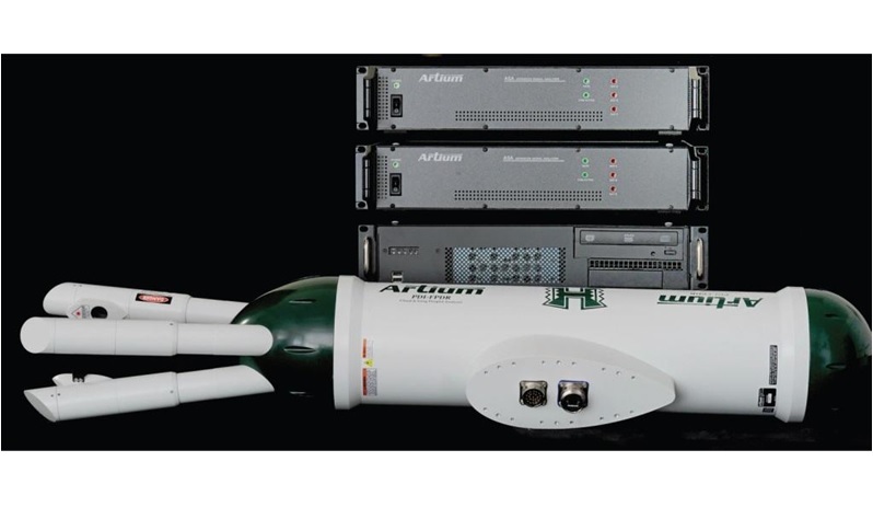
北京欧兰科技发展有限公司为您提供《喷雾,液滴,喷嘴,流体中速度矢量场检测方案(粒子图像测速)》,该方案主要用于其他中速度矢量场检测,参考标准--,《喷雾,液滴,喷嘴,流体中速度矢量场检测方案(粒子图像测速)》用到的仪器有德国LaVision PIV/PLIF粒子成像测速场仪、LaVision SprayMaster 喷雾成像测量系统、Artium PDI-FP 双量程可机载飞行探头
推荐专场


相关方案
更多
该厂商其他方案
更多