


方案详情
文
Active control of a lifted flame is investigated using a coaxial nozzle with magnetic flap actuators arranged on the inner
periphery of the annular nozzle. Near-field vortical structures of the methane/air coaxial jet are manipulated by
introducing disturbances directly to the initial shear layer. Through the manipulation, we can improve flame stability
and flexibly control the liftoff height. It is found that the large-scale vortical structures play a dominant role in the flame
stabilization, and its spatio-temporal evolution is examined with the aid of PIV and LIF to elucidate the control
mechanism. By introducing flap motion driven with a saw-wave signal, we can force the outer shear layer to roll up into
strong vortices in synchronization with the flaps. When the flapping Strouhal number is unity, the lifted flame is
anchored at x/Do ~ 1.5. The strong vortices induced by the flaps produce a blob of flammable mixture, which has
velocity smaller than the flame speed. The possible stabilization mechanism is that the time period of the premixture
supply is balanced with the consumption time of the premixture at the flame base. On the other hand, when the jet is
manipulated by a square-wave signal, the lifted flame is located stably at x/Do ~ 4, which is downstream of the inner
potential core. It is found that vortical structures in the shear layers break into turbulence close to the nozzle exit. The
possible mechanism of the flame stabilization is that the flame propagating upstream is undisturbed due to the absence
of intermittent passage of large-scale vortices.
方案详情

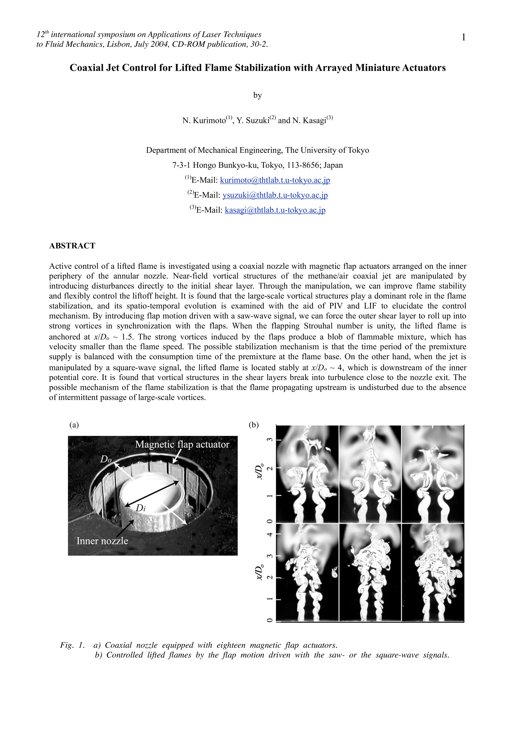
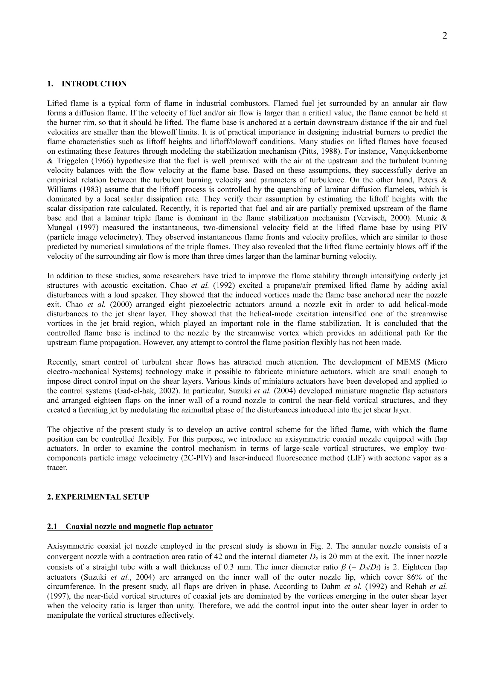
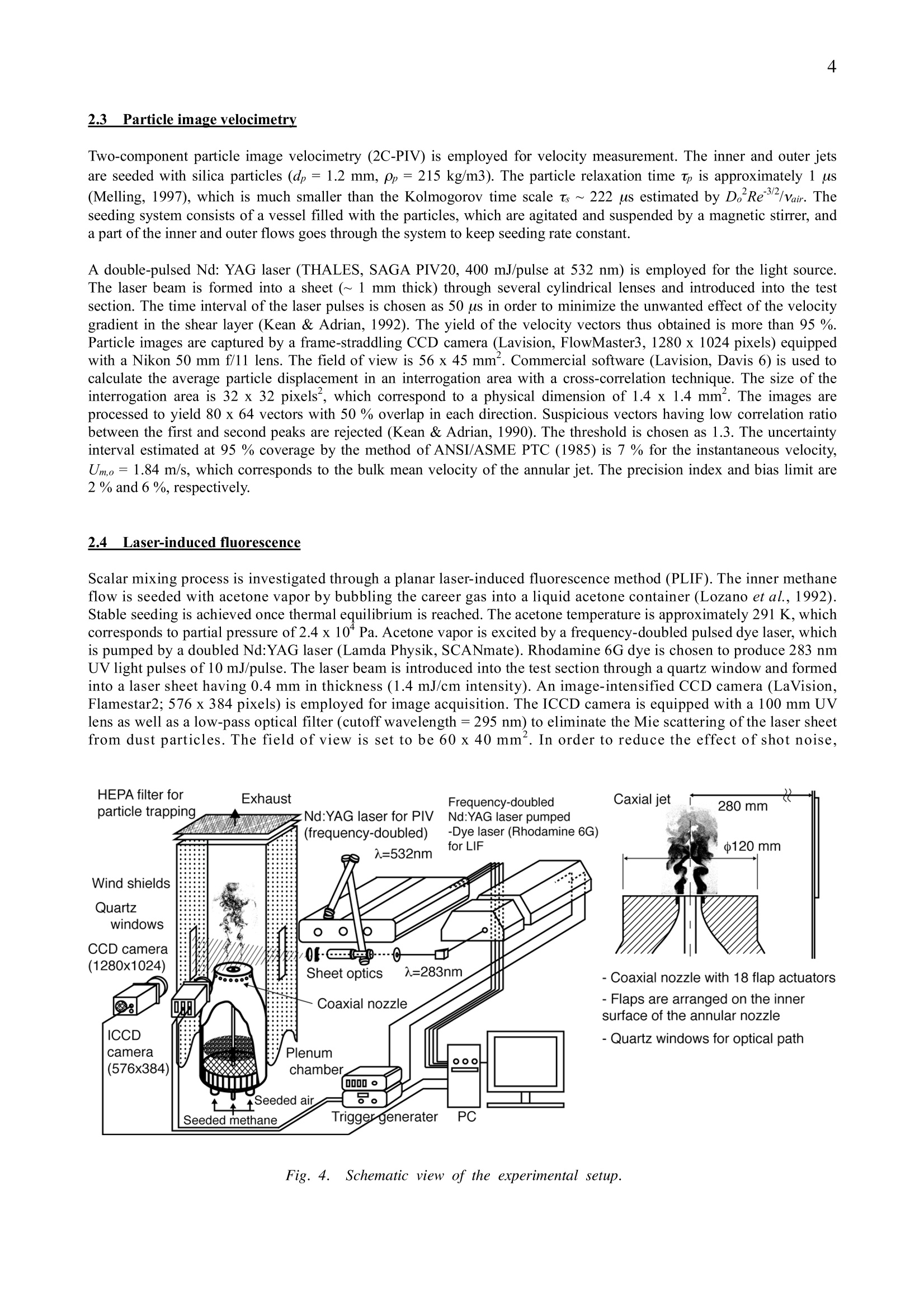
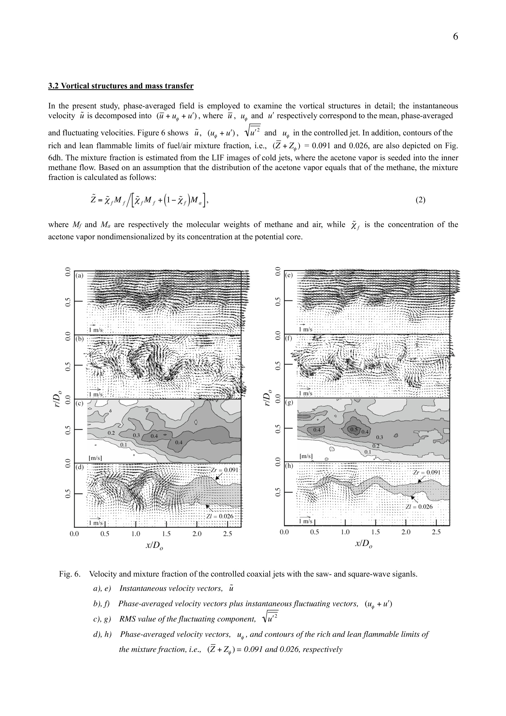
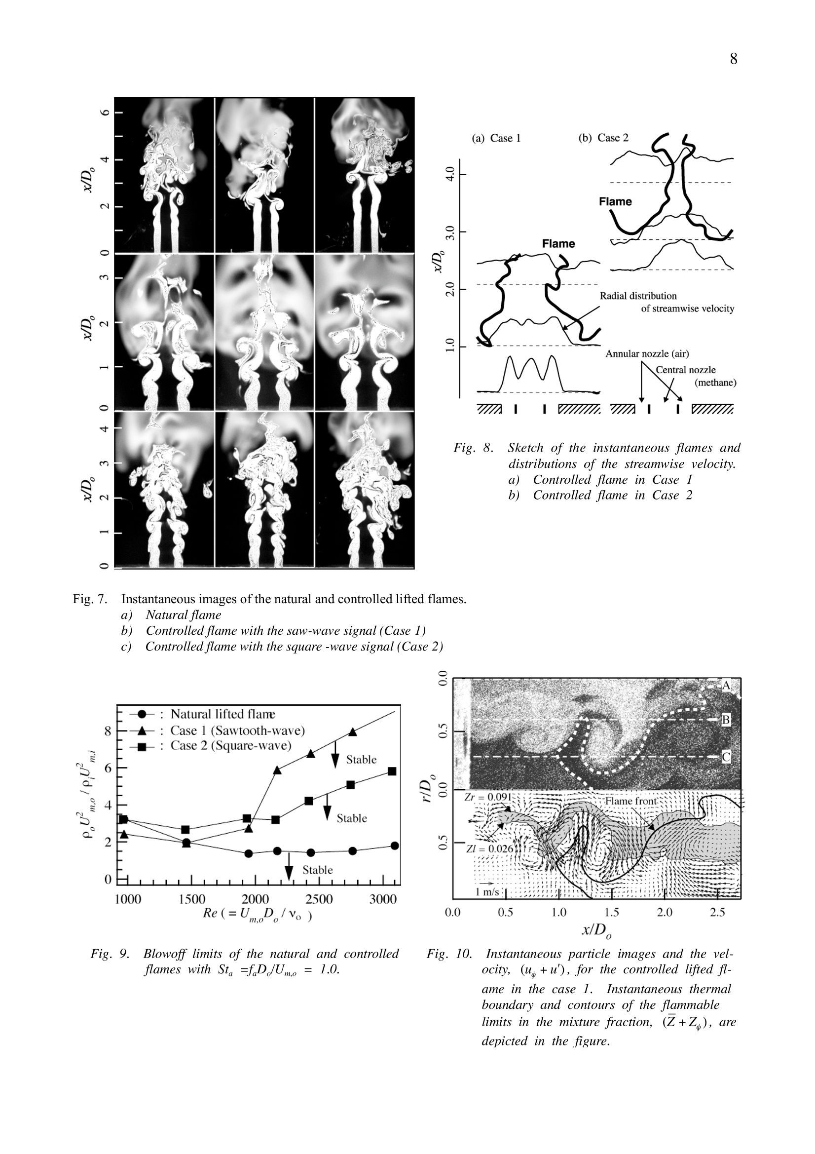
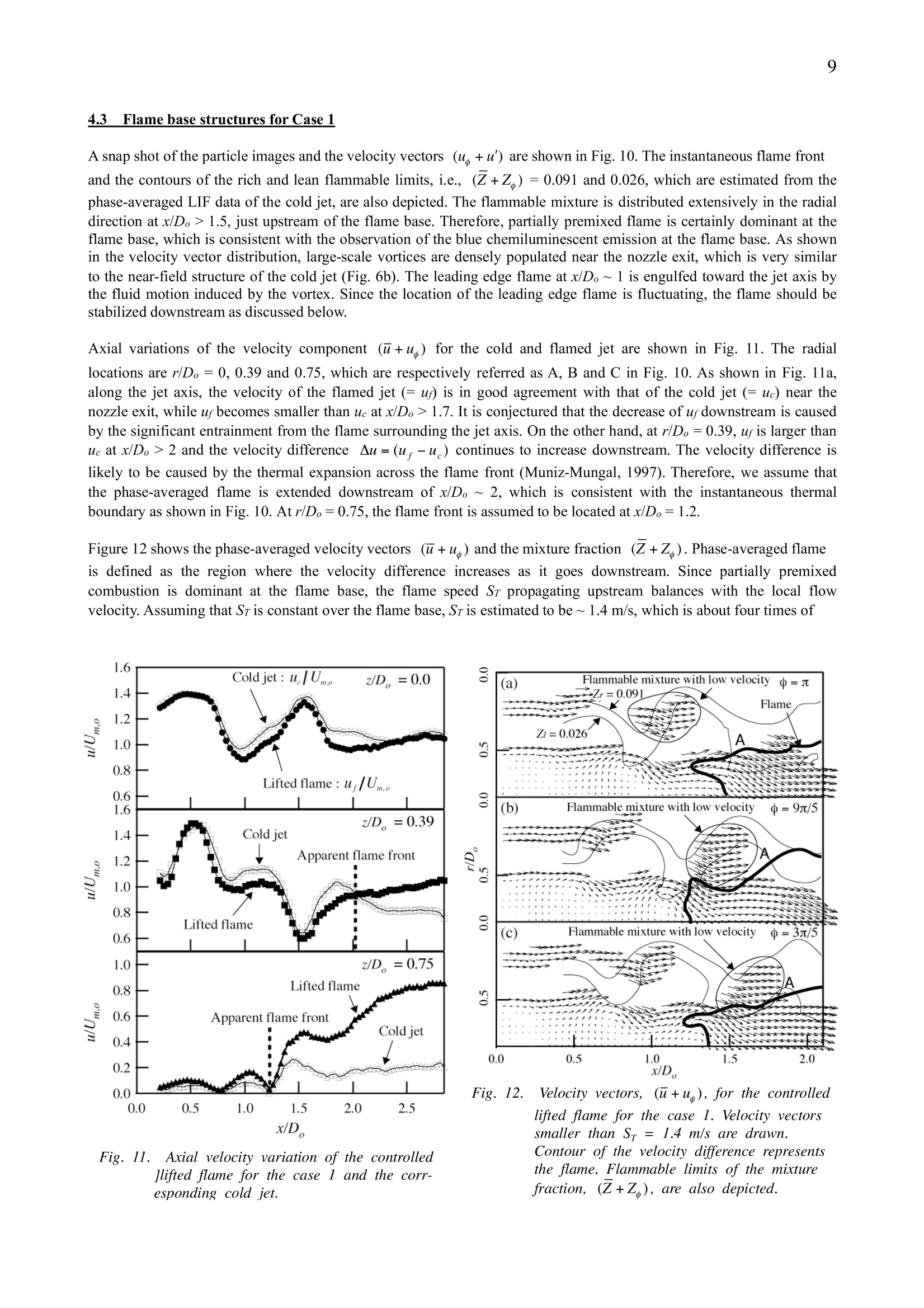
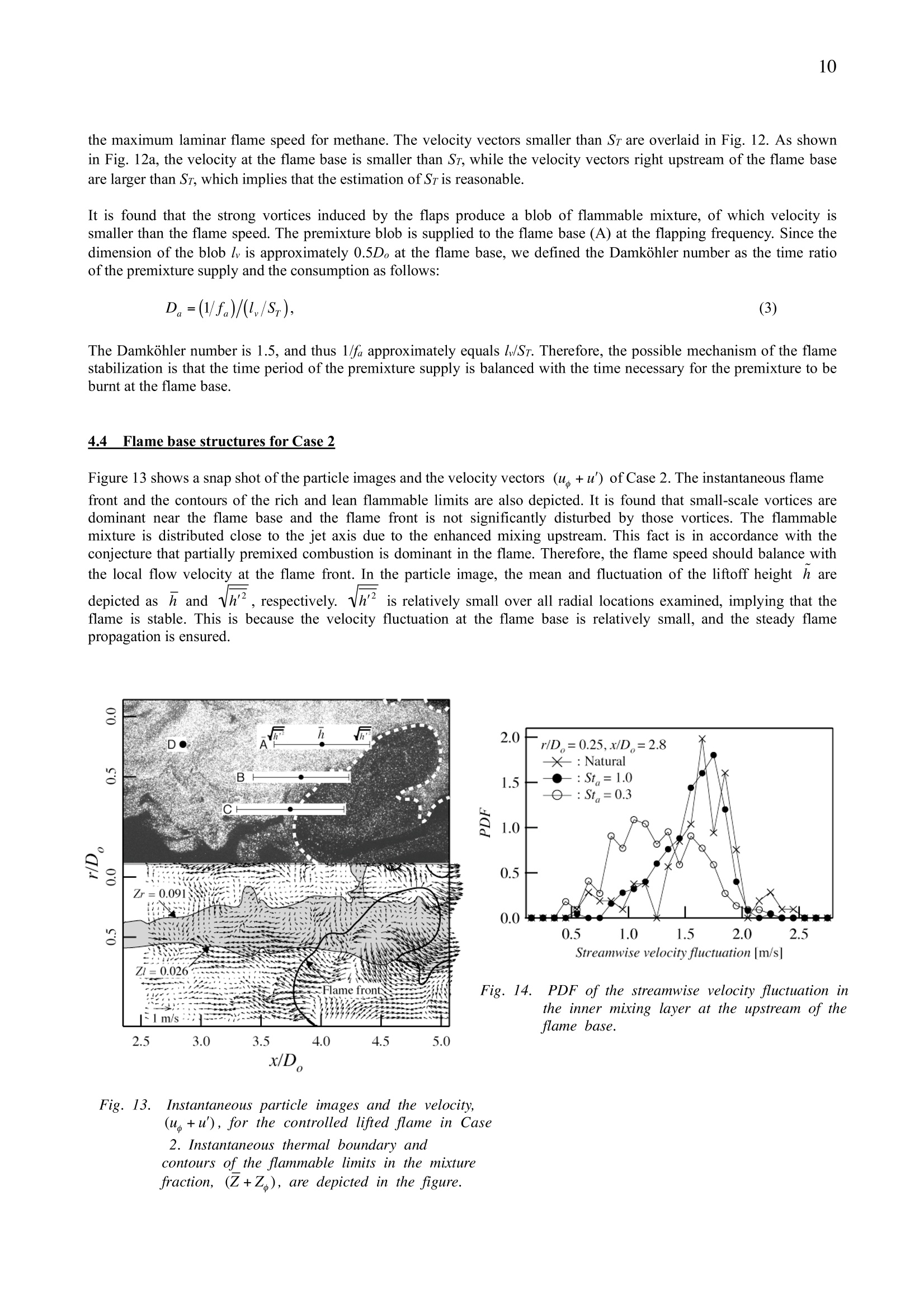
12" international symposium on Applications of Laser Techniquesto Fluid Mechanics, Lisbon, July 2004, CD-ROM publication, 30-2. 2 Coaxial Jet Control for Lifted Flame Stabilization with Arrayed Miniature Actuators by N. Kurimoto", Y. Suzuki"and N. Kasagi3 Department of Mechanical Engineering, The University of Tokyo 7-3-1 Hongo Bunkyo-ku, Tokyo, 113-8656; Japan E-Mail: kurimoto@thtlab.t.u-tokyo.ac.jp E-Mail: ysuzuki@thtlab.t.u-tokyo.ac.jp E-Mail: kasagi@thtlab.t.u-tokyo.ac.ip ABSTRACT Active control of a lifted flame is investigated using a coaxial nozzle with magnetic flap actuators arranged on the innerperiphery of the annular nozzle. Near-field vortical structures of the methane/air coaxial jet are manipulated byintroducing disturbances directly to the initial shear layer. Through the manipulation, we can improve flame stabilityand flexibly control the liftoff height. It is found that the large-scale vortical structures play a dominant role in the flamestabilization, and its spatio-temporal evolution is examined with the aid of PIV and LIF to elucidate the controlmechanism. By introducing flap motion driven with a saw-wave signal, we can force the outer shear layer to roll up intostrong vortices in synchronization with the flaps. When the flapping Strouhal number is unity, the lifted flame isanchored at x/D。~1.5. The strong vortices induced by the flaps produce a blob of flammable mixture, which hasvelocity smaller than the flame speed. The possible stabilization mechanism is that the time period of the premixturesupply is balanced with the consumption time of the premixture at the flame base. On the other hand, when the jet ismanipulated by a square-wave signal, the lifted flame is located stably at x/D。~4, which is downstream of the innerpotential core. It is found that vortical structures in the shear layers break into turbulence close to the nozzle exit. Thepossible mechanism of the flame stabilization is that the flame propagating upstream is undisturbed due to the absenceof intermittent passage of large-scale vortices. Fig. 1. a) Coaxial nozzle equipped with eighteen magnetic flap actuators.b) Controlled lifted flames by the flap motion driven with the saw- or the square-wave signals. 1.1INTRODUCTION Lifted flame is a typical form of flame in industrial combustors. Flamed fuel jet surrounded by an annular air flowforms a diffusion flame. If the velocity of fuel and/or air flow is larger than a critical value, the flame cannot be held atthe burner rim. so that it should be lifted. The flame base is anchored at a certain downstream distance if the air and fuelvelocities are smaller than the blowoff limits. It is of practical importance in designing industrial burners to predict theflame characteristics such as liftoff heights and liftoff/blowoff conditions. Many studies on lifted flames have focusedon estimating these features through modeling the stabilization mechanism (Pitts, 1988). For instance, Vanquickenborne& Triggelen (1966) hypothesize that the fuel is well premixed with the air at the upstream and the turbulent burningvelocity balances with the flow velocity at the flame base. Based on these assumptions, they successfully derive anempirical relation between the turbulent burning velocity and parameters of turbulence. On the other hand, Peters &Williams (1983) assume that the liftoff process is controlled by the quenching of laminar diffusion flamelets, which isdominated by a local scalar dissipation rate. They verify their assumption by estimating the liftoff heights with thescalar dissipation rate calculated. Recently, it is reported that fuel and air are partially premixed upstream of the flamebase and that a laminar triple flame is dominant in the flame stabilization mechanism (Vervisch, 2000). Muniz &Mungal (1997) measured the instantaneous, two-dimensional velocity field at the lifted flame base by using PIV(particle image velocimetry). They observed instantaneous flame fronts and velocity profiles, which are similar to thosepredicted by numerical simulations of the triple flames. They also revealed that the lifted flame certainly blows off if thevelocity ofthe surrounding air flow is more than three times larger than the laminar burning velocity. In addition to these studies, some researchers have tried to improve the flame stability through intensifying orderly jetstructures with acoustic excitation. Chao et al. (1992) excited a propane/air premixed lifted flame by adding axialdisturbances with a loud speaker. They showed that the induced vortices made the flame base anchored near the nozzleexit. Chao et al. (2000) arranged eight piezoelectric actuators around a nozzle exit in order to add helical-modedisturbances to the jet shear layer. They showed that the helical-mode excitation intensified one of the streamwisevortices in the jet braid region, which played an important role in the flame stabilization. It is concluded that thecontrolled flame base is inclined to the nozzle by the streamwise vortex which provides an additional path for theupstream flame propagation. However, any attempt to control the flame position flexibly has not been made. Recently, smart control of turbulent shear flows has attracted much attention. The development of MEMS (Microelectro-mechanical Systems) technology make it possible to fabricate miniature actuators, which are small enough toimpose direct control input on the shear layers. Various kinds of miniature actuators have been developed and applied tothe control systems (Gad-el-hak, 2002). In particular, Suzuki et al. (2004) developed miniature magnetic flap actuatorsand arranged eighteen flaps on the inner wall of a round nozzle to control the near-field vortical structures, and theycreated a furcating jet by modulating the azimuthal phase of the disturbances introduced into the jet shear layer. The objective of the present study is to develop an active control scheme for the lifted flame, with which the flameposition can be controlled flexibly. For this purpose, we introduce an axisymmetric coaxial nozzle equipped with flapactuators. In order to examine the control mechanism in terms of large-scale vortical structures, we employ two-components particle image velocimetry (2C-PIV) and laser-induced fluorescence method(LIF) with acetone vapor as atracer. 2.EXPERIMENTAL SETUP 2.1.1 (Coaxial nozzle and magnetic flap actuator Axisymmetric coaxial jet nozzle employed in the present study is shown in Fig. 2. The annular nozzle consists of aconvergent nozzle with a contraction area ratio of 42 and the internal diameter Do is 20 mm at the exit.The inner nozzleconsists of a straight tube with a wall thickness of 0.3 mm. The inner diameter ratio β (=D./D;) is 2. Eighteen flapactuators (Suzuki et al, 2004) are arranged on the inner wall of the outer nozzle lip, which cover 86% of thecircumference. In the present study, all flaps are driven in phase. According to Dahm et al. (1992) and Rehab et al.(1997), the near-field vortical structures of coaxial jets are dominated by the vortices emerging in the outer shear layerwhen the velocity ratio is larger than unity. Therefore, we add the control input into the outer shear layer in order tomanipulate the vortical structures effectively. The miniature flap actuator is made of a copper plated polyimide film of 9 mm in length and 3 mm in width. Eachthickness of the polyimde and copper layer is 35 um. A coil-shaped copper circuit is left on the flap after several MEMSprocesses. When an electric current is applied to the copper coil, the flap is elastically bent by the magnetic forcegenerated between the coil and a cylindrical permanent magnet embedded in the nozzle wall. The flap is driven by analternating current, which is generated by amplified voltage signals from a function generator. Four kinds of voltagesignals (sinusoidal-, triangle-, saw-and square-wave) were examined in a preliminary experiment in order to find theeffective flapping motion. In the present study, we focus on the square-wave and saw-wave signals, since they haveproduced significant effects on the development of shear layer. The flap movement is measured with a laser displacement meter (Keyence, LC-2440). The measurement point islocated at 1.5 mm from the free end of the flap. Figure 3 shows the time response when it is driven with the saw- andsquare-wave voltage signals at 95 Hz. When it is driven with the saw-wave signal, the head of the flap starts to liftgradually following the wave (Fig. 3a). It includes the damping oscillation, but the amplitude is small. Right after itreaches the maximum displacement of 0.3 mm, it is quickly pulled back to the initial position following the trailingedge of the signal. On the other hand, when it is driven with the square-wave signal, the flap is quickly repelled upwardfollowing the initial rise of the signal (Fig. 3b). After reaching the maximum displacement of 0.6 mm, it exhibits thedamping oscillation at its natural frequency of 310 Hz. The oscillation lasts until the flap is pulled back to the initialposition. The power consumption of each mode is 0.5 and 0.2 W respectively for the square- and saw-wave signals, andthey are negligible compared to a 3.5 kW burn rate in the present study. 2.2 Flow facility Schematic of the experimental setup is shown in Fig. 4. The central and annular flows are methane and air, respectively.The methane is supplied from a compressed gas container and forms a fully developed flow in a straight tube at 1 mfrom the inlet. The air is supplied from a compressor and introduced into a plenum chamber with a honeycomb andseveral meshes. The uniform air flow becomes an annular jet through the convergent nozzle with the flap actuators atthe exit. Flow rates of the both streams are independently managed by two mass flow meters (Yamatake, CMQ series).The coaxial jet is discharged vertically into the static ambient air, which is surrounded by four plates. Each plate has aquartz window, which provides optical access for a laser sheet and image acquisition. The test section is 1000 mm inheight with a square cross section of 560 x 560 mm. Hereafter, the cylindrical coordinate system is employed with xdenoting the streamwise direction, while r and O are the radial and azimuthal directions, respectively. Fig. 2. Coaxial nozzle equipped with eighteenmagnetic actuators. Fig. 3. Time response of an magnetic flap actuatorto the square and saw-wave voltage signal.a) saw-wave voltage signal control 2.3 Particle image velocimetry Two-component particle image velocimetry (2C-PIV) is employed for velocity measurement. The inner and outer jetsare seeded with silica particles (dp=1.2 mm, pp=215 kg/m3). The particle relaxation time Tp is approximately 1 us(Melling, 1997), which is much smaller than the Kolmogorov time scale Ts~222 us estimated by D.Re2/vair. Theseeding system consists ofa vessel filled with the particles, which are agitated and suspended by a magnetic stirrer, anda part of the inner and outer flows goes through the system to keep seeding rate constant. A double-pulsed Nd:YAG laser (THALES, SAGA PIV20, 400 mJ/pulse at 532 nm) is employed for the light source.The laser beam is formed into a sheet (~1 mm thick) through several cylindrical lenses and introduced into the testsection. The time interval of the laser pulses is chosen as 50 us in order to minimize the unwanted effect of the velocitygradient in the shear layer (Kean & Adrian, 1992). The yield of the velocity vectors thus obtained is more than 95 %.Particle images are captured by a frame-straddling CCD camera (Lavision, FlowMaster3, 1280 x 1024 pixels) equippedwith a Nikon 50 mm f/11 lens. The field of view is 56 x 45 mm. Commercial software (Lavision, Davis 6) is used tocalculate the average particle displacement in an interrogation area with a cross-correlation technique. The size of theinterrogation area is 32 x32 pixels, which correspond to a physical dimension of 1.4 x 1.4 mm. The images areprocessed to yield 80 x 64 vectors with 50 % overlap in each direction. Suspicious vectors having low correlation ratiobetween the first and second peaks are rejected (Kean & Adrian, 1990). The threshold is chosen as 1.3. The uncertaintyinterval estimated at 95 % coverage by the method of ANSI/ASME PTC (1985) is 7 % for the instantaneous velocity,Um,o = 1.84 m/s, which corresponds to the bulk mean velocity of the annular jet. The precision index and bias limit are2% and 6%,respectively. 2.4 Laser-induced fluorescence Scalar mixing process is investigated through a planar laser-induced fluorescence method (PLIF). The inner methaneflow is seeded with acetone vapor by bubbling the career gas into a liquid acetone container (Lozano etal.,1992).Stable seeding is achieved once thermal equilibrium is reached. The acetone temperature is approximately 291 K, whichcorresponds to partial pressure of 2.4 x 10 Pa. Acetone vapor is excited by a frequency-doubled pulsed dye laser, whichis pumped by a doubled Nd:YAG laser (Lamda Physik, SCANmate). Rhodamine 6G dye is chosen to produce 283 nmUV light pulses of 10 mJ/pulse. The laser beam is introduced into the test section through a quartz window and formedinto a laser sheet having 0.4 mm in thickness (1.4 mJ/cm intensity). An image-intensified CCD camera (LaVision,Flamestar2; 576 x 384 pixels) is employed for image acquisition. The ICCD camera is equipped with a 100 mm UVlens as well as a low-pass optical filter (cutoff wavelength=295 nm) to eliminate the Mie scattering of the laser sheetfrom dust particles. The field of view is set to be 60 x 40 mm. In order to reduce the effect of shot noise, Fig. 4. Schematic view of the experimental setup. fluorescence signals in a subregion of 4 x 4 pixels are ensemble-averaged, which results in the spatial resolution of 0.4mm’. The Kolmogorov length scale is estimated to be DoRe3/4= 0.06 um, which is somewhat smaller than the spatialresolution of the concentration measurement. Fluorescent intensity at each pixel is converted to the instantaneous relative scalar concentration by where IFL, Iref, and IBG are respectively the raw fluorescent intensity, the reference image intensity and the backgroundintensity. The bracket <>core represents a spatial average in the jet potential core. By Eq. (1), spatial variation of thelaser pulse energy and pulse-to-pulse variation are compensated. Intensity of each laser pulse is evaluated throughaveraging the fluorescence signals in the potential core. The reference image for the correction of the spatial is taken byintroducing laser sheet into a quartz container filled with acetone vapor. Note that the linearity of the fluorescentintensity versus the acetone concentration and incident light intensity is ensured. 3. COLD JET CONTROL 3.1 Visualization Instantaneous LIF images of the natural and controlled cold jets are shown in Fig.5, where acetone vapor is separatelyseeded in the inner or outer flow. The bulk mean velocities of the inner and outer flows are respectively Um,i= 1.2 m/sand Um,o= 1.8 m/s. For a methane/air jet, the present flow condition corresponds to a 3.5 kW diffusion flame. TheReynolds number Re (=Um,oDo/vo) is 2.4 x10and the momentum flux ratio m (=poUm,o/piUm() is 4. As shown in Figs.5ab, the inner and outer shear layers in the natural jet start to roll up into large-scale vortices at x/D。~2 through thecolumn-mode instability (Hussain & Zaman, 1981). The preferred-mode frequency fp of the vortex shedding was 57 Hz,which corresponds to the Strouhal number Stp(=fpD/Um,o) of0.62. On the other hand, in the controlled jet with the saw-wave signal (Case 1), the outer shear layer is forced to roll up intolarge-scale vortices in phase with the flap motion, and the vortices pinch off the inner jet significantly (Figs. 5cd). Sincethe vortex shedding frequency f is the same as the flapping frequency fa, which is much smaller than fp, the vortexshedding is independent of the column mode instability. In the present study, fa is set to be 95 Hz (Sta=faD./Um,o=1),which is the optimum frequency for flame stabilization. Figures 5ef show the controlled jet with the square-wave signalat the same flapping frequency (Case 2). Unlike Case 1, the large-scale vortical structures are not observed in the outershear layer, although the flapping frequency is the same. Fig. 5. Instantaneous images of the natural and controlled coaxial jets. a), b) Natural jets. c),d) Controlled jet by the flap motion driven with the saw-wave voltage signal at St =1.0 (Case I ) e),f Controlled jet by the flap motion driven with the square -wave voltage signal at St= 1.0 (Case 2) 3.2 Vortical structures and mass transfer In the present study, phase-averaged field is employed to examine the vortical structures in detail; the instantaneousvelocity u is decomposed into (u+u +u), where u, u and u'respectively correspond to the mean, phase-averaged and fluctuating velocities. Figure6 shows i, (u +u'), √u’’ and u in the controlled jet. In addition, contours of therich and lean flammable limits of fuel/air mixture fraction, i.e., (Z+Z )=0.091 and 0.026, are also depicted on Fig.6dh. The mixture fraction is estimated from the LIF images of cold jets, where the acetone vapor is seeded into the innermethane flow. Based on an assumption that the distribution of the acetone vapor equals that of the methane, the mixturefraction is calculated as follows: where Mr and Ma are respectively the molecular weights of methane and air, while x, is the concentration of theacetone vapor nondimensionalized by its concentration at the potential core. Fig.6. Velocity and mixture fraction of the controlled coaxial jets with the saw- and square-wave siganls. a),e) Instantaneous velocity vectors, u b),f Phase-averaged velocity vectors plus instantaneous fluctuating vectors,,((u +u) c),g) RMS value ofthe fluctuating component,1 d),h) Phase-averaged velocity vectors,u, and contours of the rich and lean flammable limits ofthe mixture fraction, i.e., (Z+Z )=0.091 and 0.026, respectively As shown in Figs. 6ab, in Case 1, large-scale vortices are periodically produced by the flap motion and denselypopulated near the nozzle exit. The magnitude of those vortices are strong and remain axisymmetric at x/D。<1.5, while they break down into turbulence further downstream. Therefore, u’ shown in Fig. 6c is small near the nozzle exit,while it increases downstream until reaching a peak at x/Do=1~ 1.5. Separate flow visualization in a preliminaryexperiment shows that an intense vortex is emerged in the outer shear layer at the downward motion of the flap. Thelarge-scale vortex transports the inner fluid in the radial direction, and a kink in iso-contours of the concentration field isformed at the center of the primary vortex (Fig. 6d). The flammable mixture is located in the vortex at x/D。<1.5, whileit is distributed extensively in the radial direction further downstream due to the vortex breakdown. On the other hand, in Case 2, large-scale vortical structures are weaker than in Case 1, and break into turbulence nearthe nozzle exit. Therefore, Vu’’ becomes large at x/D。~ 0.5. Because of the early breakdown of the vortices, radialtransportation of the inner fluid is small, and the width of the flammable mixture is much smaller than that in Case 1. 4. LIFTED FLAME CONTROL 4.1 Flame observations Instantaneous images of the natural and controlled lifted flames are shown in Fig. 7. The flow conditions are the sameas those of the cold jets (Re=Um,oDo/vo=2.4x10,m=poUm,o/piUm=4). The annular air flow is visualized usingsmoke, and the image is captured together with luminescence of the flame. As shown in Fig. 7a, the natural flame islocated near the end of the inner potential core, where large-scale vortices emerge intermittently. The natural liftedflame is unstable and easily blows off. This is probably because the vortices emerging at the potential core end disturbthe flame propagation significantly. On the other hand, the controlled flames become stable for both Case1 and Case 2. In Case 1, the large-scale vorticesinduced by the flaps are clearly observed near the flame base, and the flame is anchored at x/D。~ 1.5. The total flamelength is approximately 15D。 (Fig. 7b). At the flame base, blue chemiluminescent emission is observed, while luminousflame with its length of~ 12D。 is observed downstream. These observations imply that partially premixed combustionis dominant at the flame base, while diffusion combustion prevails downstream. In Case 2, the flame is held at x/D。~3.5, which is further downstream of the inner potential core (Fig. 7c). The total flame length is approximately 10D。 andblue chemiluminescent emission is observed at the flame base with its length of~ 6D. Therefore, partially premixedcombustion should be dominant in the flame. Figure 8 shows an instantaneous flame front and the streamwise velocity profiles in the controlled flames. Theinstantaneous flame front is estimated using an abrupt decrease in the particle density, indicating a thermal boundarybetween the hot and cold gas (Muniz & Mungal, 1997). For both Case 1 and Case 2, the leading edge flame is locatednear the boundary between the outer shear layer and the ambient fluid. In Case 1, the flame fronts are far from the jetaxis at x/Do~2,implying that much amount of unburned fuel remains around the jet axis (Fig. 8a). The unburned fuel islikely to be consumed downstream as a diffusion flame, which is in accordance with the observation of the luminousflame at the downstream. In Case 2, since the flame fronts are close to the jet axis at x/Do~4, the flammable mixture islikely to be distributed near the jet axis (Fig. 8a). Therefore, partially premixed combustion is dominant in the flame,which is also consistent with the observation of the blue chemiluminescent emission at the flame base. 4.2 Blowoff limits Figure 9 shows the maximum momentum flux ratio m for sustaining stable flame. The lifted flame is defined as stablewhen it is held at least for 3 minutes. In the natural flame, the blowoff limit is insensitive to Re, and it ranges from m=1.5 to 2. On the other hand, in the controlled flames, the blowoff limit is significantly extended to larger m for Re> 2.0x 10’. For example, for Re =2.4 x 10’, the blowoff limit in Case 1 is approximately five times larger than that of thenatural flame,while that of Case 2 is three times larger. Fig. 88. Sketch of the instantaneous flames anddistributions of the streamwise velocity.叫Controlled flame in Case 1Controlled flame in Case 2 Fig.7. Instantaneous images of the natural and controlled lifted flames. Natural flame Controlled flame with the saw-wave signal (Case 1) Controlled flame with the square -wave signal (Case 2) Fig. 9. Blowoff limits of the natural and controlledflames with Sta =fD/Um.o=1.0. x/D, Fig. 10..Instantaneous particle images and the vel-ocity, (u+u), for the controlled lifted fl-ame in the case 1. Instantaneous thermalboundary and contours of the flammablelimits in the mixture fraction, (Z+Z ), aredepicted in the figure. 4.3 Flame base structures for Case l A snap shot of the particle images and the velocity vectors (u +u’) are shown in Fig. 10. The instantaneous flame frontand the contours of the rich and lean flammable limits, i.e., (Z+Z )=0.091 and 0.026, which are estimated from thephase-averaged LIF data of the cold jet, are also depicted. The flammable mixture is distributed extensively in the radialdirection at x/D。> 1.5, just upstream of the flame base. Therefore, partially premixed flame is certainly dominant at theflaim b is consistent with the observation of the blue chemiluminescent emission at the flame base. As shownin the velocity vector distribution, large-scale vortices are densely populated near the nozzle exit, which is very similarto the near-field structure of the cold jet (Fig. 6b). The leading edge flame at x/Do~1 is engulfed toward the jet axis bythe fluid motion induced by the vortex. Since the location of the leading edge flame is fluctuating, the flame should bestabilized downstream as discussed below. Axial variations of the velocity component (u+u) for the cold and flamed jet are shown in Fig. 11. The radiallocations are r/D。= 0, 0.39 and 0.75, which are respectively referred as A, B and C in Fig. 10. As shown in Fig. 11a,along the jet axis, the velocity of the flamed jet (=u/) is in good agreement with that of the cold jet (=ue) near thenozzle exit, while uf becomes smaller than uc at x/D。> 1.7. It is conjectured that the decrease of uf downstream is causedby the significant entrainment from the flame surrounding the jet axis. On the other hand, at r/D。 = 0.39, ur is larger thanue at x/D。> 2 and the velocity difference Au=(ur-u) continues to increase downstream. The velocity difference islikely to be caused by the thermal expansion across the flame front (Muniz-Mungal,1997). Therefore, we assume thatthe phase-averaged flame is extended downstream of x/Do~ 2, which is consistent with the instantaneous thermalboundary as shown in Fig. 10. Atr/D。=0.75, the flame front is assumed to be located at x/D。=1.2. Figure 12 shows the phase-averaged velocity vectors (u+u) and the mixture fraction (Z+Z). Phase-averaged flameis defined as the region where the velocity difference increases as it goes downstream. Since partially premixedcombustion is dominant at the flame base, the flame speed Sr propagating upstream balances with the local flowvelocity. Assuming that Sris constant over the flame base, Sr is estimated to be ~ 1.4 m/s, which is about four times of Fig.11..Axial velocity variation of the controlled]lifted flame for the case I and the corr-esponding cold jet. Fig.12. Velocity vectors, (u+u), for the controlledlifted flame for the case 1. Velocity vectorssmaller than Sr=1.4 m/s are drawn.Contour of the velocity difference representsthe flame. Flammable limits of the mixturefraction, (Z+Z ), are also depicted. the maximum laminar flame speed for methane. The velocity vectors smaller than Sr are overlaid in Fig.12. As shownin Fig. 12a, the velocity at the flame base is smaller than Sr, while the velocity vectors right upstream of the flame baseare larger than Sr, which implies that the estimation of Sr is reasonable. It is found that the strong vortices induced by the flaps produce a blob of flammable mixture, of which velocity issmaller than the flame speed. The premixture blob is supplied to the flame base (A) at the flapping frequency. Since thedimension of the blob l is approximately 0.5D。 at the flame base, we defined the Damkohler number as the time ratioof the premixture supply and the consumption as follows: The Damkohler number is 1.5, and thus 1/fa approximately equals lw/Sr. Therefore, the possible mechanism of the flamestabilization is that the time period of the premixture supply is balanced with the time necessary for the premixture to beburnt at the flame base. 4.4 Flame base structures for Case 2 Figure 13 shows a snap shot of the particle images and the velocity vectors (u+u) of Case 2. The instantaneous flamefront and the contours of the rich and lean flammable limits are also depicted. It is found that small-scale vortices aredominant near the flame base and the flame front is not significantly disturbed by those vortices. The flammablemixture is distributed close to the jet axis due to the enhanced mixing upstream. This fact is in accordance with theconjecture that partially premixed combustion is dominant in the flame. Therefore, the flame speed should balance withthe local flow velocity at the flame front. In the particle image, the mean and fluctuation of the liftoff height h aredepicted as h and h’, respectively. √h°iiss relatively small over all radial locations examined,implying that theflame is stable. This is because the velocity fluctuation at the flame base is relatively small, and the steady flamepropagation is ensured. Fig. 13. Instantaneous particle images and the velocity,(u +u), for the controlled lifted flame in Case2. Instantaneous thermal boundary andcontours of the flammable limits in the mixturefraction, (Z+Z ), are depicted in the figure. Fig. 14. PDF of the streamwise velocity fluctuation inthe inner mixing layer at the upstream of theflame base. Figure 14 shows the probability density function (PDF) of the streamwise velocity Ux in the inner mixing layer (point Din Fig. 13), which is obtained from 200 instantaneous PIV images. PDF in the natural and controlled cold jets with Sta =0.3, where flames are unstable and easily blow off, are also depicted. In the unstable flames, there are a lot of peaksover a broad range of velocity. Thus, the large-scale vortical structures exists even at the flame base, and pass throughthe point intermittently with intense velocity fluctuations. It is conjectured that these periodic intense fluctuationsprevent the steady flame propagation, and the flame easily blows off. On the other hand, in the controlled flame with Sta= 1.0, the PDF is distributed in a narrow range and has only one peak at ux = 1.7 m/s. Therefore, the velocityfluctuations is less active at the flame base, which is consistent with the vortical structure shown in Fig. 13. Therefore,the flame stabilization mechanism in Case 2 is probably that the steady flame propagation is ensured at the flame basebecause of the absence of the large-scale vortices, which break down into turbulence upstream. 5.(CONCLUSIONS Active control of a lifted flame is investigated using a coaxial nozzle with miniature magnetic flap actuators arrangedon the inner periphery of the annular nozzle. Through manipulation of the near-field vortical structures of coaxial jets,we can improve the flame stability and flexibly control the liftoff height. Spatio-temporal evolution of large-scalevortical structures are examined with the aid of PIV and LIF in order to elucidate the control mechanisms. It is foundthat the evolution of the outer shear layer is sensitive to the flap motion and the near-field vortical structures emerged inthe shear layers play a dominant role in the flame stabilization. By introducing the flap motion with the saw-wave signal, the outer shear layer is forced to roll up into strong large-scalevortices synchronized with the flap motion. When the flapping Strouhal number is unity, the lifted flame is anchored atx/D。~1.5 and becomes stable. The strong vortices induced by the flaps produce blobs of the flammable mixture whichhas the velocity smaller than the flame speed, and periodically supply them to the flame base. It is found that the timePPperiod of the premixture supply is balanced with the consumption time of the premixture. On the other hand, when the jet is controlled by the flap motion with the square-wave signal, vortical structuresemerged in the shear layers are relatively weak and break into turbulence near the nozzle exit. The lifted flame islocated at x/Do~4, which is downstream of the inner potential core. At the flame base, the flame speed is balanced withthe local flow velocity. The mechanism of the flame stabilization is that the upstream flame propagation is undisturbeddue to the absence of large-scale vortices. ACKNOWLEDGEMENT This work was supported through the research project on iMicro Gas Turbine/Fuel Cell Hybrid-Type Distributed EnergySystemi by the Department of Core Research for Evolutional Science and Technology (CREST) of the Japan Scienceand Technology Corporation (JST). The present work also was supported in part through the 215t Century COE Program,“Mechanical Systems Innovation,by the Ministry of Education, Culture, Sports, Science and Technology. REFERENCE ANSI/ASME PTC 19.1. "Measurement uncertainty,"”ssupplement on instruments and apparatus, part 1, ASME. Chao, Y. C. and Jeng, M. S.,“Behavior of the lifted jet flame under acoustic excitation,” Twenty-fourth symp. (Int.) onCombst.,(1992),pp. 333-340. Chao, Y. C., Jong, Y. C. and Sheu, H. W.,“Helical-mode excitaion of lifted flames using piezoelectric actuators", Exp.Fluids,28, (2000), pp.11-20. Dahm, W. J. A., Frieler, C. E. and Tryggvason, G.,“Vortex structure and dynamics in the near field of a coaxial jet,”J.Fluid Mech., 241,(1992),pp. 371-402. Gad-el-Hak, M., The MEMS Handbook, CRC PRESS, (2002), 35. Hussain, A. K. M. F. and Zaman, K. B. M. Q.“The preferred mode of the axisymmetric mode”, J. Fluid Mech., 110,(1981),pp.39-71. Kean,R. D. and Adrian, R. J.,““Optimization of particle image velocimeters. Part I: Double pulsed systems, Meas.Sci. Technol., 1,(1990), pp. 1202-1215. Kean, R. D. and Adrian, R. J., Theory of cross-correlation analysis of PIV images,.”J. Applied Scientific Research,49, (1992), pp. 191-215. Lozano, A., Yip, B. and Hanson, R. K., Acetone: a tracer for concentration measurements in gaseous flows by planarlaser-induced fluoreacence," Exp. Fluids, 13, (1992), pp. 369-376. Melling, A., "Tracer particles and seeding for particle image velocimetry,”MMeas. Sci. Technol., 8, (1997), pp. 1406-1416. Muniz, L. and Mungal, M. G.,“Instantaneous flame-stabilization velocities in lifted-jet diffusion flames," Comb.Flame, 111,(1997),pp. 16-31. Peters, N. and Williams, F. A., “Liftoff characteristics of turbulent jet diffusion flames,55AIAA J.,21,(1983), pp.423-429. Pitts, W. M., “Assessment of Theories for The Behavior and Blowout of Lifted Turbulent Jet Diffusion Flames”Twenty-second symp. (Int.) on Comb.,(1988), pp. 809-816. Rehab, H., Villermaux, E. and Hopfinger, E. J., “Flow regimes of large-velocity-ratio coaxial jets,”J. Fluid Mech., 345,(1997), pp. 357-381. Suzuki, H., Suzuki, Y. and Kasagi, N.,“Active control of an axisymmetric jet with distributed electromagnetic flapactuators," Exp. Fluids,36, (2004), pp. 498-509. Vervisch, L., “Using numerics to help the understanding of non-premixed turbulent flames”, Proc. Combst. Inst.,28,(2000), pp.11-24. Vanquikenborne, L. and Trigglen, A. V.,“The stabilization mechanism of lifted diffusion flames,”Combust. Flame, 10,(1966),pp. 59-69
确定


还剩10页未读,是否继续阅读?

产品配置单


北京欧兰科技发展有限公司为您提供《火焰,燃烧中速度场,自由基,羟基,浓度场检测方案(粒子图像测速)》,该方案主要用于其他中速度场,自由基,羟基,浓度场检测,参考标准--,《火焰,燃烧中速度场,自由基,羟基,浓度场检测方案(粒子图像测速)》用到的仪器有德国LaVision PIV/PLIF粒子成像测速场仪、PLIF平面激光诱导荧光火焰燃烧检测系统、时间分辨平面激光诱导荧光测量系统
推荐专场


相关方案
更多
该厂商其他方案
更多