


方案详情
文
For the enhancement of many technical processes like reacting flows, mixing in chemical reactors or mixture formation in combustion engines the knowledge of spatial distribution of species is of great importance. The planar laser-induced fluorescence (PLIF) technique is a well established method to get 2-dimensional maps of concentration or mixture-ratio in a specific plane in the volume of interest. In our recent work we were able to validate a PLIF technique for the quantitative detection of fuel/air ratios (FARLIF) which will be used for mixture-formation investigations in optical engines [1, 2]. In many applications – like mixture-formation in combustion engines – not only the actual species or mixture distribution is of interest. The temporal evolution, the dynamics of the species distribution is often a key for the understanding and improvement of the fluid-dynamic processes.
方案详情

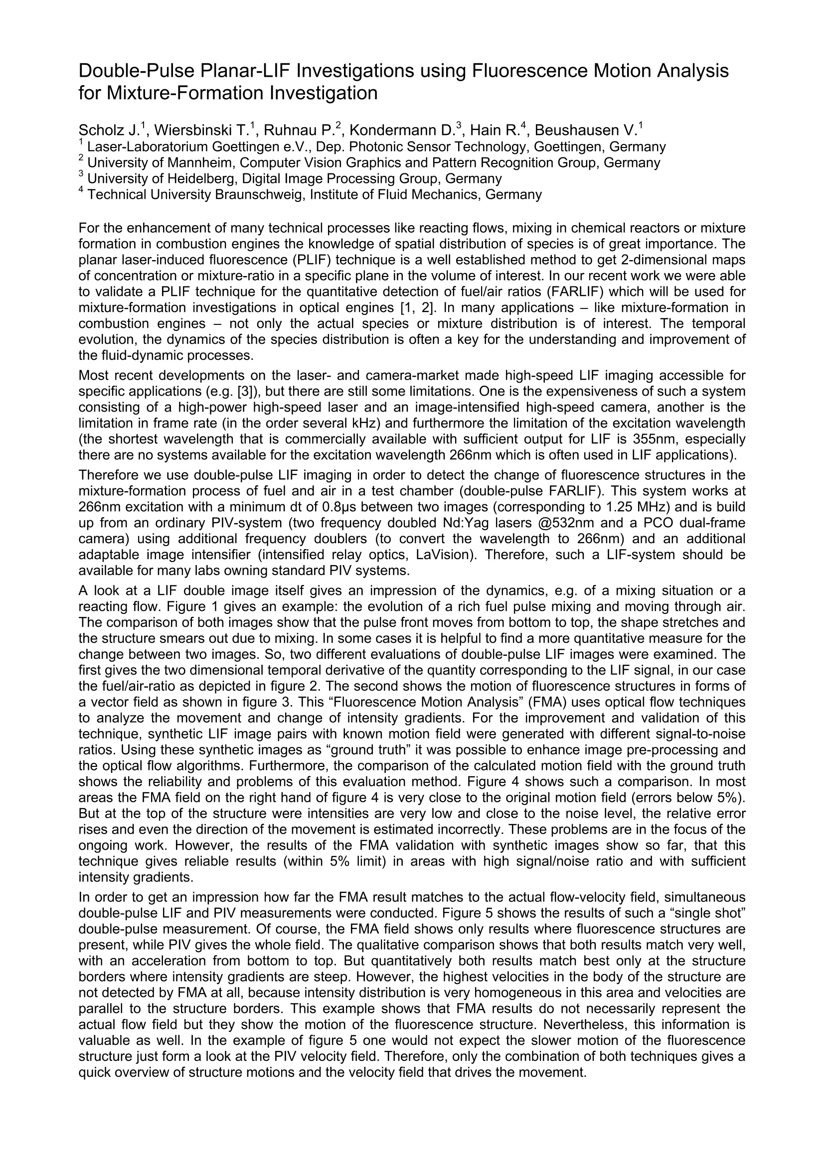
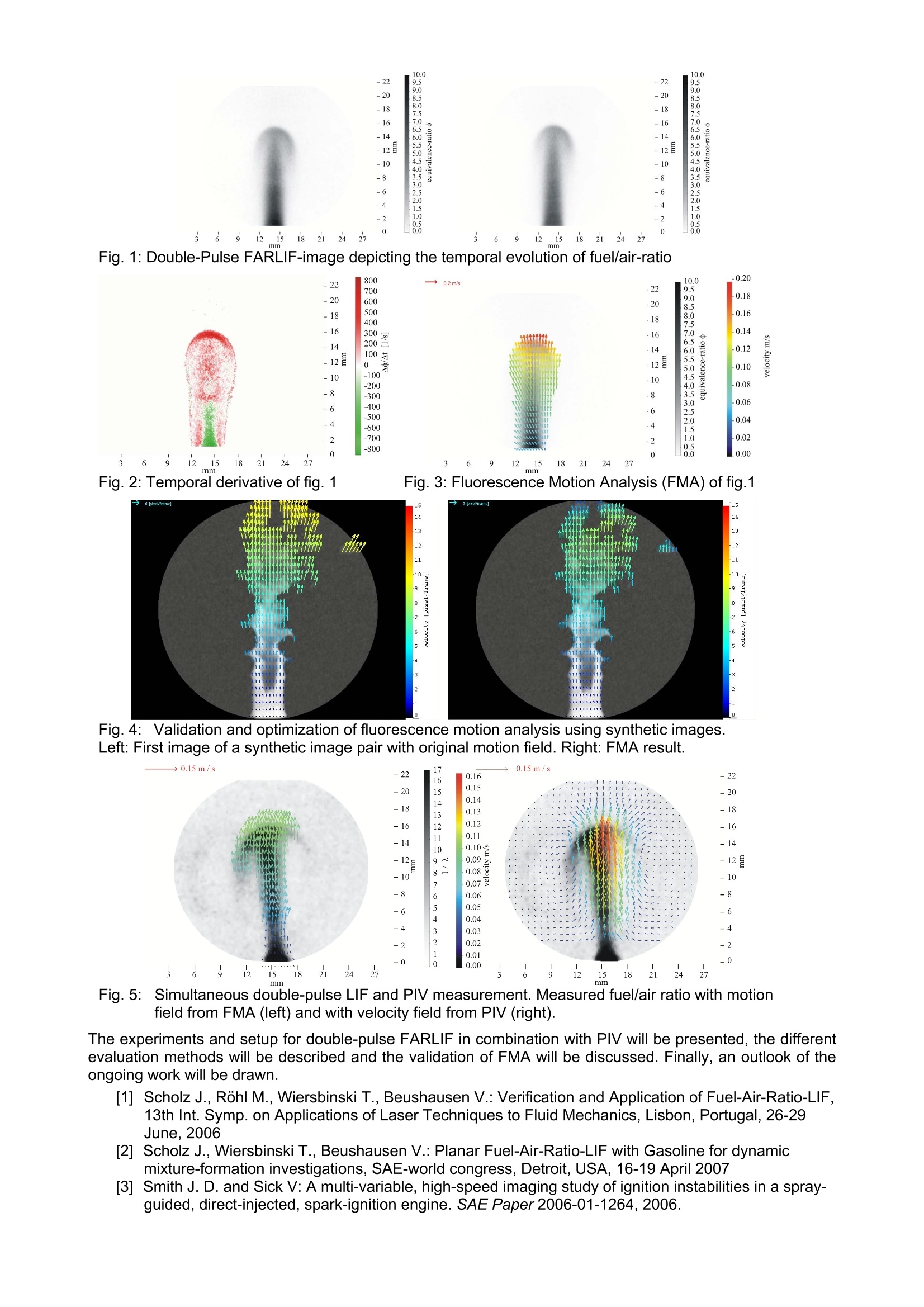
Double-Pulse Planar-LIF Investigations using Fluorescence Motion Analysisfor Mixture-Formation Investigation Scholz J.1, Wiersbinski T.1, Ruhnau P.2, Kondermann D., Hain R., Beushausen V. Laser-Laboratorium Goettingen e.V., Dep. Photonic Sensor Technology, Goettingen, GermanyUniversity of Mannheim, Computer Vision Graphics and Pattern Recognition Group, GermanyUniversity of Heidelberg, Digital Image Proc4essing Group, Germany Technical University Braunschweig, Institute of Fluid Mechanics, Germany For the enhancement of many technical processes like reacting flows, mixing in chemical reactors or mixtureformation in combustion engines the knowledge of spatial distribution of species is of great importance. Theplanar laser-induced fluorescence (PLIF) technique is a well established method to get 2-dimensional mapsof concentration or mixture-ratio in a specific plane in the volume of interest. In our recent work we were ableto validate a PLIF technique for the quantitative detection of fuel/air ratios (FARLIF) which will be used formixture-formation investigations in optical engines [1, 2]. In many applications - like mixture-formation incombustion engines- not only the actual species or mixture distribution is of interest. The temporalevolution, the dynamics of the species distribution is often a key for the understanding and improvement ofthe fluid-dynamic processes. Most recent developments on the laser- and camera-market made high-speed LIF imaging accessible forspecific applications (e.g.[3]), but there are still some limitations. One is the expensiveness of such a systemconsisting of a high-power high-speed laser and an image-intensified high-speed camera, another is thelimitation in frame rate (in the order several kHz) and furthermore the limitation of the excitation wavelength(the shortest wavelength that is commercially available with sufficient output for LIF is 355nm, especiallythere are no systems available for the excitation wavelength 266nm which is often used in LIF applications). Therefore we use double-pulse LIF imaging in order to detect the change of fluorescence structures in themixture-formation process of fuel and air in a test chamber (double-pulse FARLIF). This system works at266nm excitation with a minimum dt of 0.8us between two images (corresponding to 1.25 MHz) and is buildup from an ordinary PIV-system (two frequency doubled Nd:Yag lasers @532nm and a PCO dual-framecamera) using additional frequency doublers (to convert the wavelength to 266nm) and an additionaladaptable image intensifier (intensified relay optics, LaVision). Therefore, such a LIF-system should beavailable for many labs owning standard PIV systems. A look at a LIF double image itself gives an impression of the dynamics, e.g. of a mixing situation or areacting flow. Figure 1 gives an example: the evolution of a rich fuel pulse mixing and moving through air.The comparison of both images show that the pulse front moves from bottom to top, the shape stretches andthe structure smears out due to mixing.In some cases it is helpful to find a more quantitative measure for thechange between two images. So, two different evaluations of double-pulse LIF images were examined. Thefirst gives the two dimensional temporal derivative of the quantity corresponding to the LIF signal, in our casethe fuel/air-ratio as depicted in figure 2. The second shows the motion of fluorescence structures in forms ofa vector field as shown in figure 3. This "Fluorescence Motion Analysis”(FMA) uses optical flow techniquesto analyze the movement and change of intensity gradients. For the improvement and validation of thistechnique, synthetic LIF image pairs with known motion field were generated with different signal-to-noiseratios. Using these synthetic images as “ground truth” it was possible to enhance image pre-processing andthe optical flow algorithms. Furthermore, the comparison of the calculated motion field with the ground truthshows the reliability and problems of this evaluation method. Figure 4 shows such a comparison. In mostareas the FMA field on the right hand of figure 4 is very close to the original motion field (errors below 5%).But at the top of the structure were intensities are very low and close to the noise level, the relative errorrises and even the direction of the movement is estimated incorrectly. These problems are in the focus of theongoing work. However, the results of the FMA validation with synthetic images show so far, that thistechnique gives reliable results (within 5% limit) in areas with high signal/noise ratio and with sufficientintensity gradients. ln order to get an impression how far the FMA result matches to the actual flow-velocity field, simultaneousdouble-pulse LIF and PIV measurements were conducted. Figure 5 shows the results of such a“single shot"double-pulse measurement. Of course, the FMA field shows only results where fluorescence structures arepresent, while PIV gives the whole field. The qualitative comparison shows that both results match very well,with an acceleration from bottom to top. But quantitatively both results match best only at the structureborders where intensity gradients are steep. However, the highest velocities in the body of the structure arenot detected by FMA at all, because intensity distribution is very homogeneous in this area and velocities areparallel to the structure borders. This example shows that FMA results do not necessarily represent theactual flow field but they show the motion of the fluorescence structure. Nevertheless, this information isvaluable as well. In the example of figure 5 one would not expect the slower motion of the fluorescencestructure just form a look at the PIV velocity field. Therefore, only the combination of both techniques gives aquick overview of structure motions and the velocity field that drives the movement. Fig. 1: Double-Pulse FARLIF-image depicting the temporal evolution of fuel/air-ratio mr mm Fig.: Temporal derivative of fig. 1 Fig. 3: Fluorescence Motion Analysis (FMA) of fig. 1 Fig.4: Validation and optimization of fluorescence motion analysis using synthetic images.Left: First image of a synthetic image pair with original motion field. Right: FMA result. 17 -22 16 0.16 -20 15 0.15 0.14 -18 14 13 0.13 -16 12 0.12 -14 11 0.11 10 0.10 125 9 0.09 - 0.08 -10 7 0.07 -8 6 0.06 5 0.05 -6 4 0.04 -4 3 0.03 -2 2 0.02 0.01 3 27 0.00 mm Fig.5:Simultaneous double-pulse LIF and PIV measurement. Measured fuel/air ratio with motionfield from FMA (left) and with velocity field from PIV (right). The experiments and setup for double-pulse FARLIF in combination with PIV will be presented, the differentevaluation methods will be described and the validation of FMA will be discussed. Finally, an outlook of theongoing work will be drawn. [1] Scholz J., Rohl M., Wiersbinski T., Beushausen V.: Verification and Application of Fuel-Air-Ratio-LIF,13th Int. Symp. on Applications of Laser Techniques to Fluid Mechanics, Lisbon, Portugal, 26-29June, 2006 [2] Scholz J., Wiersbinski T., Beushausen V.: Planar Fuel-Air-Ratio-LIF with Gasoline for dynamicmixture-formation investigations, SAE-world congress, Detroit, USA, 16-19 April 2007 [3] Smith J. D. and Sick V: A multi-variable, high-speed imaging study of ignition instabilities in a spray-guided, direct-injected, spark-ignition engine. SAE Paper2006-01-1264,2006.
确定
还剩1页未读,是否继续阅读?

产品配置单


北京欧兰科技发展有限公司为您提供《气体,液体,流体中PLIF,激光诱导荧光,浓度场,混合度,速出场检测方案(流量计)》,该方案主要用于其他中PLIF,激光诱导荧光,浓度场,混合度,速出场检测,参考标准--,《气体,液体,流体中PLIF,激光诱导荧光,浓度场,混合度,速出场检测方案(流量计)》用到的仪器有PLIF平面激光诱导荧光火焰燃烧检测系统、德国LaVision PIV/PLIF粒子成像测速场仪
推荐专场


相关方案
更多
该厂商其他方案
更多