


方案详情
文
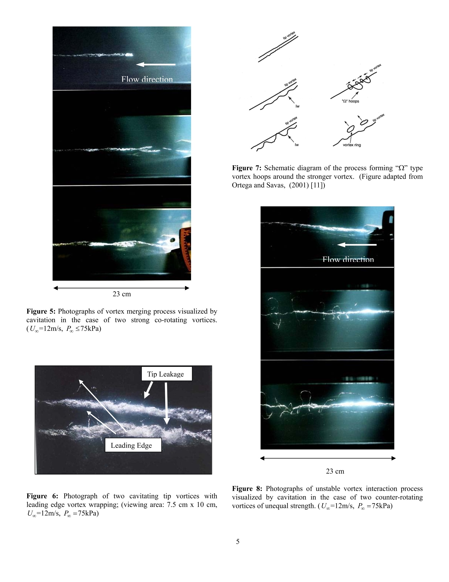
Multiple concentrated vortices are often produced in the wake of lifting surfaces and downstream of pumps, turbines, and propulsors. The roll-up of multiple vortex strands is a common feature of these flows. In this study, we are examining the interaction of two vortices of variable strength and relative rotation (e.g. co-rotating or counter-rotating). A pair of equal-strength co-rotating vortices will merge to form a single vortex. However, as the relative strength of the vortices is decreased, the weaker vortex can wrap around the stronger vortex, causing the weaker vortex to be stretched. This stretching process can lead to cavitation inception. In the present work, we will examine this inception process.
方案详情

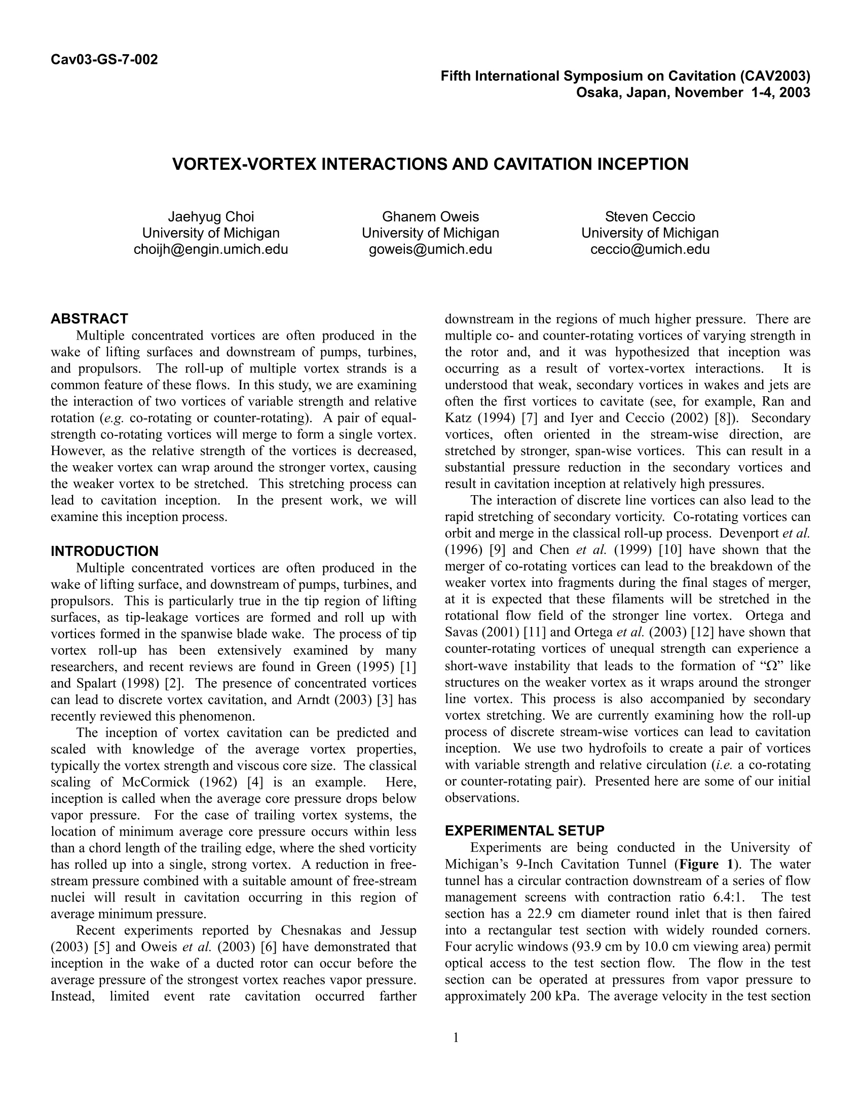
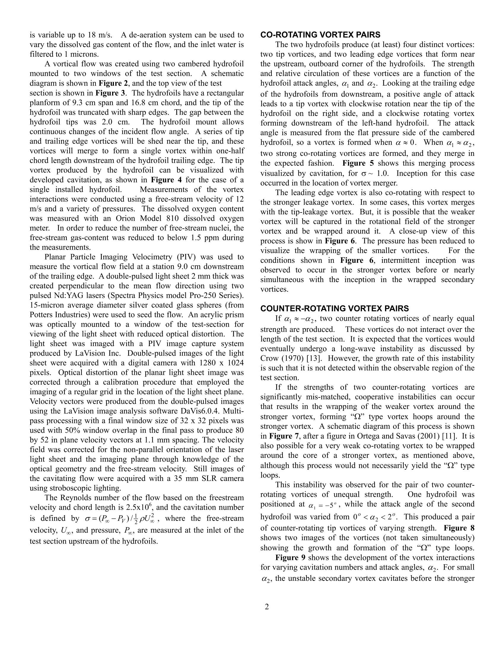
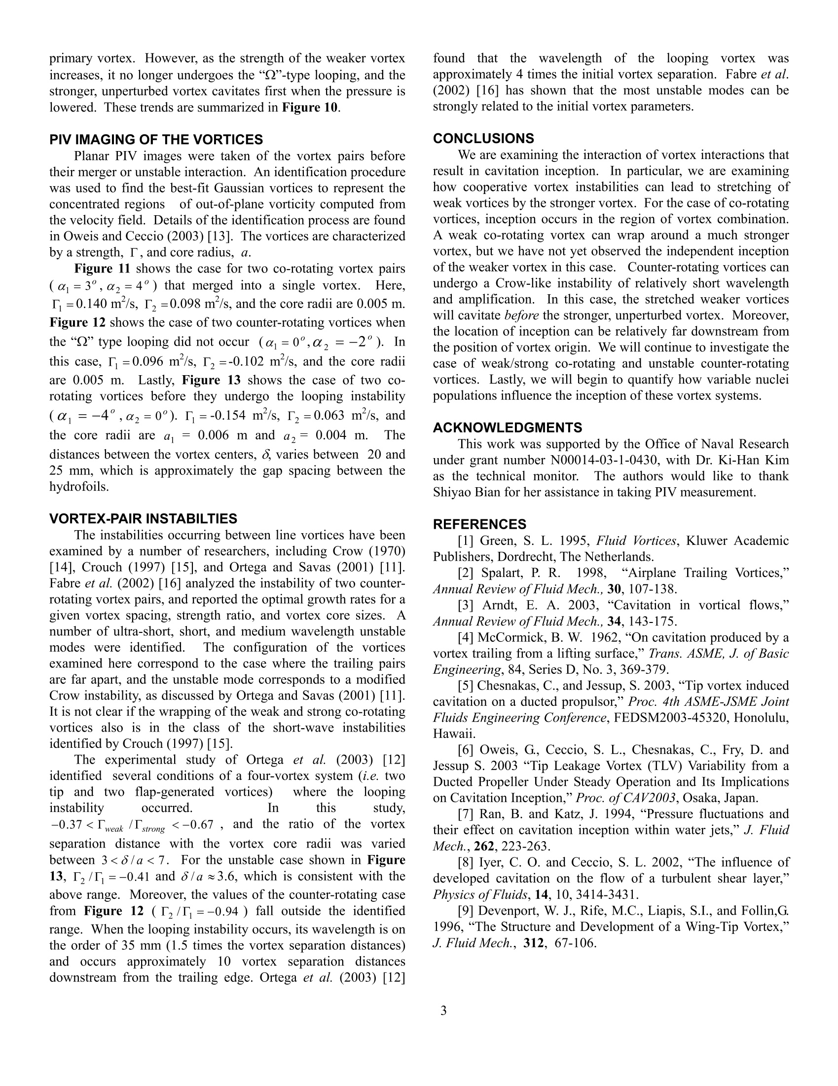
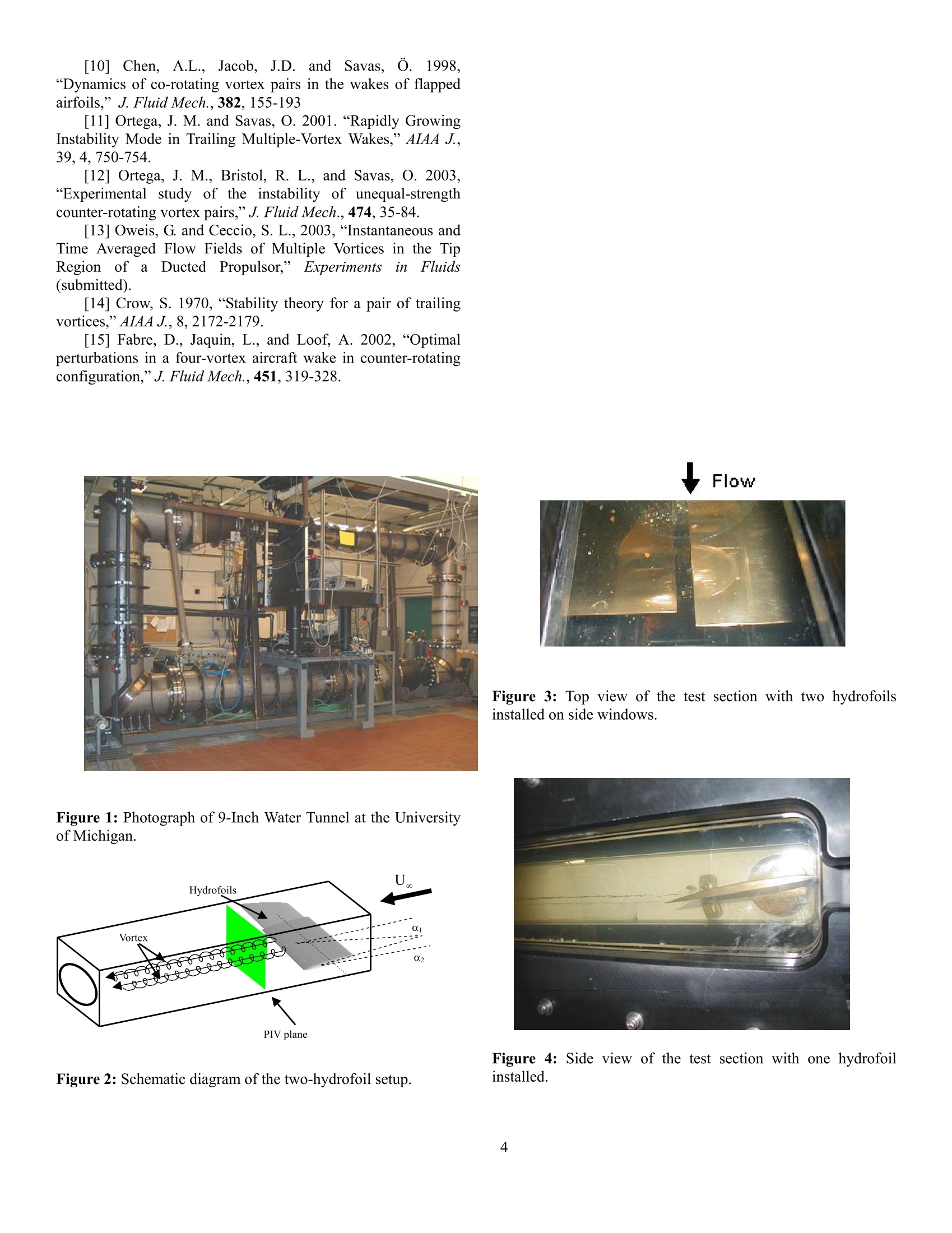
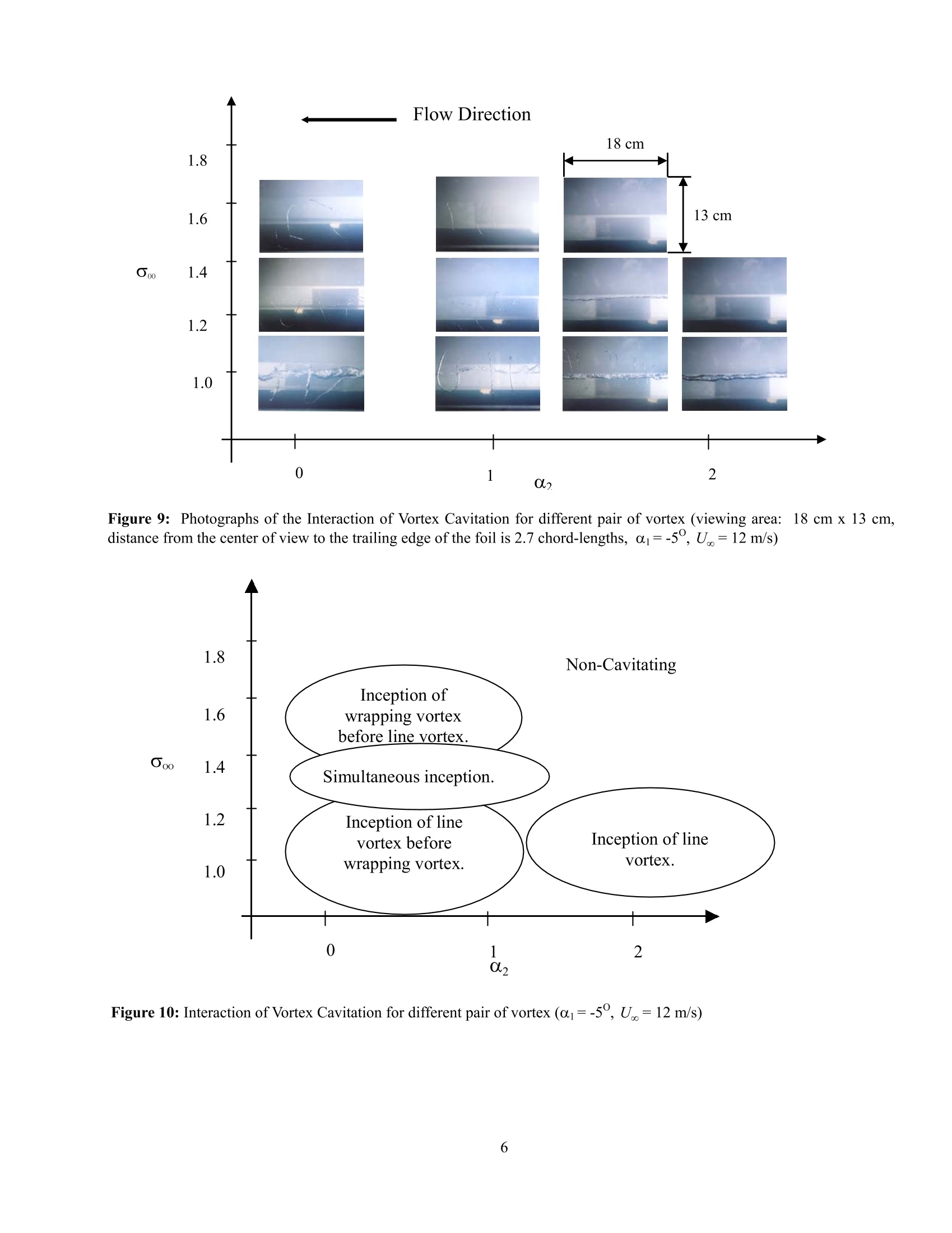
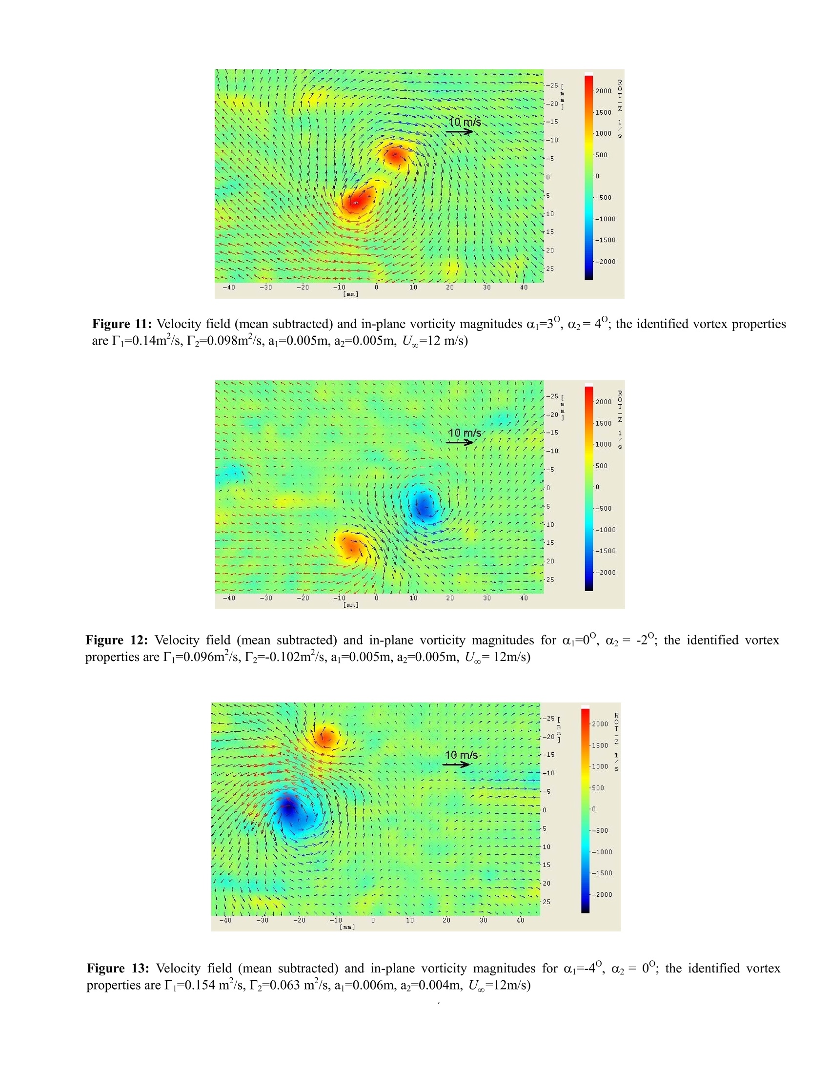
Cav03-GS-7-002Fifth International Symposium on Cavitation (CAV2003)Osaka, Japan, November 1-4,2003 VORTEX-VORTEX INTERACTIONS AND CAVITATION INCEPTION Jaehyug ChoiUniversity of Michiganchoijh@engin.umich.edu Ghanem OweisUniversity of Michigan Steven CeccioUniversity of Michigan goweis@umich.edu ceccio@umich.edu ABSTRACT Multiple concentrated vortices are often produced in thewake of lifting surfaces and downstream of pumps, turbines,and propulsors. The roll-up of multiple vortex strands is acommon feature of these flows. In this study, we are examiningthe interaction of two vortices of variable strength and relativerotation (e.g. co-rotating or counter-rotating). A pair of equal-strength co-rotating vortices will merge to form a single vortex.However, as the relative strength of the vortices is decreased,the weaker vortex can wrap around the stronger vortex, causingthe weaker vortex to be stretched.This stretching process canlead to cavitation inception.1.In the present work, we willexamine this inception process. INTRODUCTION Multiple concentrated vortices are often produced in thewake of lifting surface, and downstream of pumps, turbines, andpropulsors.This is particularly true in the tip region of liftingsurfaces, as tip-leakage vortices are formed and roll up withvortices formed in the spanwise blade wake. The process of tipvortex roll-up lhasbeen extensively examined11by manyresearchers, and recent reviews are found in Green (1995) [1]and Spalart (1998) [2]. The presence of concentrated vorticescan lead to discrete vortex cavitation, and Arndt (2003) [3] hasrecently reviewed this phenomenon. The inception of vortex cavitation can be predicted andscaled with knowledge of thee average vortex properties,typically the vortex strength and viscous core size. The classicalscaling of McCormick (1962) [4] isis an example.. IHere.inception is called when the average core pressure drops belowvapor pressure..For the case of trailing vortex systems, thelocation of minimum average core pressure occurs within lessthan a chord length of the trailing edge, where the shed vorticityhas rolled up into a single, strong vortex. A reduction in free-stream pressure combined with a suitable amount of free-streamnuclei will result in cavitation occurring in this region ofaverage minimum pressure. Recent experiments reported by Chesnakas and Jessup(2003) [5] and Oweis et al. (2003) [6] have demonstrated thatinception in the wake of a ducted rotor can occur before theaverage pressure of the strongest vortex reaches vapor pressure.Instead.,limitedeevent rate cavitation occurred farther downstream in the regions of much higher pressure. There aremultiple co- and counter-rotating vortices of varying strength inthe rotor and, and it was hypothesized that inception wasoccurring asiaa result of vortex-vortex interactions. lt isunderstood that weak, secondary vortices in wakes and jets areoften the first vortices to cavitate (see, for example, Ran andKatz (1994) [7] and Iyer and Ceccio (2002)[8]). Secondaryvortices, often oriented in the stream-wise direction, arestretched by stronger, span-wise vortices. This can result in asubstantial pressure reduction in the secondary vortices andresult in cavitation inception at relatively high pressures. The interaction of discrete line vortices can also lead to therapid stretching of secondary vorticity. Co-rotating vortices canorbit and merge in the classical roll-up process. Devenport et al.(1996) [9] and Chen et al. (1999) [10] have shown that themerger of co-rotating vortices can lead to the breakdown of theweaker vortex into fragments during the final stages of merger,at it is expected that these filaments will be stretched in therotational flow field of the stronger line vortex. Ortega andSavas (2001) [11] and Ortega et al. (2003) [12] have shown thatcounter-rotating vortices of unequal strength can experience ashort-wave instability that leads to the formation of“Q”likestructures on the weaker vortex as it wraps around the strongerline vortex. This process is also accompanied by secondaryvortex stretching. We are currently examining how the roll-upprocess of discrete stream-wise vortices can lead to cavitationinception. We use two hydrofoils to create a pair of vorticeswith variable strength and relative circulation (i.e. a co-rotatingor counter-rotating pair). Presented here are some of our initialobservations. EXPERIMENTAL SETUP Experiments are being conducted in the University ofMichigan’s 9-Inch Cavitation Tunnel (Figure 1). The watertunnel has a circular contraction downstream of a series of flowmanagement screens with contraction ratio 6.4:1. The testsection has a 22.9 cm diameter round inlet that is then fairedinto a rectangular test section with widely rounded corners.Four acrylic windows (93.9 cm by 10.0 cm viewing area) permitoptical access to the test section flow.v.The flow in the testsection can be operated at pressures from vapor pressure toapproximately 200 kPa. The average velocity in the test section is variable up to 18 m/s. A de-aeration system can be used tovary the dissolved gas content of the flow, and the inlet water isfiltered to 1 microns. A vortical flow was created using two cambered hydrofoil mounted to two windows of the test section.A schematicdiagram is shown in Figure 2, and the top view of the testsection is shown in Figure 3. The hydrofoils have a rectangularplanform of 9.3 cm span and 16.8 cm chord, and the tip of thehydrofoil was truncated with sharp edges. The gap between thehydrofoil tips was2.0 cm. The hydrofoil mount allowscontinuous changes of the incident flow angle. A series of tipand trailing edge vortices will be shed near the tip, and thesevortices will merge to form a single vortex within one-halfchord length downstream of the hydrofoil trailing edge. The tipvortex produced by the hydrofoil canbe visualized withdeveloped cavitation, as shown in Figure 4 for the case of asingle installed hydrofoil. Measurements of the vortexinteractions were conducted using a free-stream velocity of 12m/s and a variety of pressures. The dissolved oxygen contentwas measured with an Orion Model 810 dissolved oxygenmeter.In order to reduce the number of free-stream nuclei, thefree-stream gas-content was reduced to below 1.5 ppm duringthe measurements. Planar Particle Imaging Velocimetry (PIV) was used tomeasure the vortical flow field at a station 9.0 cm downstreamof the trailing edge. A double-pulsed light sheet 2 mm thick wascreated perpendicular to the mean flow direction using twopulsed Nd:YAG lasers (Spectra Physics model Pro-250 Series).15-micron average diameter silver coated glass spheres (fromPotters Industries) were used to seed the flow. An acrylic prismwas optically mounted to a window of the test-section forviewing of the light sheet with reduced optical distortion. Thelight sheet was imaged with a PIV image capture systemproduced by LaVision Inc. Double-pulsed images of the lightsheet were acquired with a digital camera with 1280 x 1024pixels. Optical distortion of the planar light sheet image wascorrected through a calibration procedure that employed theimaging of a regular grid in the location of the light sheet plane.Velocity vectors were produced from the double-pulsed imagesusing the LaVision image analysis software DaVis6.0.4. Multi-pass processing with a final window size of 32 x 32 pixels wasused with 50% window overlap in the final pass to produce 80by 52 in plane velocity vectors at 1.1 mm spacing. The velocityfield was corrected for the non-parallel orientation of the laserlight sheet and the imaging plane through knowledge of theoptical geometry and the free-stream velocity. Still images ofthe cavitating flow were acquired with a 35 mm SLR camerausing stroboscopic lighting. The Reynolds number of the flow based on the freestreamvelocity and chord length is 2.5x10°, and the cavitation numberis defined by =(P-P)/,pU, where the free-streamvelocity, U., and pressure, Po, are measured at the inlet of thetest section upstream ofthe hydrofoils. CO-ROTATING VORTEX PAIRS The two hydrofoils produce (at least) four distinct vortices:two tip vortices, and two leading edge vortices that form nearthe upstream, outboard corner of the hydrofoils..The strengthand relative circulation of these vortices are a function of thehydrofoil attack angles, a and a. Looking at the trailing edgeof the hydrofoils from downstream, a positive angle of attackleads to a tip vortex with clockwise rotation near the tip of thehydrofoil on the right side, and a clockwise rotating vortexforming downstream of the left-hand hydrofoil.. The attackangle is measured from the flat pressure side of the camberedhydrofoil, so a vortex is formed when a~ 0. When a ~ a2,two strong co-rotating vortices are formed, and they merge inthe expected fashion. Figure 5 shows this merging processvisualized by cavitation, for o~ 1.0. Inception for this caseoccurred in the location of vortex merger. The leading edge vortex is also co-rotating with respect tothe stronger leakage vortex. In some cases, this vortex mergeswith the tip-leakage vortex. But, it is possible that the weakervortex will be captured in the rotational field of the strongervortex and be wrapped around it.A close-up view of thisprocess is show in Figure 6. The pressure has been reduced tovisualize the wrapping of the smaller vortices. For theconditions shown in Figure 6, intermittent inception wasobserved to occur in the stronger vortex before or nearlysimultaneous with the inception in the wrapped secondaryvortices. COUNTER-ROTATING VORTEX PAIRS If a~-a2, two counter rotating vortices of nearly equalstrength are produced. These vortices do not interact over thelength of the test section. It is expected that the vortices wouldeventually undergo a long-wave instability as discussed byCrow (1970) [13]. However, the growth rate of this instabilityis such that it is not detected within the observable region of thetest section. If the strengths of two counter-rotating vorticesaresignificantly mis-matched, cooperative instabilities can occurthat results in the wrapping of the weaker vortex around thestronger vortex, forming“Q”type vortex hoops around thestronger vortex. A schematic diagram of this process is shownin Figure 7, after a figure in Ortega and Savas (2001)[11]. It isalso possible for a very weak co-rotating vortex to be wrappedaround the core of a stronger vortex, as mentioned above,although this process would not necessarily yield the“Q”typeloops. This instability was observed for the pair of two counter-rotating vortices of unequal strength. One hydrofoil waspositioned at a=-5°, while the attack angle of the secondhydrofoil was varied from 0°2<2°. This produced a pairof counter-rotating tip vortices of varying strength. Figure 8shows two images of the vortices (not taken simultaneously)showing the growth and formation of the “”type loops. Figure 9 shows the development of the vortex interactionsfor varying cavitation numbers and attack angles, a. For smalla,the unstable secondary vortex cavitates before the stronger primary vortex. However, as the strength of the weaker vortexincreases, it no longer undergoes the “Q"-type looping, and thestronger, unperturbed vortex cavitates first when the pressure islowered. These trends are summarized in Figure 10. PIV IMAGING OF THE VORTICES Planar PIV images were taken of the vortex pairs beforetheir merger or unstable interaction. An identification procedurewas used to find the best-fit Gaussian vortices to represent theconcentrated regions of out-of-plane vorticity computed fromthe velocity field. Details of the identification process are foundin Oweis and Ceccio (2003)[13]. The vortices are characterizedby a strength, T, and core radius, a. Figure 11 shows the case for two co-rotating vortex pairs(c=3,az=4°) that merged into a single vortex.Here.r=0.140 m²/s,Tz=0.098 m’/s, and the core radii are 0.005 m.Figure 12 shows the case of two counter-rotating vortices whenthe “Q”type looping did not occur (a=0°,a2=-2). Inthis case, T=0.096 m /s, Iz=-0.102 m /s, and the core radiiare 0.005 m.Lastly, Figure 13 shows the case of two co-rotating vortices before they undergo the looping instability(a=-4°,2=0°).I=-0.154 m /s,Tz=0.063 m /s, andthe core radii are a=0.006 m and a2= 0.004 m. Thedistances between the vortex centers, 8,varies between 20 and25 mm, which is approximately the gap spacing between thehydrofoils. VORTEX-PAIR INSTABILTIES The instabilities occurring between line vortices have beenexamined by a number of researchers, including Crow (1970)[14], Crouch (1997) [15], and Ortega and Savas (2001) [11].Fabre et al. (2002) [16] analyzed the instability of two counter-rotating vortex pairs, and reported the optimal growth rates for agiven vortex spacing, strength ratio, and vortex core sizes.5.Anumber of ultra-short, short, and medium wavelength unstablemodes were identified. The configuration of the vorticesexamined here correspond to the case where the trailing pairsare far apart, and the unstable mode corresponds to a modifiedCrow instability, as discussed by Ortega and Savas (2001) [11].It is not clear if the wrapping of the weak and strong co-rotatingvortices also is in the class of the short-wave instabilitiesidentified by Crouch (1997) [15].l. The experimental study of Ortega et al. (2003)) 12|identifiedi:several conditions of a four-vortex system (i.e. twop and twoflap-generatedvortices) where the loopinginstability occurred. In this study,-0.37
确定
还剩5页未读,是否继续阅读?

产品配置单

北京欧兰科技发展有限公司为您提供《漩涡,空穴中漩涡间相互作用,空穴生成机理,速度场,速度矢量场,流场检测方案(粒子图像测速)》,该方案主要用于其他中漩涡间相互作用,空穴生成机理,速度场,速度矢量场,流场检测,参考标准--,《漩涡,空穴中漩涡间相互作用,空穴生成机理,速度场,速度矢量场,流场检测方案(粒子图像测速)》用到的仪器有德国LaVision PIV/PLIF粒子成像测速场仪、Imager SX PIV相机
推荐专场


相关方案
更多
该厂商其他方案
更多