


方案详情
文
This work presents preliminary results of flow separation control from the flap of a
high-lift airfoil using a single dielectric barrier discharge (DBD) plasma actuator. Control
effectiveness is investigated for two actuator locations as well as various reduced frequencies,
applied voltages and waveforms. Results show that a single DBD plasma actuator located at
the flap shoulder can slightly increase or reduce the size of the time-averaged separation
bubble over the flap depending on the frequency of actuation. This effectiveness is not
improved by an increase in applied voltage or a change from a sinusoidal to positive
sawtooth waveform for the cases examined. Spatial eigenmodes calculated from twocomponent
PIV using POD show that a single DBD plasma actuator at the flap shoulder can
have a significant effect on the structure of higher order modes. However the corresponding
energy of these modes is low in comparison to the dominant modes in the wake.
Nomenclature
Cp =
方案详情

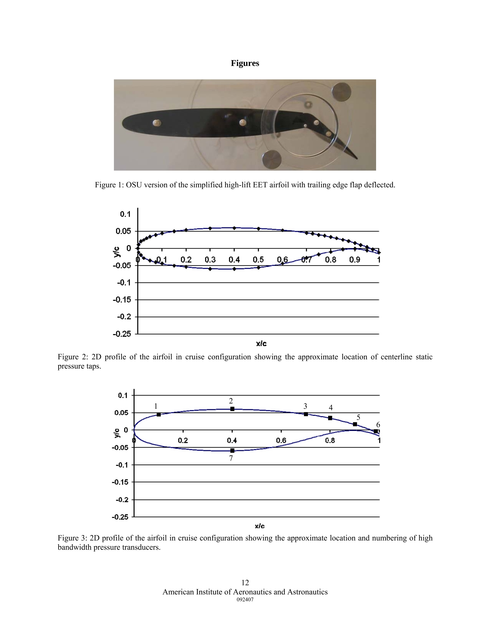
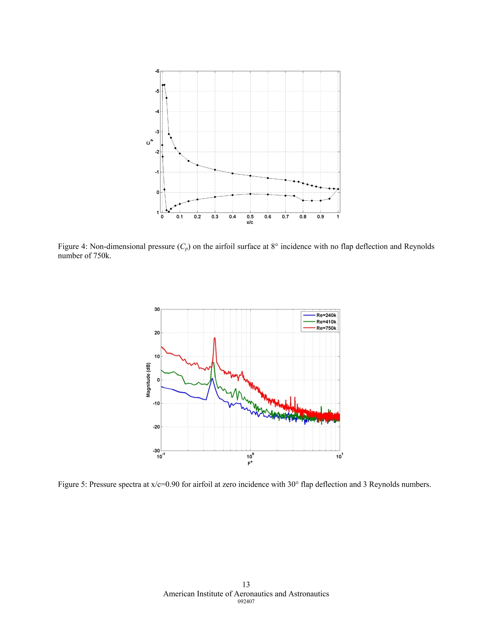
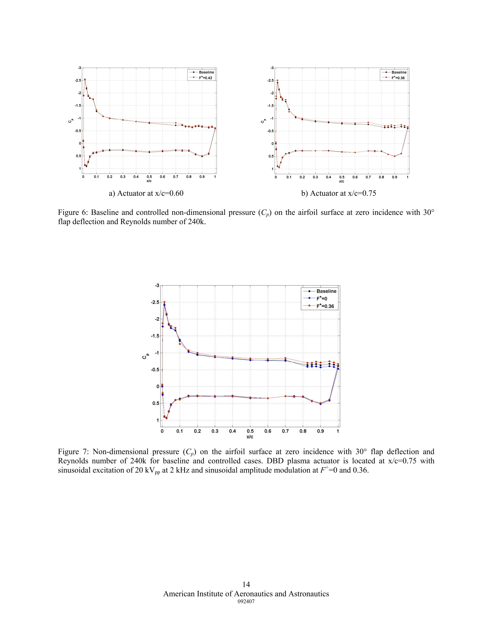
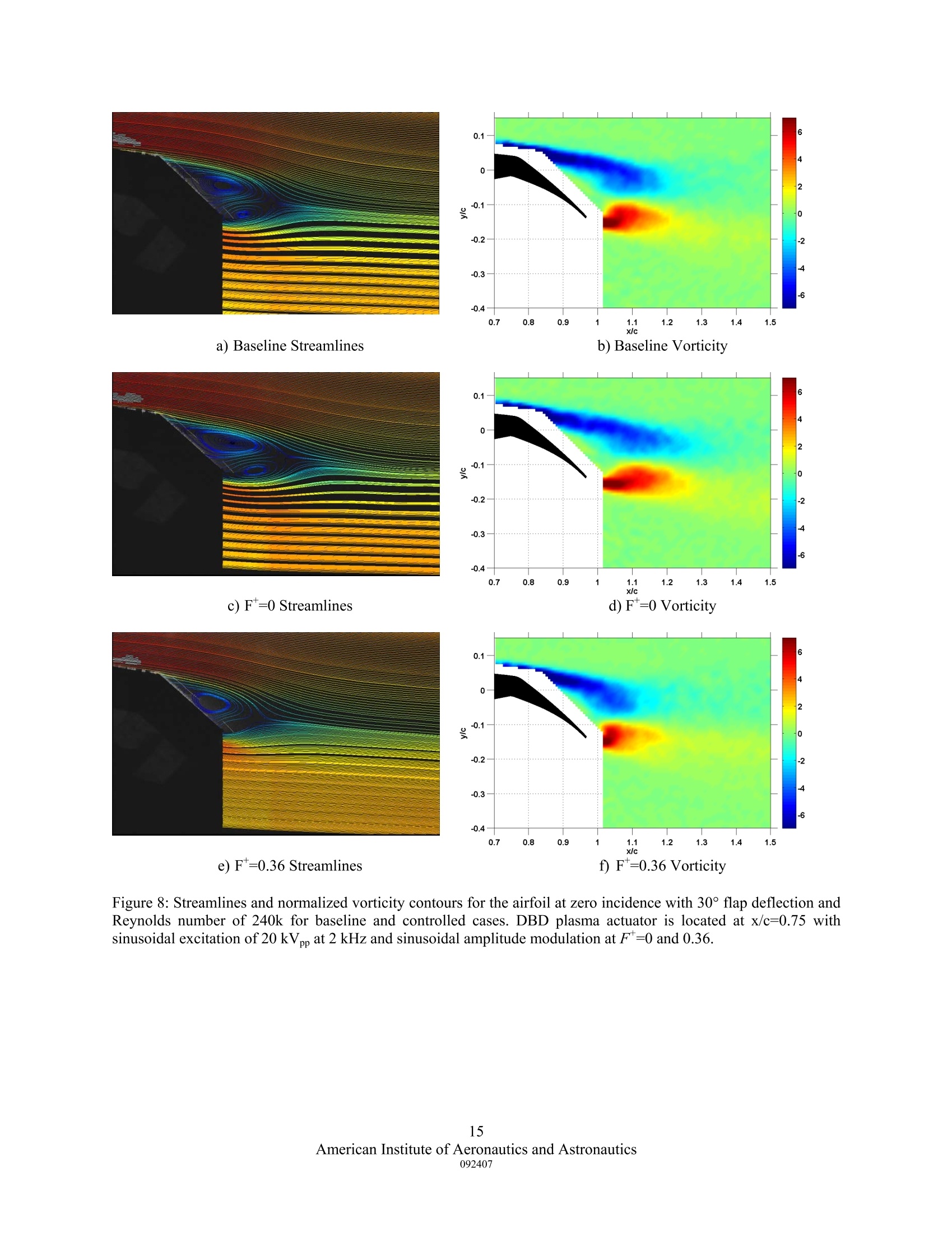
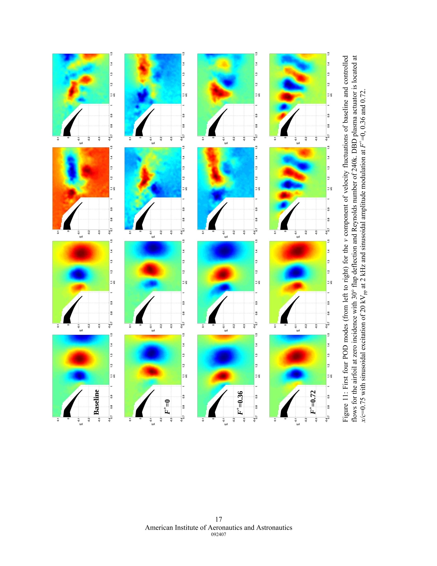
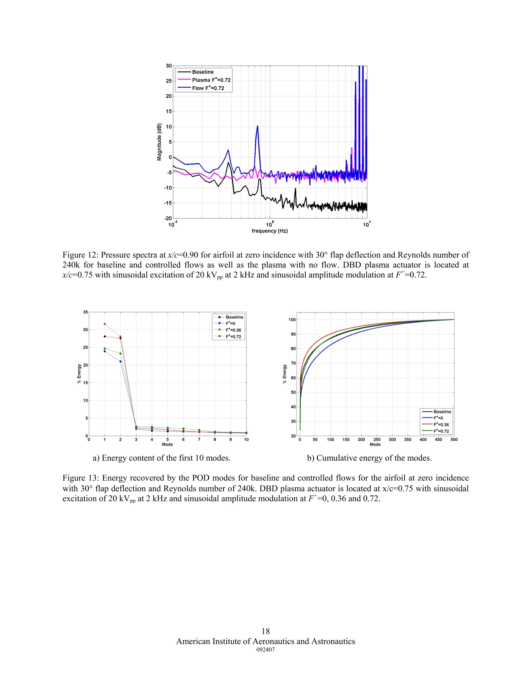
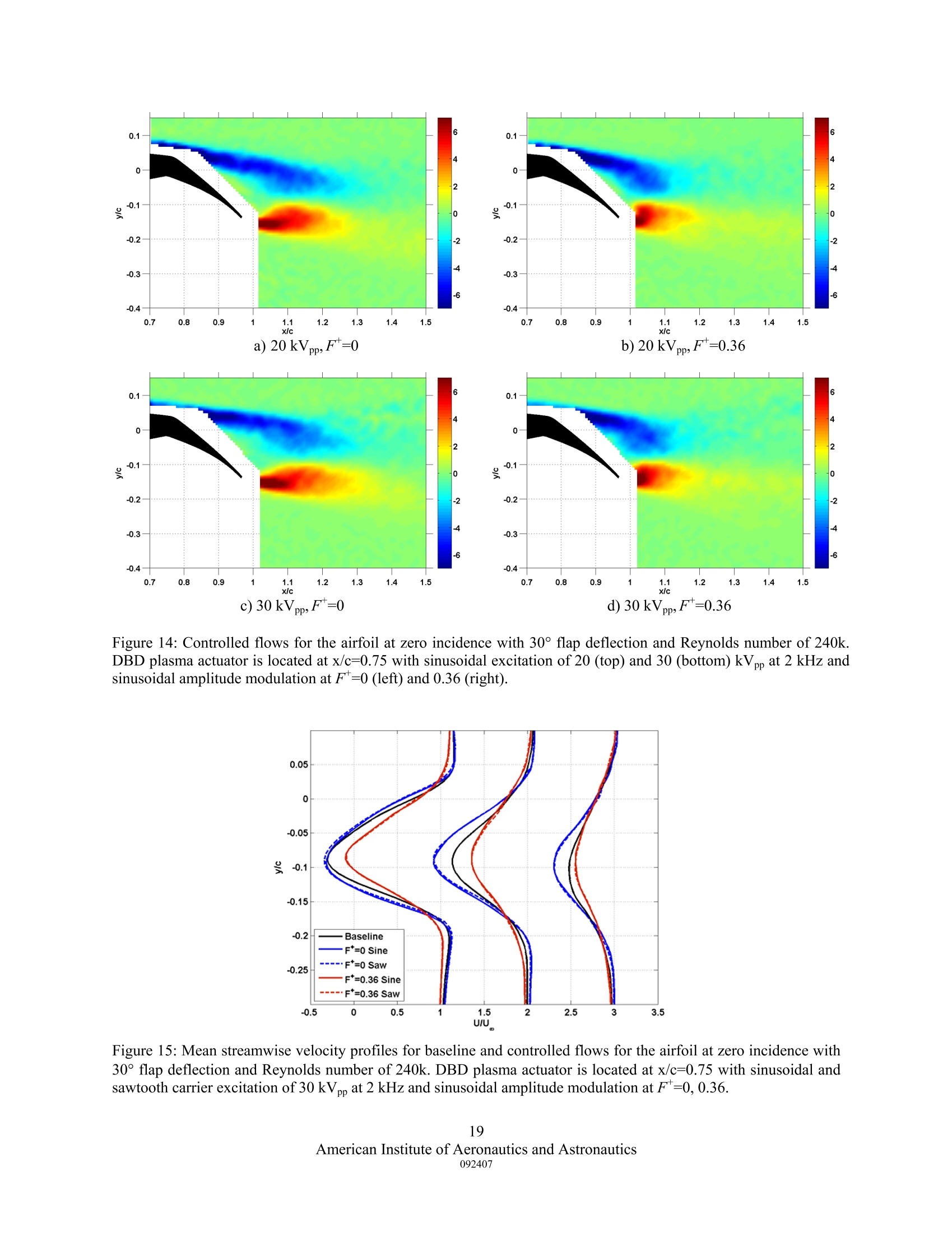
Separation Control from the Flap of a High-Lift Airfoilusing DBD Plasma Actuation Jesse Little, Munetake Nishiharal, Igor Adamovich and Mo Samimy Gas Dynamics and Turbulence Laboratory The Ohio State University, Department of Mechanical Engineering, Columbus, OH This work presents preliminary results of flow separation control from the flap of ahigh-lift airfoil using a single dielectric barrier discharge (DBD) plasma actuator. Controleffectiveness is investigated for two actuator locations as well as various reduced frequencies,applied voltages and waveforms. Results show that a single DBD plasma actuator located atthe flap shoulder can slightly increase or reduce the size of the time-averaged separationbubble over the flap depending on the frequency of actuation. This effectiveness is notimproved by an increase in applied voltage or a change from a sinusoidal to positivesawtooth waveform for the cases examined. Spatial eigenmodes calculated from two-component PIV using POD show that a single DBD plasma actuator at the flap shoulder canhave a significant effect on the structure of higher order modes. However the correspondingenergy of these modes is low in comparison to the dominant modes in the wake. Nomenclature pressure coefficientcf k airfoil model chord frequency =rreduced frequency wind tunnel calibration constant pstatic pressureRUUv stagnation pressure ffreestream dynamic pressure = cchord-based Reynolds number =streamwise velocity freestream velocity vvertical fluctuating velocity length of separated region x/c =rnormalized streamwise coordinate y/c = normalized vertical coordinate ( G raduate Research Associate, AIAA Student Member. ) ( ' Post-Doctoral Researcher,AIAA Member. ) ( + Associate Professor, AIAA Associate Fellow. ) ( T h e Howard D. Winbigler Professor of Engineering, AIAA Associate F e llow, Corresponding Author. ) I. Introduction Aerodynamic flow control is a broad discipline encompassing the fields of fluid mechanics, actuatordesign, feedback control and more recently plasma physics. The successful implementation of aerodynamic flowcontrol has applications in structural fatigue, aircraft maneuverability, noise mitigation and overall flight efficiency.In particular, control of flow separation is an active area of research due to the prevalence of this phenomenon inaerodynamic applications such as turbomachinary, diffusers and airfoils. The last application is the focus of thiswork. High-lift airfoils typically employ trailing edge flaps that can be deflected during take-off or landing andstowed during cruise. Such devices enhance the lift curve of conventional airfoils, but can impose a penalty due toflow separation that occurs when the momentum of fluid in the boundary layer is not sufficient to overcome the wallfriction and adverse pressure gradient encountered as it travels over an aerodynamic surface. In this situation, theflow separates which can result in a stalled condition characterized by an abrupt decrease in lift and an increase inpressure drag. Traditional methods of eliminating flow separation over these devices use multi-element flaps toallow mixing of fluid between the pressure and suction sides. These systems, while effective, create significantincreases in mechanical complexity and weight of the aircraft. In addition, the external hinges and positioningactuators required for such devices generate parasitic drag when stowed in the cruise configuration. The replacementof conventional multi-element flap systems with a simple flap utilizing active flow control technology is a viablealternative if the necessary performance criteria can be enhanced or at least maintained. Active separation controlwith respect to high-lift applications has additional appeal due the expanding need for transport aircraft withcapability for Super and Extreme Short Take-Off and Landing (SSTOL & XSTOL). Control of flow separation over simple flaps on high-lift airfoils has been recently investigated in bothopen-loop (Kiedaisch et al. 2006, Melton et al. 2006a) and closed-loop (Becker et al. 2007) configurations usingsynthetic jets. These devices are capable of producing strong velocity fluctuations, but are limited to actuation fromspecific locations that must be chosen and integrated into the design of the airfoil model. This places restrictions onthe control effectiveness of such systems due to the variable separation location and corresponding receptivityregion that is inherent for airfoil applications where both incidence and flap deflection angles can vary. DBD plasmaactuators produce induced flows at least an order of magnitude lower than most synthetic jets, but in their simplestlaboratory form (thin adhesive tape) can be located anywhere on the airfoil surface and also allow the flexibility toconform to surface curvature. An additional contrast between synthetic jets and DBD plasma actuators is thatsynthetic jets by nature produce actuation at a specific location whereas DBD plasma actuators create both suctionand a wall jet over a volume in quiescent conditions. These devices also allow the possibility of placing multipleactuators in a various locations and orientations on the airfoil surface. The advantages and disparities of DBD plasma actuators with respect to synthetic jets as well as the varietyof parameters that can be explored (size, location, number, etc.) make them amenable devices for studies of high-liftseparation control in take-off and landing applications in laboratory settings. The development of successfulstrategies for using such actuators coupled with the complexity of flow separation and the possibility of feedbackcontrol makes this a very rich and stimulating problem spanning multiple disciplines. However, the ultimate albeitambitious objective of this work is to achieve high-lift using a single element airfoil employing a simple flap bydesigning and implementing an active separation control system. In order to do so, suitable control and actuationstrategies must be designed by examining the separated flow phenomenon over a range of low incidence angles, flapdeflection angles and Reynolds numbers. It is hoped that the success of this project will further the development of anew generation of military and civil aircraft with integrated active flow control technology. The remaining portions of this paper gives some background information on separation control in high-liftapplications with an additional focus on the current state of DBD plasma actuators. This is followed by anexplanation of the experimental facilities and techniques used in this work and some preliminary results of thecontrol effectiveness of a single DBD plasma actuator for reducing airfoil trailing edge separation. II. Background Separation Control Separation control is a widely studied topic and consequently thorough reviews on its various applicationshave been published in the past (Gad-el-Hak and Bushnell 1991, Greenblatt and Wygnanski 2000). Passiveseparation control techniques which generally constitute geometric changes such as vortex generators and slottedflaps/slats are employed on many operational aircraft. These control elements are effective if the aircraft is operatingin a flight regime that is in their design envelope. However, in off-design conditions, passive control elements canhave detrimental effects that are often manifested in the form of increased drag. Despite this drawback,the benefits of passive control techniques often outweigh the incurred cost created by their application to the aerodynamicsurface. Active separation control has gained popularity in recent years due to its potential for maintaining orenhancing the benefits of passive control techniques without the incurred cost associated with operation in off-design conditions. The main difference here being that active control can be turned on and off by command allowingadditional flexibility. Active control strategies also could have the potential to be implemented in a feedback systemthat coupled with adequate sensors and controller could create even greater benefits in flight efficiency andmaneuverability Technological advances over the last 20 years have allowed researchers to more fully explore the wideparameter space associated with this research topic. Accordingly, significant advances in the understanding ofseparated flow phenomena in response to synthetic jet actuation have followed. Among the most widely accepted isthat unsteady actuation via blowing, suction or both is more effective than steady forcing (Seifert et al.1996). Therange of effective non-dimensional frequencies associated with this is on the order of unity (Darabi and Wygnanski2004, Glezer et al. 2005) where the non-dimensional frequency (reduced frequency/Strouhal number), Fis definedas where fis the forcing frequency, xsp is the length of the separated region and U. is the freestream velocity. Thisparameter underscores the importance of the characteristic length scale of separated flow phenomena, xsp, which isthe length of the separation zone over the body in question (Seifert et al. 1996). The importance of actuation locationis closely related to this expression since the shear layer by nature selectively amplifies small perturbations if theyare introduced near its receptivity region. The optimum choice of this location for synthetic jet actuation is generallyat or slightly upstream of the separation point. This ensures that the shear layer is excited by the controlperturbations near its receptivity region. Successful introduction of such forcing creates large spanwise vortices thatencourage momentum transport between the freestream and separated region thus reattaching the flow (Darabi andWygnanski 2004, Melton et al. 2005). Forcing at higher frequencies (F*>10) has been classified as a differentregime and is characterized by enhanced energy dissipation (Amitay and Glezer 2002). Studies on control ofspecifically trailing edge (TE) separation have shown that significantly more momentum input is required incomparison with leading edge (LE) control (Melton et al. 2006a). This is in agreement with LE separation controlstudies that show greater centripetal acceleration created by airfoil surface curvature requires additional momentumfor realizing similar control authority (Greenblatt and Wygnanski 2003). Because of this challenge, it is difficult tofully attach the flow over the TE flap. Consequently, lift gains associated with this are often manifested fromupstream effects such as an increase in overall circulation (Kiedaisch et al. 2006, Melton et al.2006a). Additionalwork has shown that the simultaneous use of multiple actuators distributed along the airfoil chord has been moresuccessful than the contribution from each actuator alone (Greenblatt 2007). Not surprisingly, the relative phase ofsuch actuators is an important parameter that is highly dependent on the spacing between actuators and theexcitation frequency (Greenblatt 2007, Melton et al. 2007). DBD Plasma Actuators The recent interest in plasma actuators for aerodynamic flow control is motivated by their simpleconstruction, fast time response and ease of implementation. Because of these amenable characteristics, significantliterature has been published on this subject to warrant a review (Moreau 2007). While such devices are relativelynew to the aerodynamic community, DBD plasma actuators have long been used in a variety of industrialapplications (Kogelschatz 2003). The DBD plasma actuator is usually composed of 2 electrodes separated by adielectric material. Application of a sufficiently high voltage (5-30 kV) AC (1-10 kHz) signal to the exposedelectrode weakly ionizes the air over the grounded electrode. In quiescent conditions, these charged particles in thepresence of the electric field transfer momentum to the flow creating suction above the anode and a pseudo wall jetover and downstream of the cathode with maximum velocity of 1-7 m/s approximately 1 mm from the wall. Theinduced flow generally increases with applied voltage, but the shape of this relationship is in dispute (Enloe et al.2004b, Forte et al. 2007). Early examples of DBD plasma actuators as flow control devices demonstrated theirpotential for boundary layer and LE airfoil separation control applications (Roth et al. 2000, Post and Corke 2004).More recently, experimental studies using such devices have broadened to include jet mixing, thrust vectoring andcavity tone attenuation (Bernard et al.2007, Bolitho and Jacob 2008, Chan et al. 2007). While these new applications have gained popularity in recent years, the majority of DBD plasma work still relates to separationcontrol. The mechanism responsible for separation control by DBD plasma is most often associated with the suctionand wall jet generation described above, but whether this results in boundary layer tripping or energizing is still indebate and likely depends on the application. Unlike synthetic jets, the exact location at which the plasma actuatoraccomplishes control is not immediately obvious although actuators placed slightly upstream of the separationlocation give favorable results (Huang et al. 2006). An additional complexity is associated when consideringnanosecond pulsed DC plasmas that seem to accomplish control by thermal effects alone (Roupassov et al. 2008). Inany case,DBD plasma actuators, like synthetic jets, are often most effective for separation control whene xonis unsteady with reduced frequency on the order of unity (Huang et al. 2006, Sosa et al. 2007, Greenblatt et al. 2008,Patel et al. 2008). To operate in this fashion, the actuator must be excited with a sufficient carrier frequency toproduce the plasma (1-10 kHz) and amplitude modulated or varied in duty cycle to excite the long wavelengthinstabilities associated with most separated flow dynamics. This behavior is analogous to synthetic jets created bypiezoelectric diaphragms which produce the highest intensity fluctuations when excited near their resonantfrequency which is usually on the order of a few kHz. The success of DBD plasma actuators for boundary layer and separation control has motivated a significantamount of study into the mechanisms associated with control effectiveness. The focus here is generally to maximizethe velocity of the wall jet created by such devices. Enloe et al. (2004b) used a model of the DBD plasma actuator toshow that the highest force density associated with such devices is near the edge of the exposed electrode. Anaccompanying study reported that the plasma characteristics are significantly different in the positive and negativegoing portions of the applied voltage waveform in that the latter produces a much more diffuse plasma. This wasstudied optically for positive and negative sawtooth waveforms and a positive correlation between the uniformity ofthe discharge and the thrust created by the induced flow was found (Enloe et al. 2004a). Using this reasoning, bulkheating was disregarded as a mechanism for momentum coupling into neutral air. Other research has since supportedthis claim (Jukes et al. 2006, Sung et al. 2006). Building on previous research, Forte et al. (2007) produced anextensive parametric study on the optimization of the DBD plasma actuator with respect to the induced flowvelocity. This resulted in maximum average wall jet velocities up to 7 m/sec for a single actuator. Others continue toinvestigate the possibility of producing increased DBD actuator control authority using both modeling andexperiments (Likhanskii et al. 2008, Opaits et al. 2008). However, it has been recently shown that the forceproduction from a DBD plasma actuator decreases with decreasing pressure (Gregory et al. 2007). This puts theapplication of such devices at cruising altitudes in question. Nevertheless, strides continue to be made forimplementation of such devices as they have recently been used with varying degrees of success in feedback controland flight testing (Patel et al. 2007, Sidorenko et al. 2008). III. Experimental Facility and Measurements Techniques Wind Tunnel A Gottingen-type, closed, recirculating wind tunnel with an optically accessible 61 x 61 x 122cm (2x2x4 ft) test section serves as the test bed for this study. Test sections walls are constructed of 25.4 mm (1 in) thicksuper abrasion resistant acrylic. Each side wall is fitted with a 30.5 cm (12 in) diameter port that is located 30.5 cm(12 in) from the test section floor and 61 cm (24 in) downstream ofthe test section entrance. Air flow in the tunnel iscreated by an axial fan powered with a 200 hp AC induction motor. The contraction before the test section has asymmetrical cross section and an area ratio of 6.25:1. The primary diffuser downstream of the test section expandswith a total angle of 6°. This assembly allows continuously variable air velocity in the tunnel from 3-90 m/s (10-300ft/s). Flow conditioning upstream of the test section includes a hexagonal cell aluminum honeycomb while highporosity stainless steel screens are mounted downstream of the test section as a safety catch. Four high efficiencyturning cascades fabricated of galvanized steel are installed in each of the four tunnel elbows. This assembly resultsin freestream turbulence levels on the order of 0.25% with +/-1% variation in mean freestream velocity measured 6inches from the test section inlet. The tunnel is also equipped with a commercial aluminum fin/copper tube, doublerow heat exchanger with set point controller and electronic modulating valve. This arrangement allows the tunnelfreestream operating temperature to be maintained at +/-1 ℃ from the ambient when supplied a sufficient source ofcooling water (max 50 gpm). A 2D traversing assembly driven by DC stepper motors is mounted on top of the testsection allows introduction of instrumentation such as pitot and hot wire probes through a 109 cm (42.8 in) longhigh density nylon brush seal along the tunnel centerline. Overall dimensions of the tunnel discounting thetraversing assembly are 9.8 x 2.2 x 4.1 m’ with a test section centerline height of 1.4 m. A piezometer ring consisting of 4 static pressure taps located on the centerline of each contraction panel isinstalled 50.8 mm (2 in) from both the contraction entrance and exit. Vertical profiles of the dynamic pressure havebeen measured using a pitot probe at streamwise locations of 0, 30.5, 61 and 85 cm (0, 12, 24 and 33.5 in) relative tothe test section entrance for velocities in the range 10-90 m/s with a 10 m/s increment. Note that 85 cm (33.5 in) isthe maximum downstream location for the current pitot probe assembly. Maximum boundary layer thickness on thetunnel floor is less than 20 mm (0.8 in) for all velocities and locations surveyed. Average freestream measurementsof dynamic pressure show that this particular tunnel has a calibration constant, k, of 1.05 calculated from where qoo is the dynamic pressure measured with the pitot-static probe and p and p are the static pressures measuredat the contraction entrance and exit respectively. Airfoil A simplified high-lift version of the NASA Energy Efficient Transport (EET) airfoil has been chosen as thetest model. The 2D EET airfoil was thoroughly examined by Lin and Dominik (1997), but more recently significantstudies on active separation control for a similar simplified version have been completed (Melton et al. 2005, Meltonet al. 2006a). The OSU version has a chord of 254 mm(10 in) and fully spans the 61 cm (2 ft) test section in ahorizontal configuration. The model is equipped with a deflectable (0-60°) trailing edge flap that is 25% of theairfoil chord (Fig. 1), but for simplicity lacks the leading edge slat used by NASA. It is constructed of a nyloncompound (Duraform GF) and has been fabricated using selective laser sintering (SLS) technology. Independentsettings for the incidence and flap deflection angles are set manually using separate wall plugs. Instrumentation inthe model includes 45 staggered static pressure taps located near the test section centerline (Fig. 2) and 15 staticpressure taps at y4 and 34spans. The model is also instrumented with 7 high bandwidth Kulite pressure transducersflush mounted near the centerline (Fig. 3). For ease of future discussion, the sensors have been number 1-7 in aclockwise fashion around the model. Experimental Measurements Measurements of static pressure from taps on the model surface are acquired using Scanivalve digitalpressure sensor arrays (DSA-3217). Kulite pressure transducers installed in the model are powered and low-passfiltered at 10 kHz using an in-house constructed signal conditioner that amplifies each sensor output by 1000. Theresulting pressure traces are sampled simultaneously at 50 kHz using a National Instruments PCI-6143 dataacquisition board. Average pressure spectra are calculated from 32 blocks of 8192 pressure samples which results ina frequency resolution of approximately 6Hz. Two-component particle image velocimetry (PIV) is used to obtain quantitative measurements of thevelocity fields in this study. Images are acquired and processed using a LaVision PIV system operating softwareversion DaVis 7.2. Nominally submicron Di-Ethyl-Hexyl-Sebacat (DEHS) seed particles are introduced upstream ofthe test section contraction using a 6-jet atomizer. A dual-head Spectra Physics PIV-400 Nd:YAG laser operating atthe 2"d harmonic (532 nm) is used in conjunction with spherical and cylindrical lenses to form a thin light sheet thatallows particle visualization. The time separation between laser pulses used for the DEHS particle scattering is tunedaccording to the flow velocity, camera magnification and correlation window size. For the results presented here,this value is 30 microseconds. Two images corresponding to the pulses from each laser head were acquired by aLaVision 14 bit 2048 by 2048 pixel Imager Pro-X CCD camera equipped with Nikon zoom lens. For measurementsof flow over the airfoil, the wall plug arrangement (see Fig. 1) requires that the camera view the laser fromdownstream angle of approximately 20°. A Scheimpflug adaptor allows the image plane to be brought into focusacross the entire CCD. Because of the downstream viewing angle, a larger portion of laser radiation incident on themodel is reflected back to the camera. Consequently, quality measurements for the velocity field over the airfoil canonly be acquired at locations greater than approximately 1 cm above the model surface. For each image pair,subregions are cross-correlated using decreasing window size multi-pass processing with 50% overlap. An imagecorrection algorithm is applied to the data set due to the non-orthogonal viewing angle. The resulting velocity fieldsare post-processed to remove any remaining spurious vectors using an allowable vector range and median filter.Removed vectors are replaced using an interpolation scheme and a smoothing filter is also applied to the calculated velocity fields. The Proper Orthogonal Decomposition (POD) method is used to provide information on the loworder dynamics of the airfoil wake. DBD Plasma Actuators Input signals for the DBD plasma actuators are generated using a dSpace DSP 1103 board. However, at thistime it functions only as a signal generator. This system has been employed to allow a more seamless transitionbetween the current open-loop and future closed-loop control applications. Signals generated by dSpace are used asinputs to a power supply that consists of a Powertron Model 1500S AC power supply and step-up high voltagetransformer. Two transformers have been utilized, the first is a high power (1500 W) low voltage (0-7.5 kVrms) in thefrequency range 2-10 kHz, but more recently a low power (200 W) high voltage (0-20 kVrms) unit in the frequencyrange 1-5 kHz has been utilized. Voltage measurements are acquired and monitored at the secondary side ofthe highvoltage transformer with a Tektronix high voltage probe. The corresponding signals are monitored on a LeCroyoscilloscope. IV. Results DBD Plasma Actuator Characterization The DBD plasma actuator used in this study has gone through numerous iterations in an attempt to find thebest materials, geometry and input waveform for our specific application. This procedure began with testing on a flatplate made of the same nylon compound as the airfoil model. These experiments were able to confirm many of thetrends in the literature while some were found to be contrary in our configuration. For example, a strong correlationwas found between applied voltage and induced flow velocity which is in general agreement with previous work(Enloe et al. 2004b, Forte et al. 2007). However, the suggestion of using a slight gap (~5 mm) between electrodesand the increased effectiveness of positive sawtooth waveforms has been detrimental for inducing flow for ouractuator when holding all other variables constant (Enloe et al. 2004b, Forte et al. 2007). Thus, there appears to besignificant variability in DBD plasma actuator induced flow performance which can be dependent on any number ofparameters ranging from power supply configuration to ambient pressure to how one applies the various electrodesand dielectrics to the surface. Similar observations are made in a recent review (Moreau 2007). This underscores thedevelopmental nature of these actuators for flow control purposes and promotes the necessity for an in-housecharacterization of such devices utilizing the exact electrical and mechanical configurations that are to be used withDBD plasma excitation in the flow control application in question. The current actuator design is an arrangement consisting of 2 copper tape electrodes separated by Kaptontape dielectric. There is no gap between the electrodes. The covered ground electrode (cathode) is 12.7 mm ( inch)wide and the exposed high voltage electrode (anode) is 6.35 mm (mm (0.0035 inc14o4 inch) wide. Both electrodes have thickness of0.09 xhes). The dielectric barrier is composed of 1 layer of thermally conductive Kapton and 5 layersof heat resistant Kapton tape. Each type of Kapton has width of 25.4 mm (1 inch) and a dielectric strength of 7 kVand the total thickness of the dielectric layer is 0.43 mm (0.017 inches). All of the following results are for thisconfiguration using a carrier frequency for plasma generation of 2 kHz. In addition, all actuator locations arespecified relative to the upstream edge of the exposed electrode (anode). The actuator is applied directly to theairfoil model and changes the model geometry slightly. Consequently, it is important to maintain a low profile aswell as sufficient adhesion, dielectric strength, flexibility and protection from possible arc formation. For ourpurposes, this actuator has performed superiorly in comparison to similar actuators made of teflon, fiberglass, micaand ultra-high-molecular-weight (UHMW) tape as we are able to apply up to 30 kVp, for plasma generation at 2kHz. Baseline Model Characterization Due to the extensive work done by NASA on this airfoil with synthetic jet actuation, it is important toverify our baseline data to confirm that we in fact can make comparisons with the existing work (Melton et al. 2005,Melton et al. 2006a). Figure 4 presents the non-dimensional pressure, C,, for the OSU version of the simplifiedhigh-lift EET airfoil with zero flap deflection at an angle of incidence of 8° for a chord based Reynolds number of750k. A direct comparison with Fig. 3b from the Pack et al. (2002) confirms that our results reasonably reproduceNASA data for the purposes of this work. Additional comparisons of various baseline configurations of the OSUairfoil to unpublished NASA data also show general agreement (Melton 2006b). The choice of an initial baseline case for this study has been made with the consideration of various factors.The first and perhaps most important is to choose a sufficiently low flow velocity such that control using DBDplasma is feasible. The current state of the work suggests that freestream velocities of less than 30 m/sec are a goodplace to begin (Moreau 2007).This, coupled with our focus on take-off and landing applications, deems that the lowangles of attack and nonzero flap deflections are a priority. In addition, it is important to maintain the possibility ofcomparison with NASA results for the same airfoil using synthetic jet actuation. Lastly, we hope to eventuallydevelop a low-dimensional model-based feedback controller for this flow. Consequently, the presence of adynamically rich flow field of sufficiently low order is desired. With these factors in mind, various baselinecandidates have been surveyed. A sample of the fluctuating pressure field at sensor 5 for zero incidence angle with30° flap deflection and 3 Reynolds numbers (240k, 410k, 750k) is presented in Fig. 5. The flap deflection angle andReynolds numbers and are consistent with published work from NASA and the freestream velocity in each case issufficiently low (~15,~25,~45 m/s) such that DBD plasma should conceivably have some effect on the flow field inthe separated region. In an attempt to maximize the possibility of control authority, the lowest Reynolds numbercase (240k) that gives recognizable wake dynamics is chosen as a baseline for the first stage of this work. Preliminary Control Results Our current focus is to maximize the possible open-loop control authority available with a single DBDplasma actuator. To date, this has included coarse scans of actuator location, amplitude modulation frequency, inputvoltage and forcing waveform. It should be noted that each time an actuator is placed on the model, the baselineflow changes slightly due to the presence of the actuator alone. This changes the C, profiles somewhat, but thedynamic signature ofthe shedding vortices remains consistent. For the remainder of the work, any reference to thebaseline configuration pertains to the case where an actuator is present on the model surface without plasma. Thefollowing results present our preliminary findings in this study. Actuator Location Two actuator locations measured relative to the leading edge of the anode have been examined so far.These are chosen based on previous literature that reports a decrease in separation when an actuator is placedslightly upstream of the separation location (Huang et al.2006) as well as a-priori knowledge of the separationregion for our particular airfoil configuration. The first actuator location (x/c=0.60) is well upstream of theseparation point. Previous in-house characterization of the DBD plasma actuator on a flat plate in quiescentconditions has shown that the induced wall jet extends 25-75 mm (1-3 inches) downstream of the leading edge of theanode. Baseline characterization studies show that the location of separation observed for the airfoil model in thepresent configuration is in this wall jet region. The C, curve created by an actuator placed at this location and excitedby a carrier frequency of 2 kHz with sinusoidal amplitude modulation at a reduced frequency of 0.42 is shown inFig. 6a. For simplicity, the characteristic length scale, Xsp, is assumed to be equivalent to the flap length, 6.35 mm(2.5 in) although the dependability of this length scale depends on the flow response to control (Wygnanski 2004).Note that the pressure tap at x/c=0.60 is covered by the actuator. The most obvious change in the profile is atx/c=0.70 where a slight local suction peak has been introduced by the actuator. Had this led to significant trailingedge separation control, an effect upstream should also be visible (Kiedaisch et al. 2006, Melton et al. 2006a). TheC, curves for the actuator at x/c=0.75 operating at 2 kHz with sinusoidal amplitude modulation at a reducedfrequency of 0.36 are shown in Fig. 6b. In this case the actuator covers 3 static pressure taps between x/c=0.70 andx/c=0.825. It is immediately obvious that the plasma has introduced a larger suction peak at the leading edge and amore negative pressure on the suction side of the model, especially on the flap. Thus, additional control authorityhas been gained by moving the actuator to the flap shoulder. Consequently, the effect of the actuator in this positionwill be examined for the remainder of this work. Input Frequency Open-loop control authority for a single DBD plasma actuator at x/c=0.75 measured relative to the anodeleading edge has been investigated using “steady”2 kHz plasma generation as well as various “unsteady”sinusoidalamplitude modulation cases that are in the range of frequencies associated with wake dynamics. The C, curves onthe model surface for the baseline and two actuation cases are shown in Fig. 7 at Re=240k. The input voltage forthese cases is 20 kVp. Note again that taps between x/c=0.70 and x/c=0.825 are covered by the actuator and are notshown in the plot. Consequently, the corresponding ACz values for each case are not presented due to the lack of points in this important region. The difference between the baseline and both actuation cases is clearly visibleespecially on the flap and at the leading edge.Stronger suction is visible at the leading edge and over the flap for theunsteady actuation case while the steady actuation case behaves in the opposite manner. Figure 8 presentsstreamlines and normalized vorticity contours calculated from the ensemble average of 500 instantaneous planarvelocity fields measured using two-component PIV for these cases. The spatial resolution of the velocity field isapproximately 1.8 mm in all cases. Figures 9a and 9b are the baseline flow which is characterized by a largeseparation bubble over the flap. Figures 9c and 9d show the effect of steady actuation (F*=0) at 2 kHz. In this case,the size of the separation bubble has been increased due to actuation. Figures 9e and 9f show the effect of usingsinusoidal amplitude modulation at a reduced frequency of 0.36 along with the 2 kHz carrier frequency. Here, theseparation bubble size has been reduced and the negative vorticity region is pulled closer to the flap. The pressure spectrum at sensor 5 for this unsteady actuation case is shown in Fig. 9. The baselinespectrum and the spectrum of the plasma actuator operating in quiescent conditions with the same excitation inputsare also shown as a reference. It is obvious that actuation for this unsteady frequency has increased the coherence ofthe shedding wake in comparison to the baseline. The plasma spectrum alone gives an indication of electromagneticinterference (EMI) and shows that the measured behavior is not an effect of EMI alone. To further prove this,similar effects for actuation at the characteristic frequency of vortex shedding are exhibited for synthetic jets in Fig4d of Melton et al. (2006a). We suspect and hope to confirm that an additional suction peak is present on the flapshoulder for the unsteady actuation case based on similar results from NASA using synthetic jet actuation referencedabove (see Fig. 4b of Melton et al. 2006a). Streamwise velocity profiles at x/c=1.1, 1.2 and 1.3 (Fig. 10) show the expected differences in the wakedownstream of the airfoil, as the F*=0 and F*=0.36 cases show fuller and reduced wake sizes, respectively. Notethat in addition, this plot includes a profile for actuation at F*=0.72 that is similar to the baseline flow except atx/c=1.3 where the peak location of momentum deficit has been moved up. Despite its similarity to the baseline in thenear wake, POD modes in Fig. 11 suggest that the temporal behavior of the F=0.72 is very different. POD modes1-4 of v-component velocity fluctuations are shown for the baseline and actuation at 2 kHz with sinusoidalamplitude modulation at F=0, 0.36 and 0.72. For all cases, the first 2 modes contain the same number of flowstructures in the wake. Note that there are some shifts in the structure locations as well as multiplication by -1 insome cases which has no dynamical significance. In all cases, dynamically significant structures appear from nearthe airfoil trailing edge. For the case in which the size of the separation bubble has been reduced, the structures seemto tilt back toward the flap of the airfoil. The most significant change in POD mode structure is shown for theF=0.72 case which is the first harmonic of the wake shedding frequency. While this case did not show considerablecontrol authority (Fig. 10), it seems to have made some significant impact on the underlying structure of the wake.This may explain the different time-averaged behavior of this case at x/c=1.3 (Fig. 10). Comparing modes 3 and 4for this case to others presented shows what can only be described as an actuation mode issuing from near the flapshoulder at a spatial frequency coinciding with double the normal wake shedding frequency. The correspondingpressure spectrum at sensor 5 (Fig.12) supports this conjecture, but surprisingly the amplitude of the forcing peakhere is significantly stronger than the frequency in the wake. As in the previous spectrum, this does not appear to bea result ofEMI, but instead could be due to the perturbation by the actuator being issued much closer to the sensorthan the dynamics in the wake. An examination of the modal energies in Fig. 13a, emphasize the highly low-dimensional nature of this flow field as at least 40% of the total energy is captured in the first 2 modes in all casesalthough it is likely that this effect will be lessened slightly with a greater number of velocity snapshots. It is alsoclear that actuation at the wake shedding frequency has increased the low dimensional nature of this flow while allother control cases remove energy from the first two modes. The F*=0.72 case has added both energy and structureto modes 3 and 4, but these energy levels still remain quite small. In any case, the fact that this structure exists at allin Figure 11 is significant and warrants additional study. The sum of modal energies in Fig. 13b shows that thechange in the first two modes caused by actuation at F =0 and 0.36 has a strong effect on the convergence of themodal energies. In the former, 175 modes are necessary to capture 90% of the energy while the latter reaches 90%with only 100 modes. The reduction in modes 1 and 2 by actuation at F*=0.72 is eventually recovered by higherorder modes such that both the baseline and this case capture 90% of the total energy with approximately 125modes. This may explain the only slight difference in the time averaged measurements in the near wake shownearlier for these two cases (Fig. 10). Input Voltage and Waveform Given that some measurable control authority has been realized with steady and unsteady actuation for asingle DBD plasma actuator placed at x/c=0.75, we now attempt to increase this authority by increasing the applied voltage from 20 to 30 kVpp. In doing so, the plasma morphology undergoes a significant change. The low voltagecase produced very diffuse plasma while this higher voltage case has created a more filamentary regime that isaccompanied by more problematic EMI. Figure 14 shows that this higher voltage creates the same trend as the lowvoltage case with only slightly if any more effectiveness. As before, steady actuation creates a fuller wake whileunsteady actuation at F"=0.36 reduces the wake size. However, these control results are not significant enough towarrant further experiments in this particular configuration due to the ensuing penalties with EMI and dielectricbreakdown. Finally, the control authority of a positive sawtooth carrier waveform in comparison to sinusoidal carriersignals is investigated based on the recommendations of Enloe et al. (2004a). It should be noted that for equalvoltage and frequency, the positive sawtooth carrier waveform exhibits a more visually intense plasma region at thedownstream edge of the anode in comparison to the sine wave. However, based on our measurements of inducedflow, the effectiveness of this waveform is expected to be equal or perhaps slightly inferior to the sine wave. Figure15 shows the comparison of these two waveforms for equal sinusoidal amplitude modulation frequencies and peakto peak voltages. The difference between the two cases is negligible from these profiles. However, the inherentnonlinearity of sawtooth waves and the corresponding difficulty associated with implementing these waveforms forfeedback control makes the sine wave preferable for our purposes V. Conclusion Preliminary results of the effectiveness of a single DBD plasma actuator for controlling trailing edgeseparation on the flap of a high-lift airfoil have been presented and discussed. A characterization of the DBD plasmaactuator has been carried out and the geometric design and input parameters have been selected to suit the purposesof this work. Surveys of baseline model configurations for various incidence angles, flap deflection angles andReynolds numbers have been examined. Baseline results for the airfoil model compare favorably with existingaerodynamic data (Pack et al. 2002, Melton 2006b). The resulting baseline chosen for the current preliminarycontrol investigation is the model at zero incidence with flap deflection of 30° for a Reynolds number of 240k. Thischoice has been made based on take-off and landing applications (low incidence) coupled with the necessity thatfreestream velocity be low enough to support the feasibility of DBD plasma control (low Re). An additionalconsideration of the possibility of low-dimensional modeling is used to choose the flap deflection angle. A preliminary parametric scan of the effects of actuator location, reduced frequency, input voltage andforcing waveform has been investigated for the actuator with plasma carrier frequency of 2 kHz. Locating theactuator at x/c=0.60 results in the creation of a slight local suction peak downstream of the device while placing theactuator at the flap shoulder increases the suction peak at the leading edge and creates a more negative pressure onthe suction side of the model, especially on the flap. Analysis of various sinusoidal amplitude modulationfrequencies for the actuator at this location show that the effect of “steady”forcing at 2 kHz increases the size of theseparation bubble while forcing near the characteristic frequency of the downstream wake shrinks the bubble incomparison to the baseline. Because of this relation to the flow dynamics in the wake, the possibility of a delaybased control strategy for further influencing the separation may be viable in this case. Interesting dynamicsassociated with forcing at the first harmonic of the wake shedding frequency are realized using POD for spatialmodes 3 and 4, but the energy content of these modes is low in comparison to modes 1 and 2. Consequently, theeffect of this forcing is not readily visible in the time averaged data. The effect ofincreasing actuator voltage from20 kV,, to 30 kVp, produces only slight gains in control effectiveness and do not justify the increased EMI and riskof dielectric breakdown at this time. Lastly, the examination of a positive sawtooth carrier waveform in comparisonto traditional sinusoidal carrier signals results in near identical performance with respect to control effectiveness, butthe corresponding difficulty associated with implementing these waveforms for feedback control makes the sinewave preferable in this case. The reported control results with modest effectiveness are in agreement with previous work showing thelift enhancement gained from trailing edge separation control is often a result of increased upstream circulation(Kiedaisch et al. 2006, Melton et al. 2006a). Additional results stating that trailing edge separation control requiresmore energy in comparison to leading edge separation control points to the necessity for further optim heactuator location (Melton et al. 2006a). However, it is likely that the maximum control effectiveness for a singleDBD plasma actuator on the airfoil model in this configuration has been realized. Consequently, future iterations ofthis study will examine the effects of multiple DBD plasma actuators placed upstream and on the flap. This portionof the work will be done with an emphasis on optimizing the relative phase of each actuator and its effect on theseparated region with diagnostics expanded to include conditional sampling and boundary layer measurements. Acknowledgments This work is supported in part by the AFRL/DAGSI Student-Faculty Graduate Fellowship.The help ofLaTunia Melton, James Myatt, Jamey Jacob, Jolanta Janiszewska and John Lee at the inception of this project wasvital. The assistance of Tim Munther for the DBD plasma actuator characterization is acknowledged. Lastly, theauthors would like to thank Jim Gregory, Kihwan Kim, Jin-Hwa Kim, Edgar Caraballo and Martin Kearney-Fischerfor help and fruitful discussions. References Amitay, M., and Glezer, A., "Role of Actuation Frquency in Controlled Flow Reattachment over a Stalled Airfoil."AIAA Journal 40, no. 2(2002): 209-216. Becker, R., King, R., Petz, R., and Nitsche, W.,"Adaptive Closed-Loop Separation Control on a High-LiftConfiguration Using Extremum Seeking." AIAA Journal 45, no. 6 (2007):1382-1392. Bernard, N.,Jolibois, J., Forte, M., Touchard, G., and Moreau, E.,"Control of an Axisymmetric Air Jet by PlasmaActuator."Experiments in Fluids 43, no. 4 (2007):603-616. Bolitho, M., and Jacob, J.,"Thrust Vectoring Flow Control using Plasma Synthetic Jet Actuators." AIAA Paper2008-1368.2008. Chan, S., Zhang, X., and Gabriel, 、X.,"Attenuation of Low-Speed Cavity Tones using Plasma Actuators." AIAAJournal 45,no. 7 (2007):1525-1538. Darabi, A., and Wygnanski, I., "Active Management of Naturally Separated Flow over a Solid Surface. Part 1. TheForced Reattachment Process." Journal of Fluid Mechanics 510 (2004):105-129. Enloe,C., McLaughlin, T.,VanDyken,R., Kachner, K., Jumper, E., and Corke, T., "Mechanisms and Responses ofa Single Dielectric Barrier Plasma Actuator: Plasma Morphology." AIAA Journal 42, no. 3 (2004a): 589-594. Enloe, C., McLaughlin, T., VanDyken, R., Kachner, K., Jumper, E., Corke, T., Post, M., and Haddad, O.,"Mechanisms and Responses of a Single Dielectric Barrier Plasma Actuator: Geometric Effects." AIAA Journal42, no.3 (2004b): 595-604. Forte,M., Jolibois, J.,Pons,J., Moreau, E., Touchard, G., and Cazalens M., "Optimization of a Dielectric BarrierDischarge Actuator by Stationary and Non-stationary measurements of the Induced Flow Velocity: Applicationto Airflow Control." Experiments in Fluids 43 (2007): 917-928. Gad-el-Hak, M., and Bushnell,D.,"Separation Control: Review." Journal of Fluids Engineering 113 (1991): 5-29. Glezer, A., Amitay,M., and Honohan, A., "Aspects of Low- and High-Frequency Actuation for Aerodynamic FlowControl." AIAA Journal 43, no. 7(2005):1501-1511. Greenblatt, D., and Wygnanski, I., "The Control of Flow Separation by Periodic Excitation."Progress in AerospaceScience 36 (2000):487-545. Greenblatt, D., and Wygnanski, I., "Effect of Leading-Edge Curvature on Airfoil Separation Control." Journal ofAircraft 40, no.3 (2003): 476-481. Greenblatt, D.,"Dual Location Separation Control on a Semispan Wing." AIAA Journal 45, no. 8 (2007): 1848-1860. Greenblatt, D., Goksel, B.,Rechenberg, I., Schule, C., Romann, D., and Paschereit, C., "Dielectric Barrier DischargeFlow Control at Very Low Flight Reynolds Numbers." AIAA Journal 46, no. 6(2008):1528-1541. Gregory,J.,Enloe, C., Font, G., and McLaughlin, T., "Force Production Mechanisms of a Dielectric-BarrierDischarge Plasma Actuator." AIAA Paper 2007-0185.2007. Huang,J., Corke, T., and Thomas, F.,"Unsteady Plasma Actuators for Separation Control of Low-Pressure TurbineBlades." AIAA Journal 44, no. 7 (2006):1477-1487. Jukes, T., Choi, K., Johnson, G., and Scott, S., "Characterization of Surface Plasma-Induced Wall Flows throughVelocity and Temperature Measurements." AIAA Journal 44,no. 4 (2006):764-771. Kiedaisch, J.,Nagib, H., and Demanett, B.,"Active Flow Control Applied to High-Lift Airfoils Utilizing SimpleFlaps."AIAA Paper 2006-2856. 2006. Kogelschatz, U.,"Dielectric-barrier Discharges: Thier History, Discharge Physics and Industrial Applications."Plasma Chemistry and Plasma Processing 23, no. 1 (2003): 1-46. Likhanskii, A., Semak, V., Shneider, M., Opaits, D., Miles, R., and Macheret, S.,"Parallel Code Development andNumerical Investigation of Surface Charge Build-Up in DBD Plasma."AIAA Paper 2008-1380.2008. Lin, J., and Dominik, C.,"Parametric Investigation of a High-Lift Airfoil at High Reynolds Numbers." Journal ofAircraft 34, no. 4 (1997):485-491. Melton, L., Schaeffler, N., Yao, C., and Seifert, A.,"Active Control of Flow Separtion from Supercritical AirfoilLeading-Edge Flap Shoulder." Journal of Aircraft 42, no. 5 (2005): 1142-1149. Melton, L., Yao, C., and Seifert, A., "Active Control of Separation from the Flap of a Supercritical Airfoil." AIAAJournal 44, no. 1 (2006a):34-41. Melton, L., Private Communication.2006b. Melton, L.,Schaeffler, N., and Lin, J., "High-Lift System for a Supercritical Airfoil: Simplified by Active FlowControl."AIAA Paper 2007-0707.2007. Moreau, E.,"Airflow Control by Non-thermal Plasma Actuators." Journal ofPhysics D:Applied Physics 40 (2007):605-636. Opaits, D., Neretti, G., Zaidi, S., Shneider, M., Miles, R., Likhanskii, A., and Macheret, S., "DBD Plasma ActuatorsDriven by a Combination of Low Frequency Bias Voltage and Nanosecond Pulses." AIAA Paper 2008-1372.2008. Pack, L., Schaeffler, N., and Yao, C.,"Active Control of Separation from the Slat Shoulder of a SupercriticalAirfoil." AIAA Paper 2002-3156.2002. Patel, M., Ng, T., Vasudevan, S., Corke, T., Post,M., McLaughlin, T., and Suchomel, C.,"Scaling Effects of anAerodynamic Plasma Actuator." Journal of Aircraft, 2008:223-236. Patel, M., Sowle, Z., Corke, T., and He, C., "Autonomous Sensing and Control of Wing Stall using a Smart PlasmaSlat." Journal of Aircraft 44, no. 2 (2007):516-527. Post, M., and Corke, T., "Separation Control on High Angle of Attack Airfoil Using Plasma Actuators."AIAAJournal 42,no.11 (2004):2177-2184. Roth,J., Sherman, D., and Wilkinson, S.,"Electrohydrodynamic Flow Control with a Glow-Dischare SurfacePlasma." AIAA Journal 38, no. 7 (2000): 1166-1172. Roupassov,D.,Nikipelov, A., Nudnova, M., and Starikovskii, A., "Flow Separation Control by Plasma Actuatorwith Nanosecond Pulse Periodic Discharge." AIAA Paper 2008-1367.2008. Seifert, A., Darabi, A., and Wygnanski,I., "Delay of Airfoil Stall by Periodic Excitation." Journal of Aircraft 33,no.4(1996):691-698. Sidorenko, A., Budovsky, A., Pushkarev, A., and Maslov, A., "Flight Testing of DBD Plasma Separation ControlSystem." AIAA Paper 2008-0373.2008. Sosa, R., Artana, G., Moreau, E., and Touchard, G., "Stall Control at High Angle ofAttack with Plasma SheetActuators." Experiments in Fluids 42 (2007):143-167. Sung,Y., Kim, W., Mungal, M., and Cappelli, M., "Aerodynamic Modification of Flow over Bluff Objects byPlasma Actuation."Experiments in Fluids 41 (2006): 479-486. Wygnanski, I.,"The Variables Affecting the Control of Separation by Periodic Excitation." AIAA Paper 2004-2505.2004. Figures Figure 1: OSU version of the simplified high-lift EET airfoil with trailing edge flap deflected. xic Figure 2: 2D profile of the airfoil in cruise configuration showing the approximate location of centerline staticpressure taps. xlc Figure 3: 2D profile ofthe airfoil in cruise configuration showing the approximate location and numbering of highbandwidth pressure transducers. Figure 4: Non-dimensional pressure (C,) on the airfoil surface at 8° incidence with no flap deflection and Reynoldsnumber of 750k. Figure 5: Pressure spectra at x/c=0.90 for airfoil at zero incidence with 30° flap deflection and 3 Reynolds numbers. a) Actuator atx/c=0.60 b) Actuator at x/c=0.75 Figure 6: Baseline and controlled non-dimensional pressure (C,) on the airfoil surface at zero incidence with 30°flap deflection and Reynolds number of240k. Figure 7: Non-dimensional pressure (C,) on the airfoil surface at zero incidence with 30° flap deflection andReynolds number of 240k for baseline and controlled cases. DBD plasma actuator is located at x/c=0.75 withsinusoidal excitation of 20 kVp, at 2 kHz and sinusoidal amplitude modulation at F*=0 and 0.36. a) Baseline Streamlines c) F=0 Streamlines 0 2 -0.1 0 -0.2 -2 -03 -6 4 0.7 0.8 0.9 1 1.2 1.3 1.4 1.51 e) F*=0.36 Streamlines f) F*=0.36 Vorticity Fionra 8: Streamlines and normalized vorticity contours for the airfoil at zero incidence with 30° flap deflection andRavnalis namber of 240k for baseline and controlled cases. DBD plasma actuator is located at x/c=0.75 withinusoidal excitation of 20 kV,at 2 kHz and sinusoidal amplitude modulation at F"=0 and 0.36. Figure 9: Pressure spectra at x/c=0.90 for airfoil at zero incidence with 30° flap deflection and Reynolds number of240k for baseline and controlled flows as well as the plasma with no flow. DBD plasma actuator is located atx/c=0.75 with sinusoidal excitation of 20 kV,p at 2 kHz and sinusoidal amplitude modulation at F*=0.36. Figure 10: Baseline and controlled streamwise velocity profiles at x/c=1.1, 1.2 and 1.3 for the airfoil at zeroincidence with 30°flap deflection and Reynolds number of 240k. DBD plasma actuator is located at x/c=0.75 withsinusoidal excitation of 20 kV,, at 2 kHz and sinusoidal amplitude modulation at F"=0, 0.36 and 0.72. Curves haveshifted by 0, 1 and 2 non-dimensional units respectively for ease of viewing. Z0 z个 ZOZ010 Figure 12: Pressure spectra at x/c=0.90 for airfoil at zero incidence with 30° flap deflection and Reynolds number of240k for baseline and controlled flows as well as the plasma with no flow. DBD plasma actuator is located atx/c=0.75 with sinusoidal excitation of 20 kVpp at 2 kHz and sinusoidal amplitude modulation at F*=0.72. Figure 13: Energy recovered by the POD modes for baseline and controlled flows for the airfoil at zero incidencewith 30° flap deflection and Reynolds number of 240k. DBD plasma actuator is located at x/c=0.75 with sinusoidalexcitation of 20 kVpp at 2 kHz and sinusoidal amplitude modulation at F*=0, 0.36 and 0.72. Figure 14: Controlled flows for the airfoil at zero incidence with 30°flap deflection and Reynolds number of 240k.DBD plasma actuator is located at x/c=0.75 with sinusoidal excitation of 20 (top) and 30 (bottom) kVpp at 2 kHz andsinusoidal amplitude modulation at F*=0 (left) and 0.36 (right). Figure 15: Mean streamwise velocity profiles for baseline and controlled flows for the airfoil at zero incidence with30° flap deflection and Reynolds number of 240k. DBD plasma actuator is located at x/c=0.75 with sinusoidal andsawtooth carrier excitation of 30 kVpp at 2 kHz and sinusoidal amplitude modulation at F*=0, 0.36. American Institute of Aeronautics and Astronautics
确定

还剩17页未读,是否继续阅读?

产品配置单

北京欧兰科技发展有限公司为您提供《多重介电阻挡放电,DBD,离子体制动器中流场,速度场,速度矢量场检测方案(粒子图像测速)》,该方案主要用于其他中流场,速度场,速度矢量场检测,参考标准--,《多重介电阻挡放电,DBD,离子体制动器中流场,速度场,速度矢量场检测方案(粒子图像测速)》用到的仪器有德国LaVision PIV/PLIF粒子成像测速场仪
推荐专场


相关方案
更多
该厂商其他方案
更多