


Aims
• To develop a method to measure stress
through coatings and layers
• Site specific analysis in sub micron areas,
e.g. in grains with different orientations
方案详情

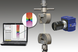
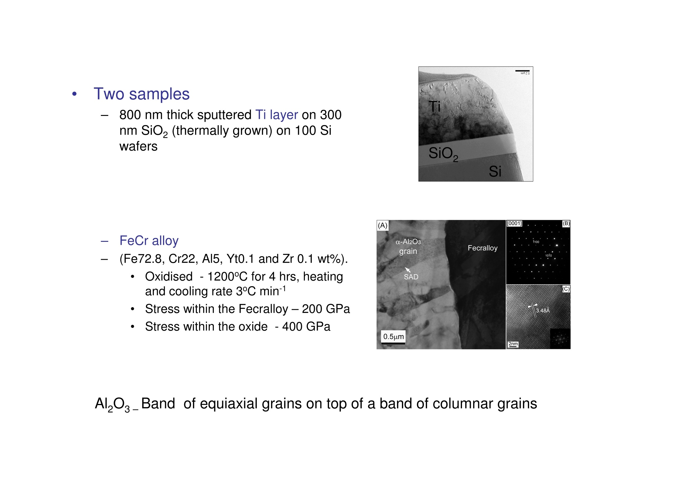
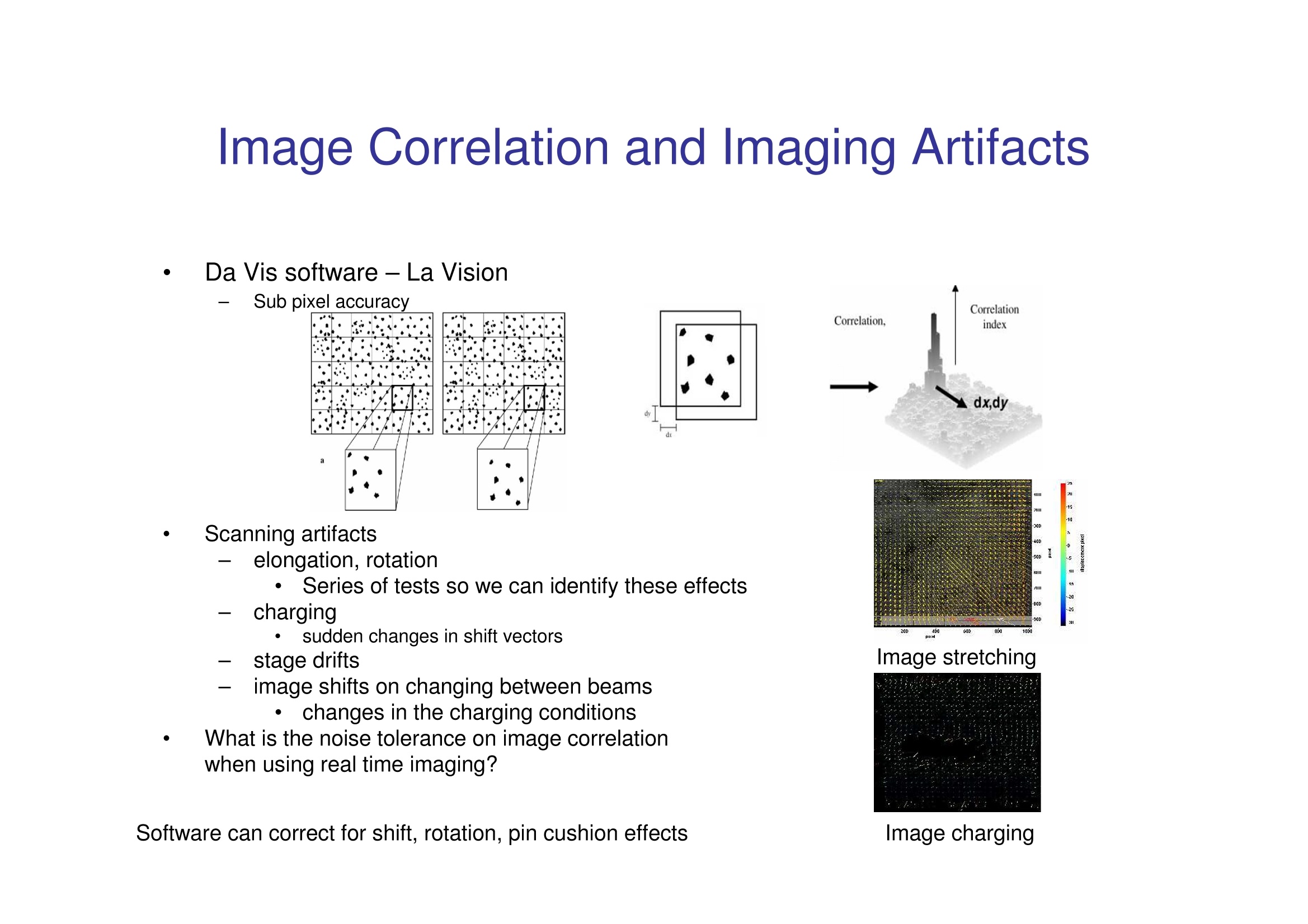
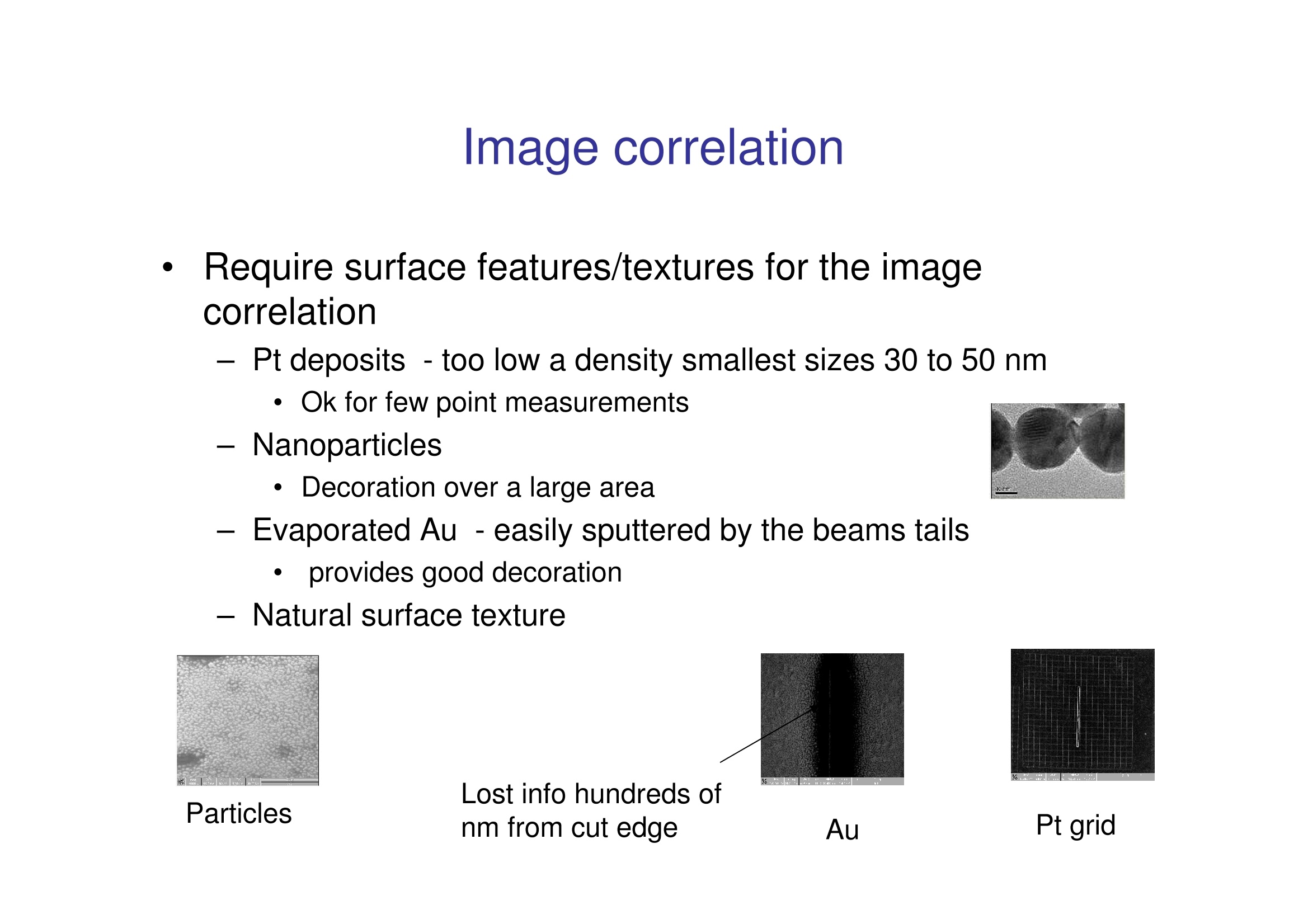
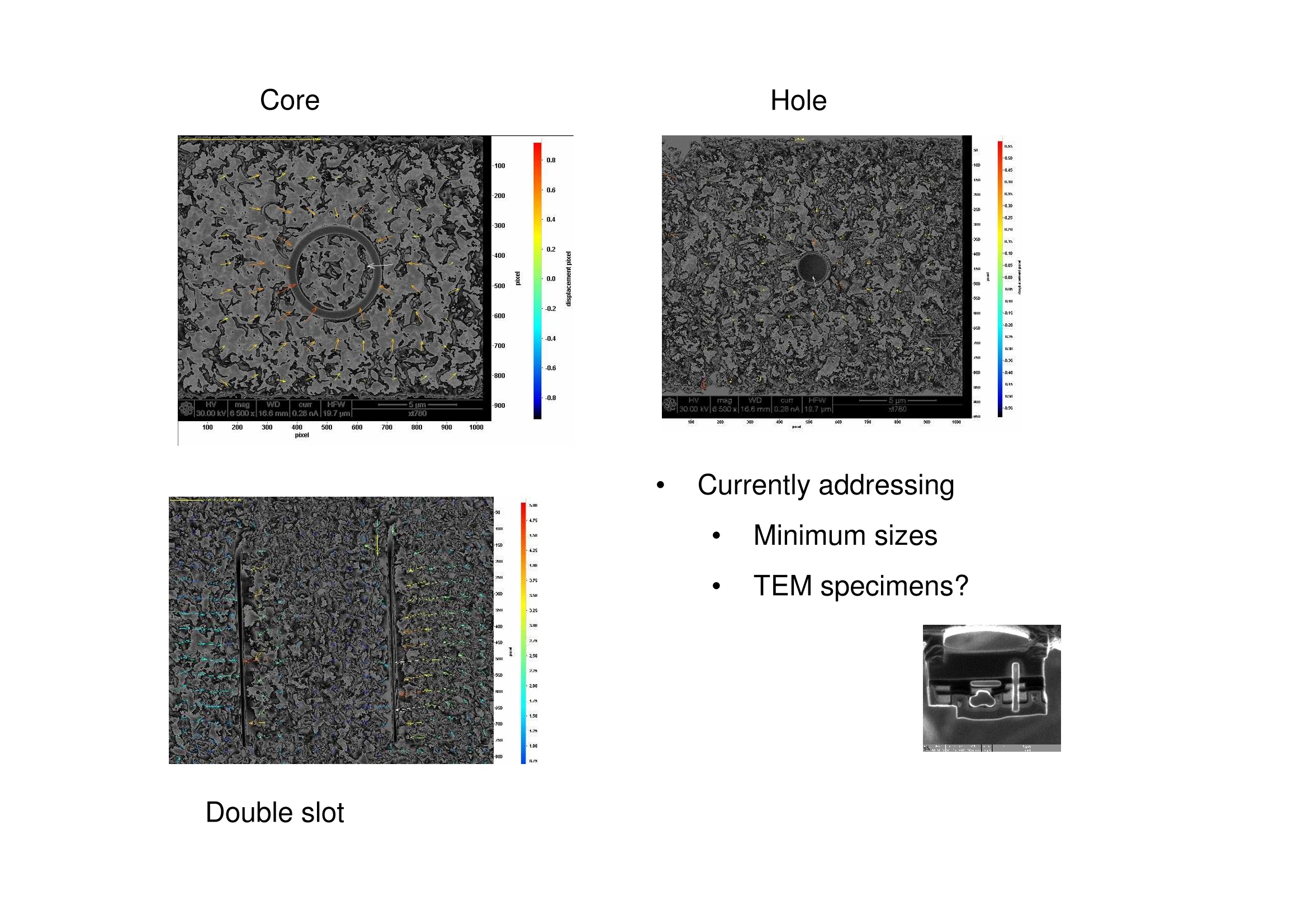
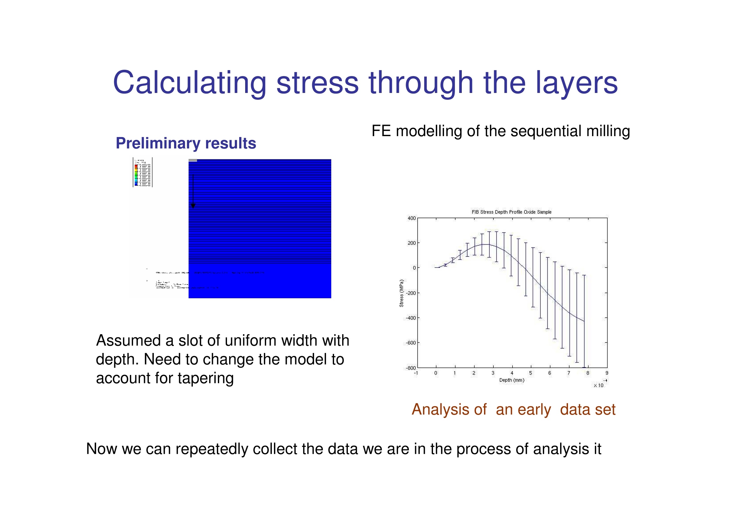
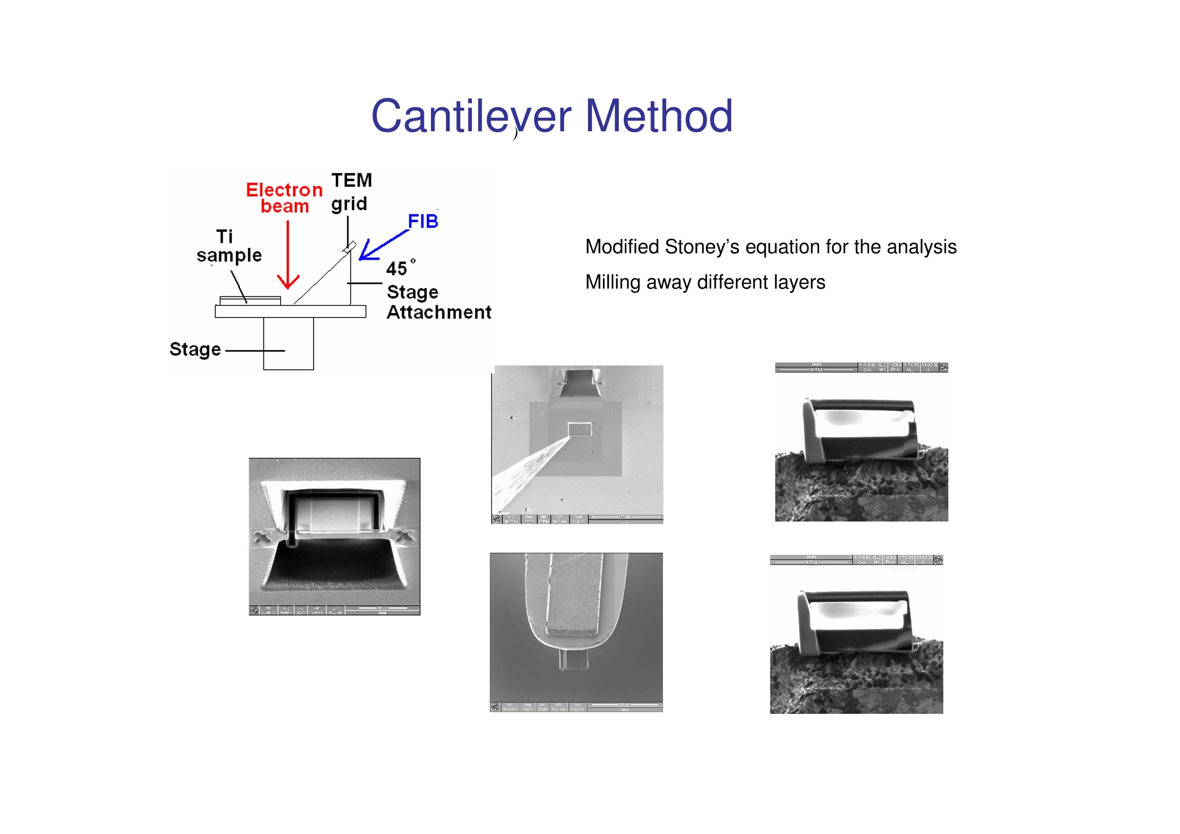
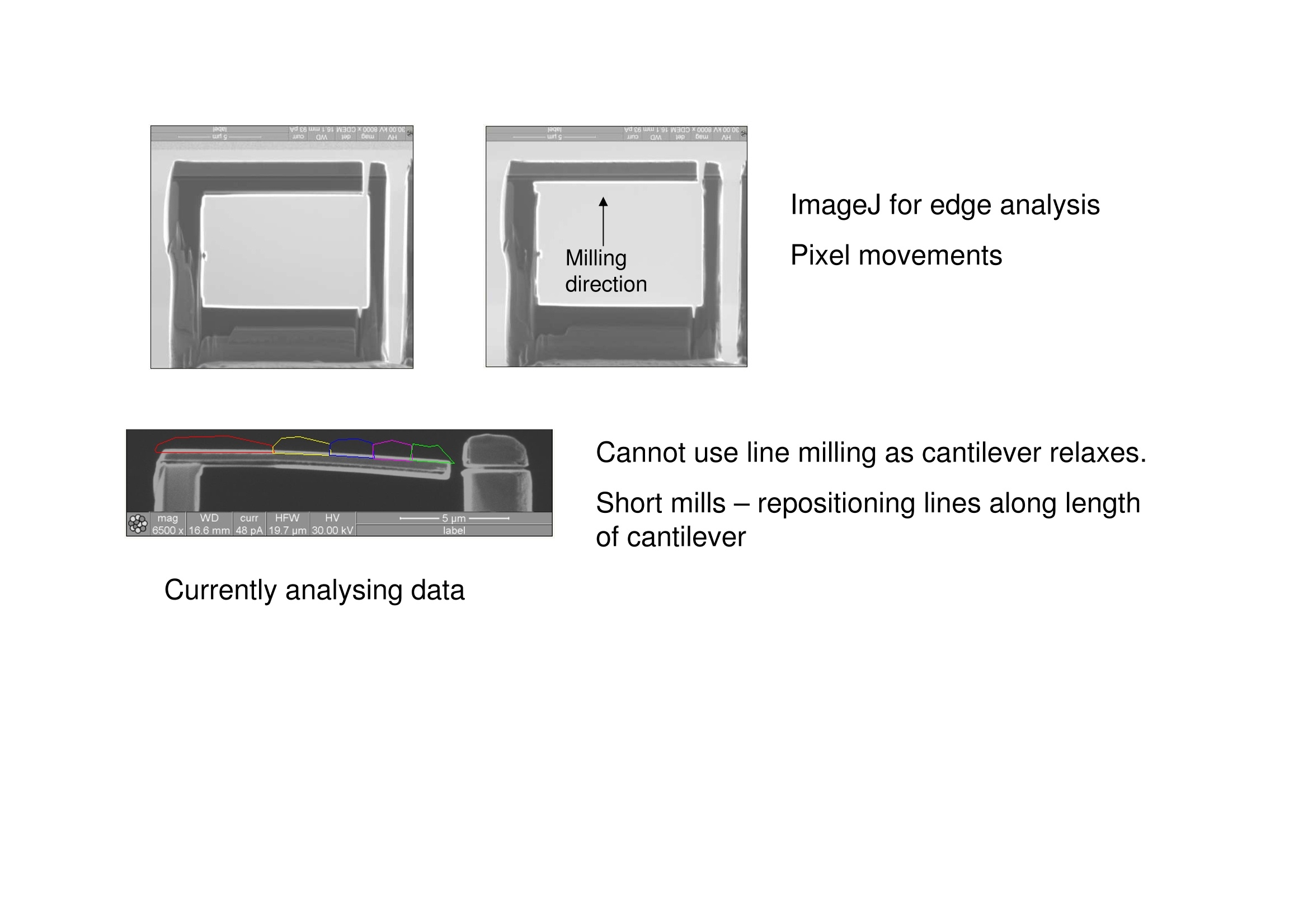
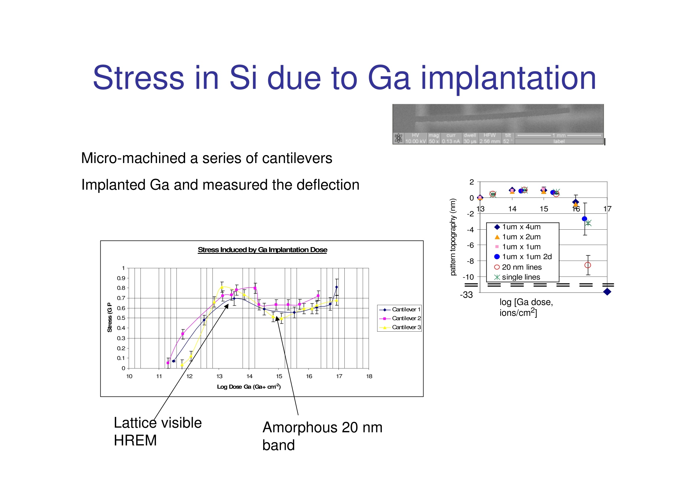
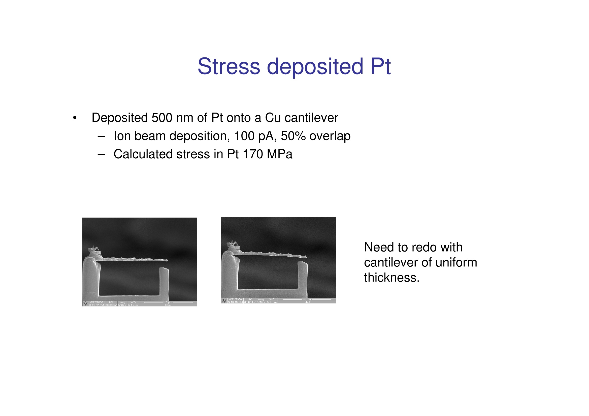
MANCHESTER1824 Core Multi Layer and Micro GradedStress Analysis Richard Langford, Xiaofeng Zhou, Christopher Gill, JoeKeller, Toby Ayers, Philip Withers Materials Science Centre, Manchester University, UK ●To develop a method to measure stressthrough coatings and layers Site specific analysis in sub micron areas,e.g. in grains with different orientations Slit method -N. Sabate, D. Vogel, A.Gollhart, J. Keller,and B.Michel. Applied Physics Letters 88,071910 (2006) Slit Milling Method Mill a slit and use image correlation to determine therelaxation of the material around the slit. Cantilever Method Prepare a slice from the material using the lift-outmethod and then cut a cantilever from the slice andmeasure the deflection. 。TTwo samples 800 nm thick sputtered Ti layer on 300nm SiO, (thermally grown) on 100 Siwafers 一FeCr allov (Fe72.8, Cr22, Al5, Yt0.1 and Zr 0.1 wt%). ●Oxidised-1200°℃ for 4 hrs, heatingand cooling rate 3°℃ min Stress within the Fecralloy-200 GPa Stress within the oxide-400 GPa Image Correlation and Imaging Artifacts Da Vis software -La Vision Sub pixel accuracy . Scanning artifacts elongation, rotation · Series of tests so we can identify these effects一charging sudden changes in shift vectors stage drifts Image stretching image shifts on changing between beams · changes in the charging conditions What is the noise tolerance on image correlationwhen using real time imaging? Image charging Image correlation Require surface features/textures for the imagecorreation - Pt deposits -too low a density smallest sizes 30 to 50 nm Ok for few point measurements - Nanoparticles ● Decoration over a large area -Evaporated Au - easily sputtered by the beams tails provides good decoration -Natural surface texture Lost info hundreds ofnm from cut edge Pt grid A Hole 要 Currently addressing Minimum sizes TEM specimens? Calculating stress through the layers FE modelling of the sequential milling Preliminary results Assumed a slot of uniform width withdepth. Need to change the model toaccount for tapering Analysis of an early data set Cantilever Method Modified Stoney's equation for the analysisMilling away different layers Stage- ImageJ for edge analysisPixel movements Cannot use line milling as cantilever relaxes. Short mills -repositioning lines along lengthof cantilever Stress in Si due to Ga implantation Micro-machined a series of cantileversImplanted Ga and measured the deflection Lattice visibleHREM Amorphous 20 nmband Deposited 500 nm of Pt onto a Cu cantilever - Ion beam deposition, 100 pA, 50% overlap Calculated stress in Pt 170 MPa Need to redo withcantilever of uniformthickness. EFUG Arcachon Al,_Band of equiaxial grains on top of a band of columnar grains
确定
还剩11页未读,是否继续阅读?

产品配置单

北京欧兰科技发展有限公司为您提供《微尺度固体材料结构中应力分析检测方案(其它无损检测仪器/设备)》,该方案主要用于其他中应力分析检测,参考标准--,《微尺度固体材料结构中应力分析检测方案(其它无损检测仪器/设备)》用到的仪器有LaVision StrainMaster材料应变形变成像测量系统、体视层析粒子成像测速系统(Tomo-PIV)
推荐专场


相关方案
更多
该厂商其他方案
更多