


方案详情
文
Corning® Advanced-Flow™ glass reactors are continuous flow reactors with hydraulic diameter in the range of millimetres. These devices make possible the switch of chemical reactions from batch mode to continuous processing through more efficient, more economical and safer processes. In addition, these reactors provide a platform for developing innovative chemistries that have never been considered industrially practical, either for hazard or yield reasons.
Corning proprietary apparatuses are compact, adaptable and scalable, optimizing overall production cost and quality of high-value specialty, fine, and pharmaceutical chemicals. Corning Advanced-Flow™ glass reactors are composed of multiple inter-connected glass devices having different designs, offering the advantages of process intensification and glass-specific qualities like transparency and very good chemical resistance.
This paper presents the comparison between experimental and CFD modelling results of a family of Corning glass devices aiming at achieving and maintaining very efficient mixing along the dwell time path. Numerical results are compared to experimental data: velocity profiles measured by micro-PIV means, pressure drop and heat transfer coefficient.
The satisfactory agreement between experimental results and CFD modelling proved the utility of numerical simulations in the development of new designs. Therefore, CFD tools help on one hand to predict the performance of new devices and on the other hand to optimize their design in order to improve their behaviour. Thus, CFD simulation facilitates the design and reduces time and cost for the investigation.
方案详情

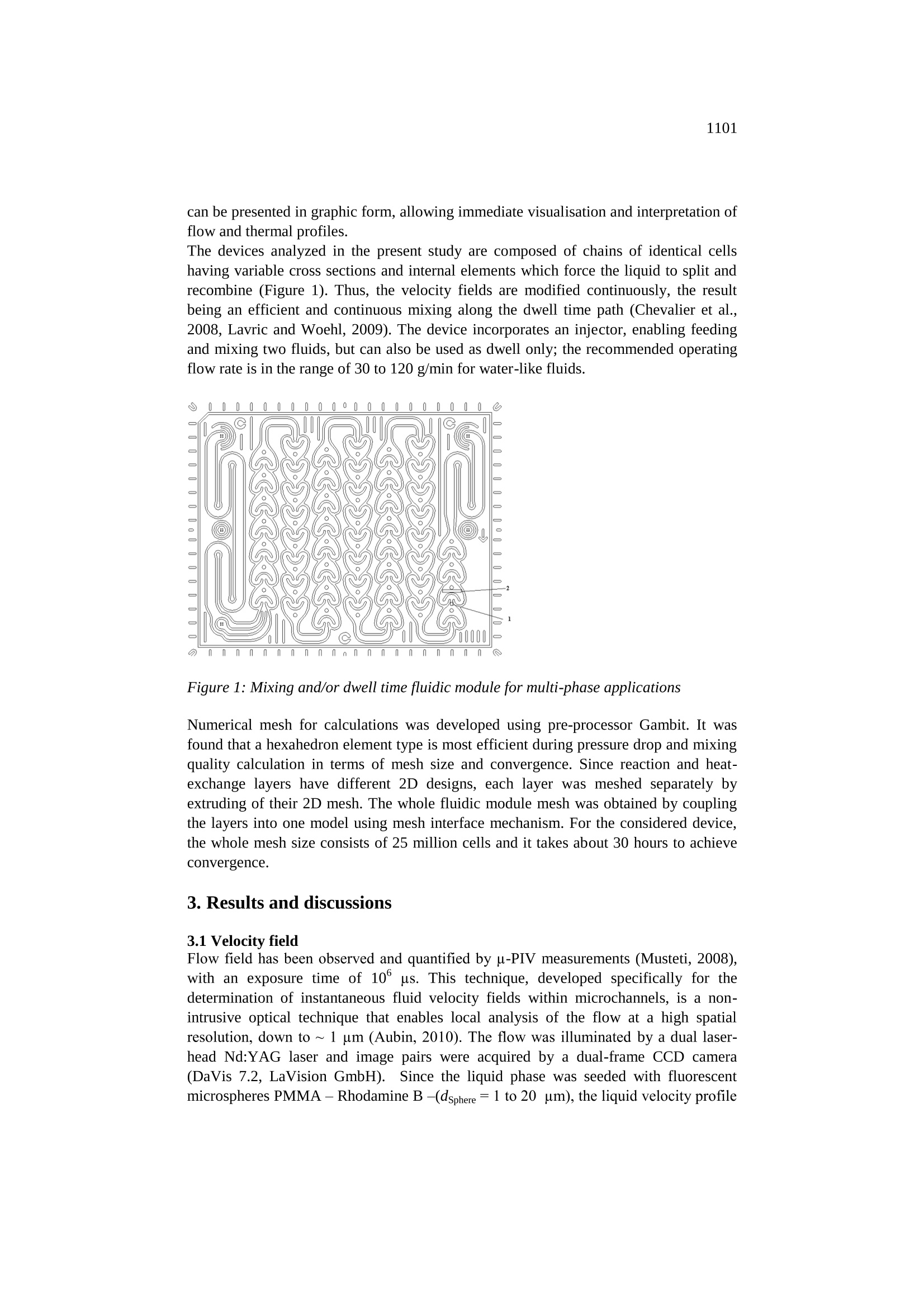
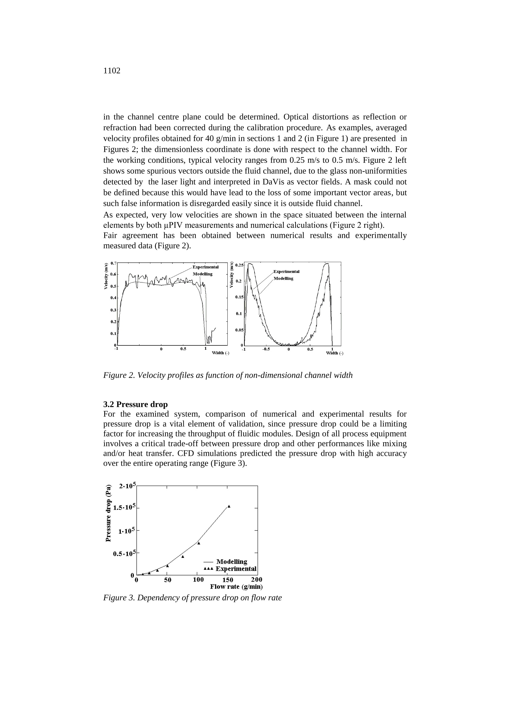
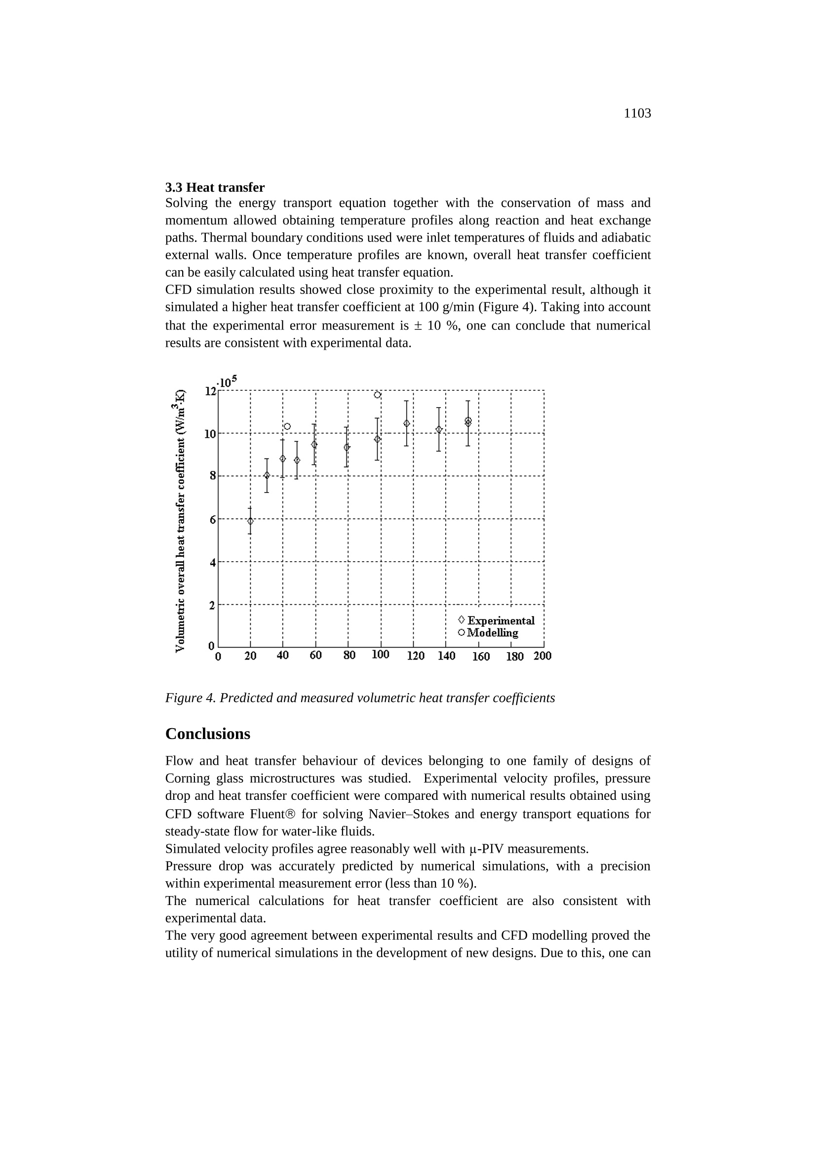
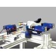
1099CHEMICAL ENGINEERING TRANSACTIONS Volume 21, 2010Editor J. J. Klemes, H. L. Lam, P. S. VarbanovCopyright O2010, AIDIC Servizi S.r.l., ISBN 978-88-95608-05-1 ISSN 1974-9791DOI: 10.3303/CET1021184 1100 CFD analysis of hydrodynamic and thermal behaviour ofAdvanced-FlowTM Reactors Mikhail S. Chivilikhin, Victoria Soboleva, Lev Kuandykov, Pierre Woehl, ElenaDaniela Lavric* Corning SNG, Corning Scientific, France Corning SAS, Corning European Technology Center, 7 bis Avenue de Valvins, 77210 Avon, France; lavricd@corning.com Corning@ Advanced-FlowTM glass reactors are continuous flow reactors with hydraulicdiameter in the range of millimetres. These devices make possible the switch ofchemical reactions from batch mode to continuous processing through more efficient,more economical and safer processes. In addition, these reactors provide a platform fordeveloping innovative chemistries that havenever been considered industriallypractical, either for hazard or yield reasons. Corning proprietary apparatuses are compact, adaptable and scalable, optimizing overallproduction cost and quality of high-value specialty, fine, and pharmaceutical chemicals.Corning Advanced-FlowTM glass reactors are composed of multiple inter-connectedglass devices having different designs, offering the advantages of process intensificationand glass-specific qualities like transparency and very good chemical resistance. This paper presents the comparison between experimental and CFD modelling results ofa family of Corning glass devices aiming at achieving and maintaining very efficientmixing along the dwell time path. Numerical results are compared to experimental data:velocity profiles measured by micro-PIV means, pressure drop and heat transfercoefficient. The satisfactory agreement between experimental results and CFD modelling proved theutility of numerical simulations in the development of new designs. Therefore, CFDtools help on one hand to predict the performance of new devices and on the other handto optimize their design in order to improve their behaviour. Thus, CFD simulationfacilitates the design and reduces time and cost for the investigation. 1.Introduction Process miniaturization and microreaction technology provide opportunimproving process capability and control in chemical/biochemical synthesis and canallow safer and more efficient chemical/biochemical kinetic investigations. Comparedto normal scale reactors, microreactors have the following advantages: decrease oflinear dimensions, increase of surface to volume ratio, fast and efficient processdevelopment, decreased potential of environmental impact, and increased safety. Thelarge surface-to-volume ratios of the micro channels51improve heat transfer for ( Please cite this a rticle as: Chivilikhi n M . S. , Soboleva V., K uandykov L. , Wo e hl P. a nd Lavr i c E. D . , (2010), CFD analysis ofhydrodynamic a nd thermal behaviour of Advanced-FlowM r e actors, C hemical E ngineering Transactions , 21, 1099-1104 DOI: 10.3303/CET1021184 ) exothermic reactions, thus preventing either thermal degradation or explosive evolution(Mae, 2007,Watts and Wiles, 2007, Hessel et al., 2008). The operating conditions,controlled better and more accurately than for classical reactors, are more aggressive,attaining regimes previously out of reach, which imply higher yields, making theseparation process cost effective. Side reactions could be avoided or reduced byoperating the microreactor in a tight window of parameters where the process selectivityand product purity have the highest values. Microreactor technology provides relatively simpleand quickmeanstowardscommercialization of a process. The economic production of large numbers ofmicroreactors enables the shift from the present production paradigm of batch processand“scaling up”to a new paradigm of continuous process and “numbering up” i.e.,running numerous microreactors in parallel for mass production (Lavric and Woehl,2009). This would lead to short lead times from laboratory development to industrialproduction as well as the ability to produce chemicals on demand on-site. Corning has developed proprietary continuous micro-reactor processing technologiesthat are compact, adaptable and scalable, optimizing overall quality of high-valuespecialty, fine, and pharmaceutical chemicals. The devices, which are as small asbeneficially needed, are glass-made, offering the advantages of process intensificationand glass-specific qualities like transparency and very good chemical resistance.Corning fluidic modules are devices composed of a reaction chamber stacked between twoheat exchanger layers, thus integrating mixing and/or dwell time with heat transfer. Computational fluid dynamics (CFD) is a powerful simulation tool, based on numericalsolutions of equations for the conservation of mass,momentum, energy, offering analternative technique to traditional experimental methods for accelerating equipmentdesign and optimization while gaining additional fundamental understanding oftransport processes. Once validated, CFD can be utilized for design purposes. Before CFD can be used confidently, the results must be validated against experimentalvalues. The primary benefit of CFD models lies within their capacity for testing andoptimizing numerous scenarios quickly compared to designing and building anexperimental/laboratory model. CFD has been widely used to investigate the characteristics of flow and heat transferinside microfluidic devices (Tomomura et al., 2002, Haeberle et al., 2005, Feng andYang, 2009). The velocity field, pressure drop and temperature profiles in a device were computedassuming steady-state, laminar flow in the reaction channel and turbulent flow on heatexchange side. Navier-Stokes and energy transport (governing) equations have beensolved for water, imposing as boundary conditions the inlet velocity (flow rate) and exitpressure for a device having the reactive channel of 1.1 mm height. Numerical resultsare compared to experimental data: velocity profiles measured by micro particle imagevelocimetry (u-PIV) means, pressure drop and heat transfer coefficient. The satisfactory agreement between experimental results and CFD modelling provedthe utility of numerical simulations in the development of new designs. 2. Device Typically, CFD analysis involves the decomposition of the structure into a mesh of cellsor elements, performing the fluid-flow calculations at the nodes of each cell. The results can be presented in graphic form, allowing immediate visualisation and interpretation offlow and thermal profiles. The devices analyzed in the present study are composed of chains of identical cellshaving variable cross sections and internal elements which force the liquid to split andrecombine (Figure 1). Thus, the velocity fields are modified continuously, the resultbeing an efficient and continuous mixing along the dwell time path (Chevalier et al.,2008, Lavric and Woehl, 2009). The device incorporates an injector, enabling feedingand mixing two fluids, but can also be used as dwell only; the recommended operatingflow rate is in the range of 30 to 120 g/min for water-like fluids. Figure 1: Mixing and/or dwell time fluidic module for multi-phase applications Numerical mesh for calculations was developed using pre-processor Gambit. It wasfound that a hexahedron element type is most efficient during pressure drop and mixingquality calculation in terms of mesh size and convergence. Since reaction and heat-exchange layers have different 2D designs, each layer was meshed separately byextruding of their 2D mesh. The whole fluidic module mesh was obtained by couplingthe layers into one model using mesh interface mechanism. For the considered device,the whole mesh size consists of 25 million cells and it takes about 30 hours to achieveconvergence. 3. Results and discussions 3.1 Velocity field Flow field has been observed and quantified by u-PIV measurements (Musteti, 2008),with an exposure time of 10° us. This technique, developed specifically for thedetermination of instantaneous fluid velocity fields within microchannels, is a non-intrusive optical technique that enables local analysis of the flow at a high spatialresolution, down to ~1 um (Aubin, 2010). The flow was illuminated by a dual laser-head Nd:YAG laser and image pairs were acquired by a dual-frame CCD camera(DaVis 7.2, LaVision GmbH). Since the liquid phase was seeded with fluorescentmicrospheres PMMA-Rhodamine B-(dsphere = to 20 um), the liquid velocity profile in the channel centre plane could be determined. Optical distortions as reflection orrefraction had been corrected during the calibration procedure. As examples, averagedvelocity profiles obtained for 40 g/min in sections 1 and 2 (in Figure 1) are presented inFigures 2; the dimensionless coordinate is done with respect to the channel width. Forthe working conditions, typical velocity ranges from 0.25 m/s to 0.5 m/s. Figure 2 leftshows some spurious vectors outside the fluid channel, due to the glass non-uniformitiesdetected by the laser light and interpreted in DaVis as vector fields. A mask could notbe defined because this would have lead to the loss of some important vector areas,butsuch false information is disregarded easily since it is outside fluid channel. As expected, very low velocities are shown in the space situated between the internalelements by both uPIV measurements and numerical calculations (Figure 2 right). Fair agreement has been obtained between numerical results and experimentallymeasured data (Figure 2). Figure 2. Velocity profiles as function ofnon-dimensional channel width 3.2 Pressure drop For the examined system, comparison of numerical and experimental results forpressure drop is a vital element of validation, since pressure drop could be a limitingfactor for increasing the throughput of fluidic modules. Design of all process equipmentinvolves a critical trade-off between pressure drop and other performances like mixingand/or heat transfer. CFD simulations predicted the pressure drop with high accuracyover the entire operating range (Figure 3). Figure 3. Dependency of pressure drop on flow rate 3.3 Heat transfer Solving the energy transport equation together with the conservation of mass andmomentum allowed obtaining temperature profiles along reaction and heat exchangepaths. Thermal boundary conditions used were inlet temperatures of fluids and adiabaticexternal walls. Once temperature profiles are known, overall heat transfer coefficientcan be easily calculated using heat transfer equation. CFD simulation results showed close proximity to the experimental result, although itsimulated a higher heat transfer coefficient at 100 g/min (Figure 4). Taking into accountthat the experimental error measurement is ± 10 %, one can conclude that numericalresults are consistent with experimental data. Figure 4. Predicted and measured volumetric heat transfer coefficients Conclusions Flow and heat transfer behaviour of devices belonging to one family of designs ofCorning glass microstructures was studied. Experimental velocity profiles, pressuredrop and heat transfer coefficient were compared with numerical results obtained usingCFD software Fluent@ for solving Navier-Stokes and energy transport equations forsteady-state flow for water-like fluids. Simulated velocity profiles agree reasonably well with u-PIV measurements. Pressure drop was accurately predicted by numerical simulations, with a precisionwithin experimental measurement error (less than 10 %). The numerical calculations for heat transfer coefficient are also consistent withexperimental data. The very good agreement between experimental results and CFD modelling proved theutility of numerical simulations in the development of new designs. Due to this, one can conclude that CFD modelling can be used to develop and optimise new designs,reducing time and cost for the investigation. Acknowledgements Arnaud Abrial and Carine Cerato are kindly acknowledged for their commitment andthorough experimental work. The authors thank Ana Daniela Musteti for PIVmeasurements, Olivier Lobet and Jean-Marc Jouanno for fruitful discussions. References Aubin J., Ferrando M. and Jiricny V.,2010,Current methods for characterising mixingand flow in microchannels, Chem. Eng. Sci. 65,2065-2093. Chevalier B., Lavric E. D., Cerato-Noyerie C., Horn C. and Woehl1]P., 2008,Microreactors for industrial multi-phase applications. Test reactions to developinnovative glass microstructure design, Chemistry Today, 26,1-4. Haeberle S., Brenner T., Schlosser HP., Zengerle R. and Ducree J., 2005, Centrifugalmicromixer, Chem. Eng. Tech.,28, 613-616. Hessell V., Knobloch Ch. and Lowe, H., 2008, Review on Patents in Microreactor andMicro Process Engineering, Recent Patents on Chemical Engineering, 1, 1-16. Lavric E.D. and Woehl P., Advanced-FlowTM glass reactors for seamless scale-up,Chemistry Today 27, 45-48. Mae K., 2007, Advanced chemical processing using microspace, Chem. Eng. Sci.62. 4842-4851. Musteti iA.,2008.MSc Dissertation, University POLITEHNICAA of Bucharest.Romania. Tonomura O., Kano M., Hasebe H. and Hashimoto I.,2002, CFD-based Analysis ofHeat Transfer and Flow Pattern in Plate-Fin Micro Heat Exchangers, PSE Asia(lastaccessed 22/05/2010) Watts P. and Wiles C., 2007, Recent advances in synthetic micro reaction technology,Chem. Comm. 5, 443-467. Wei-Feng Fanga W F. and Yang JT., 2009, A novel microreactor with 3D rotating flowto boost fluid reaction and mixing of viscous fluids, Sensors and Actuators B 140,629-642.
确定
还剩4页未读,是否继续阅读?

产品配置单


北京欧兰科技发展有限公司为您提供《流体中速度场检测方案 》,该方案主要用于其他中速度场检测,参考标准--,《流体中速度场检测方案 》用到的仪器有自适应粒子成像测速场仪(PIV)、德国LaVision PIV/PLIF粒子成像测速场仪、显微粒子成像测速系统(Micro PIV)
推荐专场


相关方案
更多
该厂商其他方案
更多