


方案详情
文
Angular Domain Imaging (ADI) employs an angular filter array to accept photons within a small acceptance angle
along the axis of an aligned laser light source and preferentially reject scattered light. Simulations show that the
accepted photons travel the shortest paths between source and detector and are therefore the earliest to arrive. We
fabricated angular filter arrays using silicon bulk micromachining and found that an array of 60 μm square shape microtunnels
1 cm in length accepted photons within 0.48 degree of axis of the micro-tunnels. This small acceptance angle
rejected most of the scattered light and sub-millimeter resolution targets could be resolved in a few centimeters of turbid
medium with at least six times reduced mean free path. ADI through media with higher scattering coefficients was not
achievable due to unwanted acceptance of late arriving scattered photons. To reject the late arriving photons, we added
time-domain filtration and linear polarization to ADI. The implementation of a time-gated camera, a 780 nm femtosecond
pulsed laser, and linear polarization to our ADI system resulted in improved image contrast. The use of ADI
with time-gating (gate width 250 ps) and linear polarization enabled visualization of sub-millimeter absorbing objects
with approximately eight times higher image contrast compared to ADI in a scattering medium equivalent to six times
reduced mean free path.
方案详情

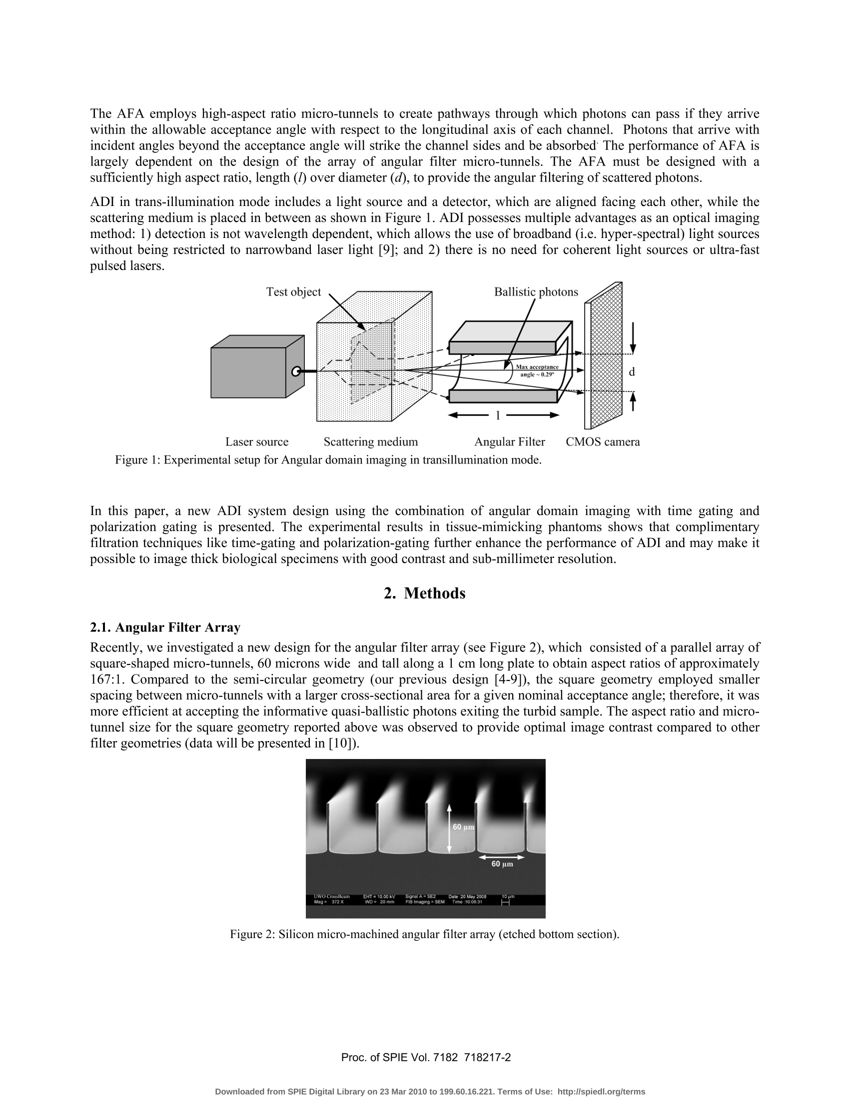
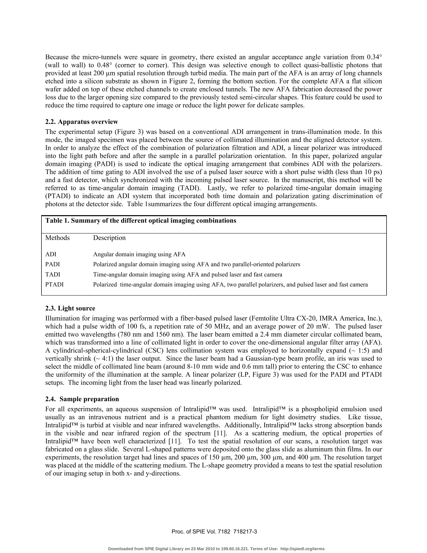
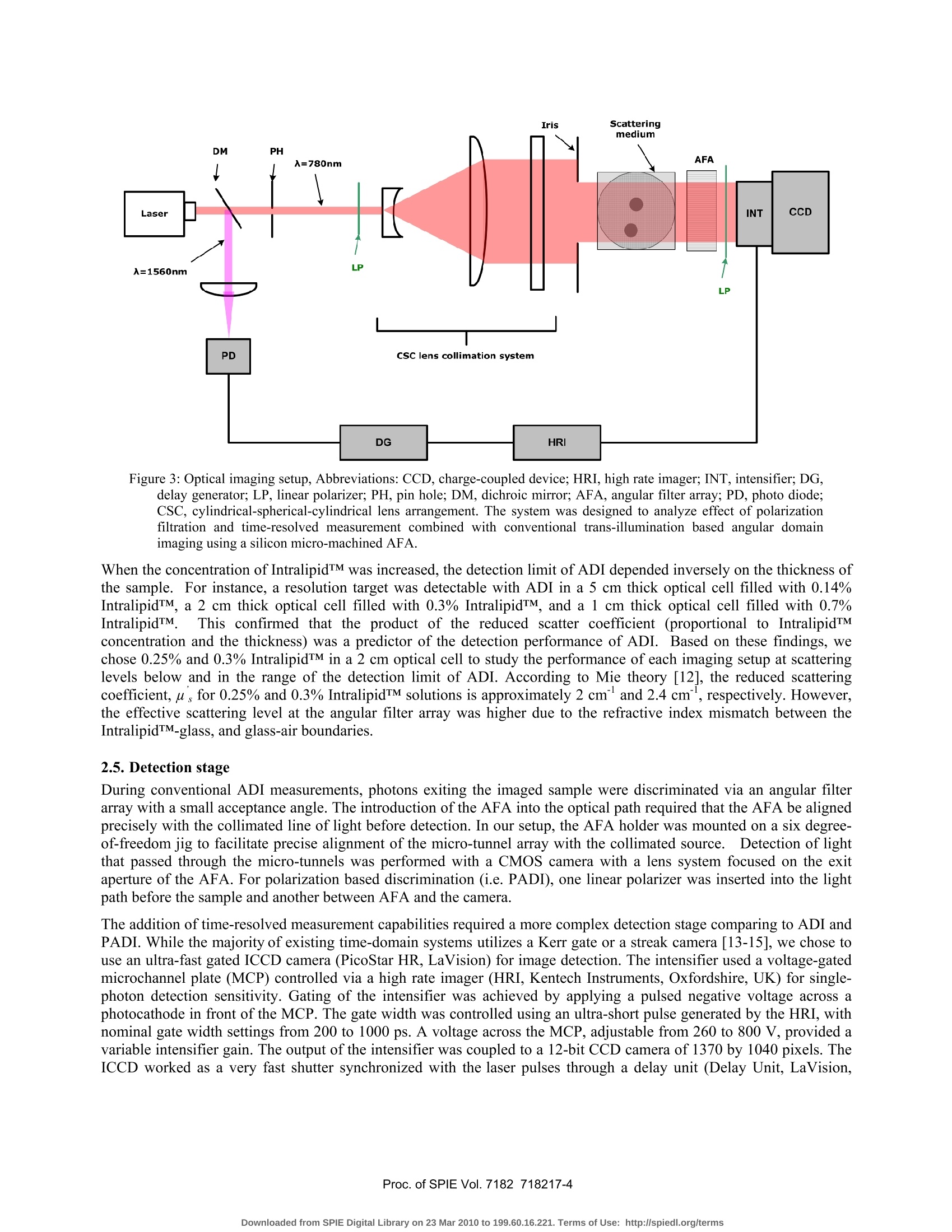
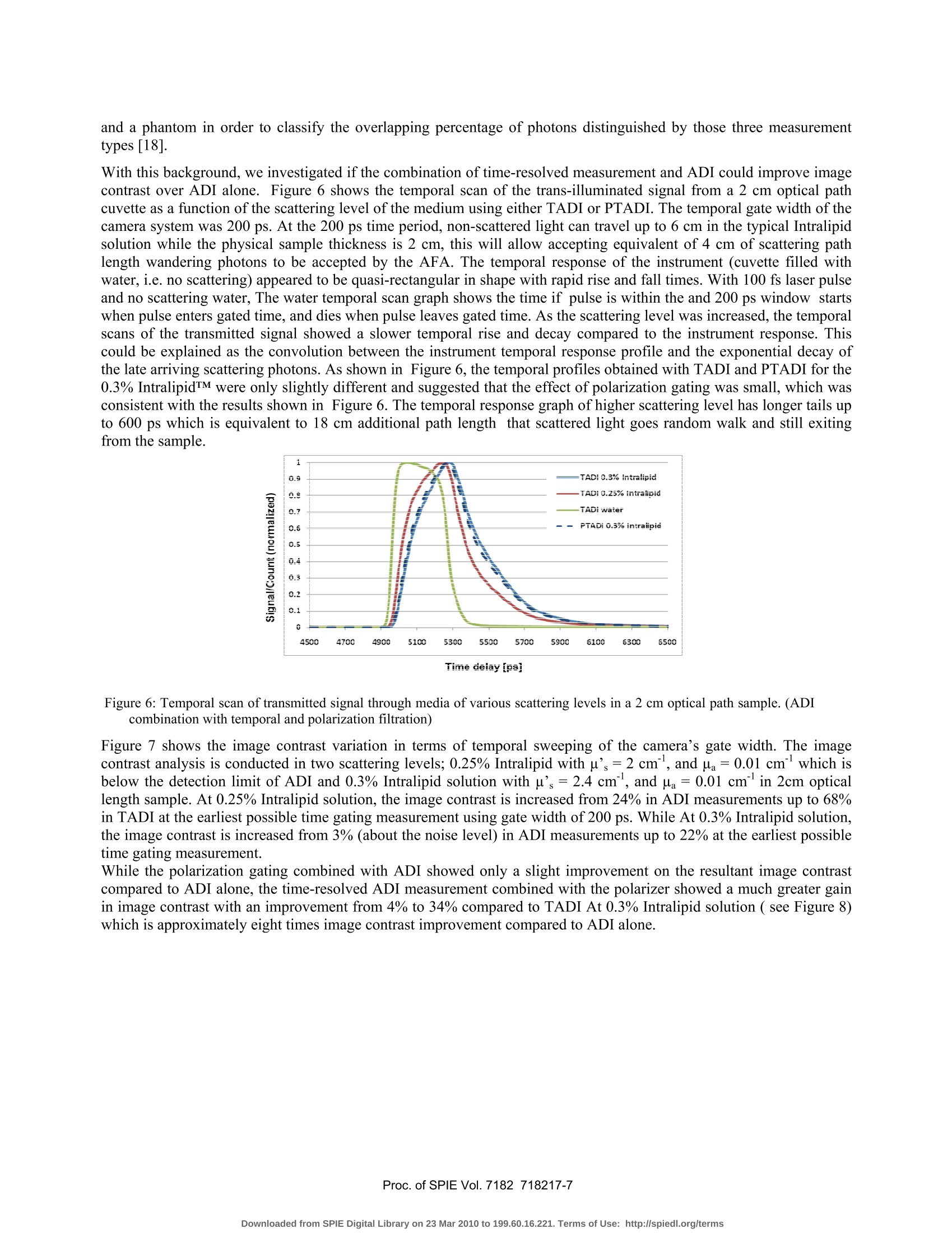
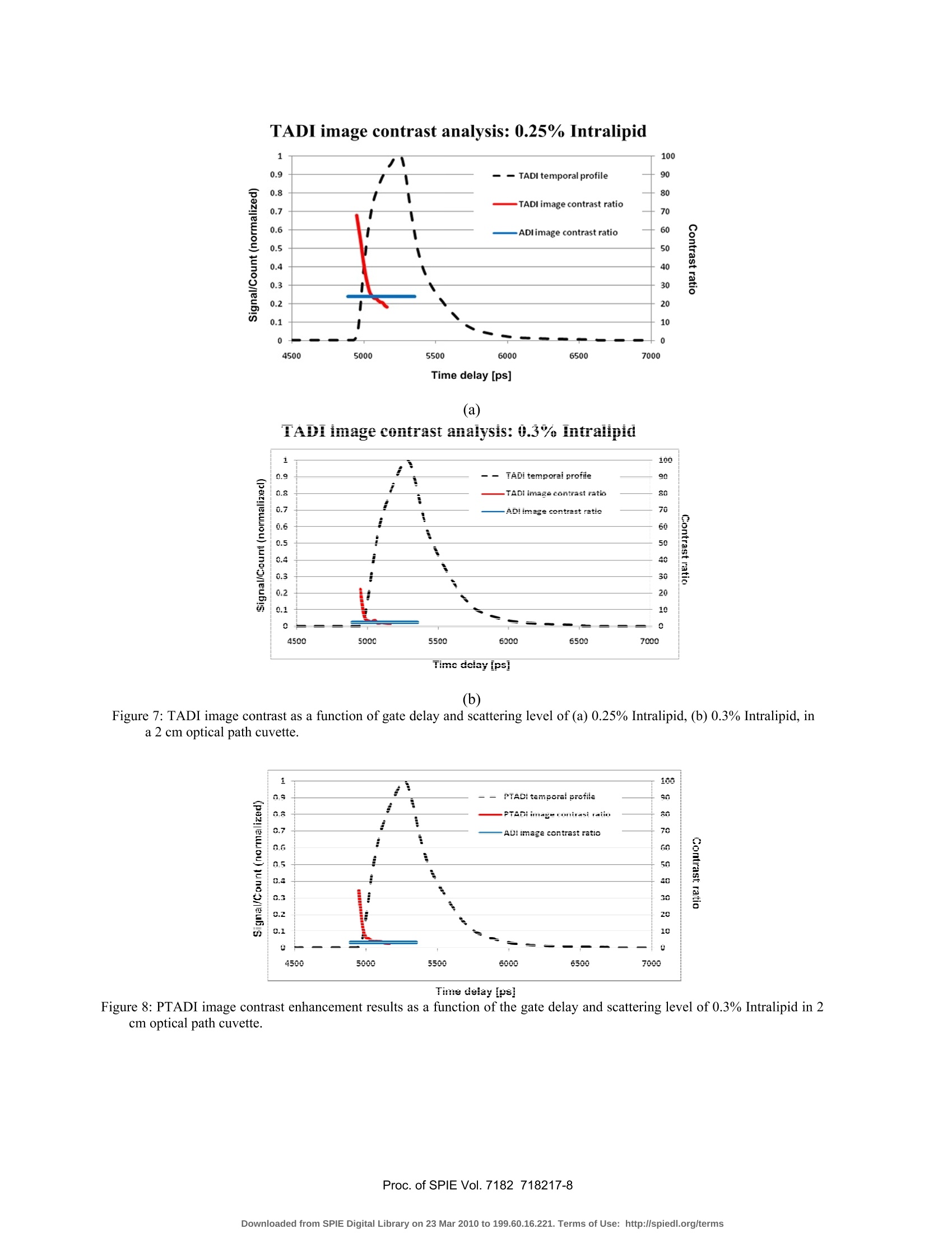
TADI image contrast analysis: 0.25% Intralipid Effect of time-gating and polarization-discrimination of propagatinglight in turbid media during Angular Domain Imaging (ADI) Fartash Vasefi2, Eldon Ng’3, Bozena Kaminska', Glenn H. Chapman, Jeffrey J.L. Carson?3The School of Engineering Science, Simon Fraser University, Burnaby, BC, CanadaImaging Program, Lawson Health Research Institute, London, ON, CanadaMedical Biophysics, University of Western Ontario, London,ON, Canada ABSTRACT Angular Domain Imaging (ADI) employs an angular filter array to accept photons within a small acceptance anglealong the axis of an aligned laser light source and preferentially reject scattered light. Simulations show that theaccepted photons travel the shortest paths between source and detector and are therefore the earliest to arrive. Wefabricated angular filter arrays using silicon bulk micromachining and found that an array of 60 um square shape micro-tunnels 1 cm in length accepted photons within 0.48 degree of axis of the micro-tunnels. This small acceptance anglerejected most of the scattered light and sub-millimeter resolution targets could be resolved in a few centimeters of turbidmedium with at least six times reduced mean free path. ADI through media with higher scattering coefficients was notachievable due to unwanted acceptance of late arriving scattered photons. To reject the late arriving photons, we addedtime-domain filtration and linear polarization to ADI. The implementation of a time-gated camera, a 780 nm femto-second pulsed laser, and linear polarization to our ADI system resulted in improved image contrast. The use of AD]with time-gating (gate width 250 ps) and linear polarization enabled visualization of sub-millimeter absorbing objectswith approximately eight times higher image contrast compared to ADI in a scattering medium equivalent to six timesreduced mean free path. Keywords: Optical imaging, turbid media, time gating, micromachining angular filters, quasi-ballistic photons,polarization gating, Multimode optical imaging 1. Introduction Optical imaging methods are highly useful for the study of biological tissues and their associated physiologicalcondition. Contrast between different tissue components is available in the form of differing optical absorption andscattering characteristics [1]. For example, the optical properties of tissues, specifically for those containing oxygenatedand de-oxygenated blood, are properly discriminated by using light in the red and near infrared spectrum. For thisreason, an increase in blood content may be detected, which is an indication of rapid cancer cell growth [2]. Malignanttissue usually has a larger absorption coefficient than normal tissue due to its higher blood content [3]. As a result,optical detection of abnormalities can be considered sensitive enough for early detection ofvarious kinds of cancers. The most important challenge faced by optical imaging in biological tissue is the inherent high level of light scattering.In highly scattering media, the bulk number of the photons follows random-walk trajectories. This makes image-carrying photon detection more difficult than most other medical imaging modalities such as X-ray, in which thephotons penetrate the tissue with ballistic trajectories [1]. Overcoming this problem is the main challenge in high-resolution optical imaging. This paper presents a variation of the Angular Domain Imaging (ADI) method, whichoperates by selecting the informative photons and rejecting those that are multiply scattered. The new ADI methodologyuses a combination of three different ways to extract the non-scattered light including time-gating, polarization-gating,and time plus polarization gating. The experimental approach was to test the overall imaging efficiency of the ADIvariants in phantoms with optical scatter characteristics similar to tissue. The ADI method operates by selecting non-scattered ballistic and quasi-ballistic light closely confined within a smallangle of the photon trajectories of the initial light source while filtering out highly scattered light. The method is basedupon the observation that scattered light tends to have a nearly uniform angular distribution [4-9]. Thus, highly scatteredlight can be filtered out based on angle by use of an angular filter array (AFA; see Figure 1), while allowing ballisticand quasi-ballistic light within the acceptance angle of the AFA to pass through to the detector. The AFA employs high-aspect ratio micro-tunnels to create pathways through which photons can pass if they arrivewithin the allowable acceptance angle with respect to the longitudinal axis of each channel. Photons that arrive withincident angles beyond the acceptance angle will strike the channel sides and be absorbed The performance of AFA islargely dependent on the design of the array of angular filter micro-tunnels. The AFA must be designed with asufficiently high aspect ratio, length (l) over diameter (d), to provide the angular filtering of scattered photons. ADI in trans-illumination mode includes a light source and a detector, which are aligned facing each other, while thescattering medium is placed in between as shown in Figure1. ADI possesses multiple advantages as an optical imagingmethod: 1) detection is not wavelength dependent, which allows the use of broadband (i.e.hyper-spectral) light sourceswithout being restricted to narrowband laser light [9]; and 2) there is no need for coherent light sources or ultra-fastpulsed lasers. Figure 1: Experimental setup for Angular domain imaging in transillumination mode. In this paper, a new ADI system design using the combination of angular domain imaging with time gating andpolarization gating is presented. The experimental results in tissue-mimicking phantoms shows that complimentaryfiltration techniques like time-gating and polarization-gating further enhance the performance of ADI and may make itpossible to image thick biological specimens with good contrast and sub-millimeter resolution. 2. Methods 2.1. Angular Filter Array Recently, we investigated a new design for the angular filter array (see Figure2), which consisted of a parallel array ofsquare-shaped micro-tunnels, 60 microns wide and tall along a 1 cm long plate to obtain aspect ratios of approximately167:1. Compared to the semi-circular geometry(our previous design [4-9]), the square geometry employed smallerspacing between micro-tunnels with a larger cross-sectional area for a given nominal acceptance angle; therefore, it wasmore efficient at accepting the informative quasi-ballistic photons exiting the turbid sample. The aspect ratio and micro-tunnel size for the square geometry reported above was observed to provide optimal image contrast compared to otherfilter geometries (data will be presented in [10]). Figure 2: Silicon micro-machined angular filter array (etched bottom section). Because the micro-tunnels were square in geometry, there existed an angular acceptance angle variation from 0.34°(wall to wall) to 0.48°(corner to corner). This design was selective enough to collect quasi-ballistic photons thatprovided at least 200 um spatial resolution through turbid media. The main part of the AFA is an array of long channelsetched into a silicon substrate as shown in Figure 2, forming the bottom section. For the complete AFA a flat siliconwafer added on top of these etched channels to create enclosed tunnels. The new AFA fabrication decreased the powerloss due to the larger opening size compared to the previously tested semi-circular shapes. This feature could be used toreduce the time required to capture one image or reduce the light power for delicate samples.S. 2.2. Apparatus overview The experimental setup (Figure 3) was based on a conventional ADI arrangement in trans-illumination mode. In thismode, the imaged specimen was placed between the source of collimated illumination and the aligned detector system.In order to analyze the effect of the combination of polarization filtration and ADI, a linear polarizer was introducedinto the light path before and after the sample in a parallel polarization orientation. In this paper, polarized angulardomain imaging (PADI) is used to indicate the optical imaging arrangement that combines ADI with the polarizers.The addition of time gating to ADI involved the use of a pulsed laser source with a short pulse width (less than 10 ps)and a fast detector, which synchronized with the incoming pulsed laser source. In the manuscript, this method will bereferred to as time-angular domain imaging (TADI). Lastly, we refer to polarized time-angular domain imaging(PTADI) to indicate an ADI system that incorporated both time domain and polarization gating discrimination ofphotons at the detector side. Table 1summarizes the four different optical imaging arrangements. Table 1. Summary of the different optical imaging combinations Table 1. Summary of the different optical imaging combinations Methods Description ADI Angular domain imaging using AFA PADI Polarized angular domain imaging using AFA and two parallel-oriented polarizers TADI Time-angular domain imaging using AFA and pulsed laser and fast camera PTADI Polarized time-angular domain imaging using AFA, two parallel polarizers, and pulsed laser and fast camera 2.3. Light source Illumination for imaging was performed with a fiber-based pulsed laser (Femtolite Ultra CX-20, IMRA America, Inc.),which had a pulse width of 100 fs, a repetition rate of 50 MHz, and an average power of 20 mW. The pulsed laseremitted two wavelengths (780 nm and 1560 nm). The laser beam emitted a 2.4 mm diameter circular collimated beam,which was transformed into a line of collimated light in order to cover the one-dimensional angular filter array (AFA).A cylindrical-spherical-cylindrical (CSC) lens collimation system was employed to horizontally expand (~1:5) andvertically shrink (~4:1) the laser output. Since the laser beam had a Gaussian-type beam profile, an iris was used toselect the middle of collimated line beam (around 8-10 mm wide and0.6 mm tall) prior to entering the CSC to enhancethe uniformity of the illumination at the sample. A linear polarizer (LP, Figure 3) was used for the PADI and PTADIsetups. The incoming light from the laser head was linearly polarized. 2.4. Sample preparation For all experiments, an aqueous suspension of IntralipidTM was used. IntralipidTM is a phospholipid emulsion usedusually as an intravenous nutrient and is a practical phantom medium for light dosimetry studies.. Like tissue.IntralipidTM is turbid at visible and near infrared wavelengths. Additionally, IntralipidTM lacks strong absorption bandsin the visible and near infrared region of the spectrum [11].As a scattering medium, the optical properties ofIntralipidTM have been well characterized [11]. To test the spatial resolution of our scans, a resolution target wasfabricated on a glass slide. Several L-shaped patterns were deposited onto the glass slide as aluminum thin films. In ourexperiments, the resolution target had lines and spaces of 150 um, 200 um, 300 um, and 400 um. The resolution targetwas placed at the middle of the scattering medium. The L-shape geometry provided a means to test the spatial resolutionof our imaging setup in both x- and y-directions. Figure 3: Optical imaging setup, Abbreviations: CCD, charge-coupled device; HRI, high rate imager; INT, intensifier; DG,delay generator;LP, linear polarizer; PH, pin hole; DM, dichroic mirror; AFA, angular filter array; PD, photo diode;CSC, cylindrical-spherical-cylindrical lens arrangement. The system was designed to analyze effect of polarizationfiltration and time-resolved measurement combined with conventional trans-illumination based angular domainimaging using a silicon micro-machined AFA. When the concentration of IntralipidTM was increased, the detection limit of ADI depended inversely on the thickness ofthe sample. For instance, a resolution target was detectable with ADI in a 5 cm thick optical cell filled with 0.14%IntralipidTM, a 2 cm thick optical cell filled with 0.3% IntralipidTM, and a 1 cm thick optical cell filled with 0.7%IntralipidTM. This confirmed that the product of the reduced scatter coefficient (proportional to IntralipidTMconcentration and the thickness) was a predictor of the detection performance of ADI. Based on these findings, wechose 0.25% and 0.3% IntralipidTM in a 2 cm optical cell to study the performance of each imaging setup at scatteringlevels below and in the range of the detection limit of ADI. According to Mie theory [12], the reduced scatteringcoefficient, u, for 0.25% and 0.3% IntralipidTM solutions is approximately 2 cm° and 2.4 cm, respectively. However,the effective scattering level at the angular filter array was higher due to the refractive index mismatch between theIntralipidTM-glass, and glass-air boundaries. 2.5. Detection stage During conventional ADI measurements, photons exiting the imaged sample were discriminated via an angular filterarray with a small acceptance angle. The introduction of the AFA into the optical path required that the AFA be alignedprecisely with the collimated line of light before detection. In our setup, the AFA holder was mounted on a six degree-of-freedom jig to facilitate precise alignment of the micro-tunnel array with the collimated source.IDetection of lightthat passed through the micro-tunnels was performed with a CMOS camera with a lens system focused on the exitaperture of the AFA. For polarization based discrimination (i.e. PADI), one linear polarizer was inserted into the lightpath before the sample and another between AFA and the camera. The addition of time-resolved measurement capabilities required a more complex detection stage comparing to ADI andPADI. While the majority of existing time-domain systems utilizes a Kerr gate or a streak camera [13-15], we chose touse an ultra-fast gated ICCD camera (PicoStar HR, LaVision) for image detection. The intensifier used a voltage-gatedmicrochannel plate (MCP) controlled via a high rate imager (HRI,Kentech Instruments, Oxfordshire, UK) for single-photon detection sensitivity. Gating of the intensifier was achieved by applying a pulsed negative voltage across aphotocathode in front of the MCP. The gate width was controlled using an ultra-short pulse generated by the HRI, withnominal gate width settings from 200 to 1000 ps. A voltage across the MCP, adjustable from 260 to 800 V, provided avariable intensifier gain. The output of the intensifier was coupled to a 12-bit CCD camera of 1370 by 1040 pixels. TheICCD worked as a very fast shutter synchronized with the laser pulses through a delay unit (Delay Unit, LaVision, Germany). The delay between the laser pulses and gated detection was adjusted with a 5 ps step. After the imageintensifier, the CCD camera integrated light over a fixed exposure time below the camera exposure level. With theimage intensifier operating in a “comb"mode, a sequence of gated transmissions accumulated on the CCD during eachlaser pulse. The pulse train was electronically shuttered on/off with switching times (similar to laser repetition rate: 50MHz) to control the burst duration (i.e., exposure time) of the source. The light transmitted through the scatteringvolume was temporally resolved by scanning the delay time (Ta) between the source laser pulse and the time-gateddetection using image capturing software (DaVis, LaVision). The system enabled a parallel recording of all the micro-tunnels of the AFA, which were imaged on to the CCD array. To record the TPSF of the detector, the delay was scannedelectronically,typically in 15-ps steps. In order to acquire the reference signal for synchronization between the pulsed laser and the fast camera, a dichroicmirror was used to reflect the 1560 nm component emitted by the pulsed laser. The deviated beam was focused onto anInGaAs photodiode (ET-3000, Electro-Optics Technology, Inc.). The photodiode output signal was connected to thesync in port of the delay generator unit (as shown in Figure 3). 2.6. Image contrast measurement Results from the ADI, PADI, TADI, and PTADI measurements were compared in terms of image contrastenhancement. The contrast of the scanned images was calculated based on the following formula: where Imin was the average light intensity corresponding to the shadowed region (i.e. due to the shadow of the L-shapetarget within the phantom) and Imax was the average light intensity corresponding to a non-shadowed area nearby the L-shaped structure. 3. Results and discussions 3.1. Polarized Angular Domain Imaging (PADI) Based on the assumption that all the ballistic photons retain their polarization memory during transit through a turbidmedium, it is expected that the resultant image contrast could be improved by the addition of linear polarizers at boththe light source and detection stage.On the other hand, it is evident that in addition to the ballistic photons there will benoticeable numbers of quasi-ballistic and multiply-scattered photons accepted by the AFA. Quasi-ballistic photons carryimage information whereas the scattered light creates a background that degrades the contrast of the resolution target.Therefore, we chose to investigate the polarization behavior of quasi-ballistic photons in comparison to multiply-scattered photons, which are known to have a random polarization orientation distribution. Figure 4 demonstrates two PADI scans of a 2 cm optical path-length cuvette filled with 0.20% Intralipid (diluted withwater) and a 400 um L-shape resolution target positioned at the midpoint along the optical path. We chose 0.20%IntralipidTM solution to ensure that the vast majority of image forming photons were quasi-ballistic and ballistic whilethe scattered light would not create noticeable effect on the image contrast. Figure 4 (a) shows the scan resulting fromhaving the two polarizers in the parallel orientation,whereas Figure 4 (b) shows a similar PADI scan with the axes ofthe polarizers perpendicular to each other. In the parallel orientation, the contrast ratio was over 80%. (a) (b) Figure 4: PADI scan of L-shape target (line and space width of 400 um) at 780 nm for a scattering medium composed of0.20% IntralipidTM in a 2 cm thick optical cell. (a) Two linear polarizers in parallel orientation, (b) Two linearpolarizers in perpendicular (crossed) orientation. (a) Figure 5: (a) TADI, (b) PADI : scan of L-shape target (line and space width of 400 um) at 780 nm for a scattering mediumcomposed of 0.30% IntralipidTM in a 2 cm thick optical cell. Figure 4 (b) indicates that even when the polarizers were crossed, there were still some image-forming quasi-ballisticphotons accepted by the AFA. This was likely due to the fact that images formed during ADI were mainly the result ofdetection of quasi-ballistic photons,which were unlikely to retain their polarization character as they traversed theturbid medium.In the other words, approximately the same relative numbers of multiply-scattered photons werefiltered by the second polarizer in comparison to the number of quasi-ballistic photons accepted by the AFA.Experimental results confirmed that in comparison to ADI alone (Figure 5(a)) only a 10% improvement in imagecontrast was achieved by PADI (Figure5(b)). 3.2. Time Angular Domain Imaging Many researcher groups have reported on the behavior of photons in scattering media and the use of spatial filtering,time gating, polarization discrimination, and combinations thereof for high-resolution optical imaging. The mostcommon spatial filter is a lens and pinhole system, which serves as a spatiofrequency filter. The technique uses a lens tocreate the Fourier transform of the spatial distribution of light on the exit surface of a trans-illuminated object and then asmall aperture placed at the focal point of the lens is used to remove high-order frequencies which are believed they aremore scattered light. Inherently, highly scattered light has a nearly uniform angular distribution; hence, a small fractionof the scattered light happens to exit the sample within the micro-tunnel acceptance angle, which biases the ballistic andquasi-ballistic photons accepted by the filter. This results in background scattered light that reduces the effective imagecontrast which has been described more in details in our previous work [16]. Research work from the group of R.R.Alfano published in 1994 [17] demonstrated that the image quality can be improved further by detection of the early-arriving photons through time-resolved detection in combination with spatial filtering. In 2004, Y.M. Wang described amore comprehensive investigation into time-, angle-, and aperture-gating of the transmitted signals in biological tissues and a phantom in order to classify the overlapping percentage of photons distinguished by those three measurementtypes [18]. With this background, we investigated if the combination of time-resolved measurement and ADI could improve imagecontrast over ADI alone. Figure 6 shows the temporal scan of the trans-illuminated signal from a 2 cm optical pathcuvette as a function of the scattering level of the medium using either TADI or PTADI. The temporal gate width of thecamera system was 200 ps. At the 200 ps time period, non-scattered light can travel up to 6 cm in the typical Intralipidsolution while the physical sample thickness is 2 cm, this will allow accepting equivalent of 4 cm of scattering pathlength wandering photons to be accepted by the AFA. The temporal response of the instrument (cuvette filled withwater, i.e. no scattering) appeared to be quasi-rectangular in shape with rapid rise and fall times. With 100 fs laser pulseand no scattering water, The water temporal scan graph shows the time if pulse is within the and 200 ps window startswhen pulse enters gated time, and dies when pulse leaves gated time. As the scattering level was increased, the temporalscans of the transmitted signal showed a slower temporal rise and decay compared to the instrument response. Thiscould be explained as the convolution between the instrument temporal response profile and the exponential decay ofthe late arriving scattering photons. As shown in Figure 6, the temporal profiles obtained with TADI and PTADI for the0.3% IntralipidTM were only slightly different and suggested that the effect of polarization gating was small, which wasconsistent with the results shown in Figure 6. The temporal response graph of higher scattering level has longer tails upto 600 ps which is equivalent to 18 cm additional path length that scattered light goes random walk and still exitingfrom the sample. Figure 6: Temporal scan of transmitted signal through media of various scattering levels in a 2 cm optical path sample. (ADIcombination with temporal and polarization filtration) Figure 7 shows the image contrast variation in terms of temporal sweeping of the camera’s gate width. The imagecontrast analysis is conducted in two scattering levels; 0.25% Intralipid with u’s=2 cm, and pa=0.01 cm’'which isbelow the detection limit of ADI and 0.3% Intralipid solution with p’s =2.4 cm , and pa =0.01 cm’in 2cm opticallength sample. At 0.25% Intralipid solution, the image contrast is increased from 24% in ADI measurements up to 68%in TADI at the earliest possible time gating measurement using gate width of 200 ps. While At 0.3% Intralipid solution,the image contrast is increased from 3% (about the noise level) in ADI measurements up to 22% at the earliest possibletime gating measurement. While the polarization gating combined with ADI showed only a slight improvement on the resultant image contrastcompared to ADI alone, the time-resolved ADI measurement combined with the polarizer showed a much greater gainin image contrast with an improvement from 4% to 34% compared to TADI At 0.3% Intralipid solution ( see Figure 8)which is approximately eight times image contrast improvement compared to ADI alone. atat (a) TADI image contrast analysis: 0.3% Intralipid Time dciay ips] (b) Figure 7: TADI image contrast as a function of gate delay and scattering level of (a) 0.25% Intralipid, (b)0.3% Intralipid, ina 2 cm optical path cuvette. Time deiay ipsi Figure 8: PTADI image contrast enhancement results as a function of the gate delay and scattering level of 0.3% Intralipid in 2cm optical path cuvette. 4. Conclusion The effect of polarization gating and time-gaiting on the angular domain imaging method was investigated through theuse of tissue-like scattering phantoms. The results showed only slight improvements in image contrast for thecombination of ADI and polarization gating, which was likely due to the loss of polarization memory of quasi-ballisticand multiply-scattered photons. Time-resolved ADI scans were shown to be possible with the PicoStar ultra fast gatedICCD camera system. The scan results indicated that TADI with 200 ps temporal gate width provided noticeable imagecontrast improvement compared to ADI alone. The combination of all three methods (i.e. ADI with polarization andtime gating) gave the greatest improvement in image contrast with a 34% contrast ratio for a 2 cm optical path cuvettefilled with 0.3% Intralipid, which was about eight times larger than the result obtained with ADI alone. 5. Acknowledgment This project was funded by grants from the Natural Sciences and Engineering Research Council of Canada (NSERC) toBozena Kaminska and Dr. Jeffery J.L. Carson. In addition, partial funding was provided by the Translational BreastCancer Studentship for Fartash Vasefi from the London Regional Cancer Program. REFERENCES V.V. Tuchin, Ed.,“Handbook of Optical Biomedical Diagnostics”, Bellingham: SPIE Press.(2002) 2 Santinelli A, Baccarini M, Colanzi P and Fabris G, "Microvessel quantitation in intraductal and early invasivebreast carcinomas," Analytical and Quantitative Cytology and Histology,22, pp.277,08/01.(2000) 3 Cerussi A E, Berger A J, Bevilacqua F, Shah N, Jakubowski D, Butler J, Holcombe R F and Tromberg B J“Sources of absorption and scattering contrast for near-infrared optical mammography”, Acad. Radiol, 8,21.(2001) 4 G.H. Chapman, M. Trinh,N. Pfeiffer, G. Chu, and D. Lee,“Angular Domain Imaging of Objects Within HighlyScattering Media Using Silicon Micromachined Collimating Arrays”,IEEE J. Sel. Top. Quantum Electron., 9,257-266,(2003). 5 Chapman, G. H., Rao, J., Liu, T. C. K., et al., "Enhanced angular domain imaging in turbid media usingGaussian line illumination," Proceedings of SPIE Vol. 6084, 60841D (2006). 6 Chan, P. K. Y., Vasefi, F., Chapman, G. H., et al., "Multispectral angular domain optical tomography inscattering media with argon and diode laser sources," Proceedings of SPIE Vol. 6435,64350M(2007).7 Vasefi, F., Chan, P. K. Y., Kaminska, B., et al., "Deep illumination angular domain imaging within highly scattering media enhanced by image processing," Proceedings of SPIE Vol. 6380,63800Q(2006). 8 F. Vasefi, P.K.Y. Chan, B. Kaminska, G. H. Chapman, N. Pfeiffer, "An Optical Imaging Technique Using DeepIllumination in the Angular Domain," Selected Topics in Quantum Electronics, IEEE Journal of, 13, 1610,(2007) 9 F. Vasefi, B. Kaminska, P. K. Y. Chan, and G. H. Chapman, "Multi-spectral angular domain optical imaging inbiological tissues using diode laser sources," Opt. Express 16, 14456-14468 (2008) 10 F. Vasefi, B. Kaminska,, G. H. Chapman,, J. J.L. Carson,“Angular distribution of quasi-ballistic light measuredthrough turbid media using angular domain optical imaging”, Submitted to SPIE Photonics West: OpticalInteractions with Tissue and Cells XX, (2009). 11 S.).Jacques,Optical properties; of "IntralipidTM", an aqueous suspension of lipiddroplets,http://omlc.ogi.edu/spectra/intralipid/index.html. 14 Wang L, Ho P P, Liu C, Zhang G and Alfano R R,“Ballistic 2-D imaging through scattering walls using anultrafast optical Kerr gate" Science 253 769-71(1991) 15 B. B. Das "Time-resolved fluorescence and photon migration studies in biomedical and model random media,"Reports on Progress in Physics, vol. 60, pp. 227-92, (1997) 16 Fartash Vasefi, Bozena Kaminska, Glenn H. Chapman, and Jeffrey J. Carson, "Image contrast enhancement inangular domain optical imaging of turbid media," Opt. Express 16,21492-21504(2008) 17 G. E. Anderson, Feng Liu, and R. R. Alfano,"Microscope imaging through highly scattering media," Opt. Lett.19,981-983 (1994) 18 Yih-Ming Wang, Chia-Wei Sun, Cheng-Kuan Lee, Chih-Wei Lu, Meng-Tsan Tsai, C. C. Yang, and Yean-WoeiKiang,"Comparisons of the transmitted signals of time, aperture, and angle gating in biological tissues and aphantom," Opt. Express 12, 1157-1168 (2004) Imaging, Manipulation, and Analysis of Biomolecules, Cells, and Tissues Vll, edited by Daniel L. Farkas, Dan V. Nicolau,Robert C. Leif, Proc. of SPIE Vol. CSPIE · CCC code: $doi: roc. of SPIE Vol. ownloaded from SPIE Digital Library on Mar to Terms of Use: http://spiedl.org/terms Proc. of SPIE Vol. ownloaded from SPIE Digital Library on Mar to Terms of Use: http://spiedl.org/terms
确定
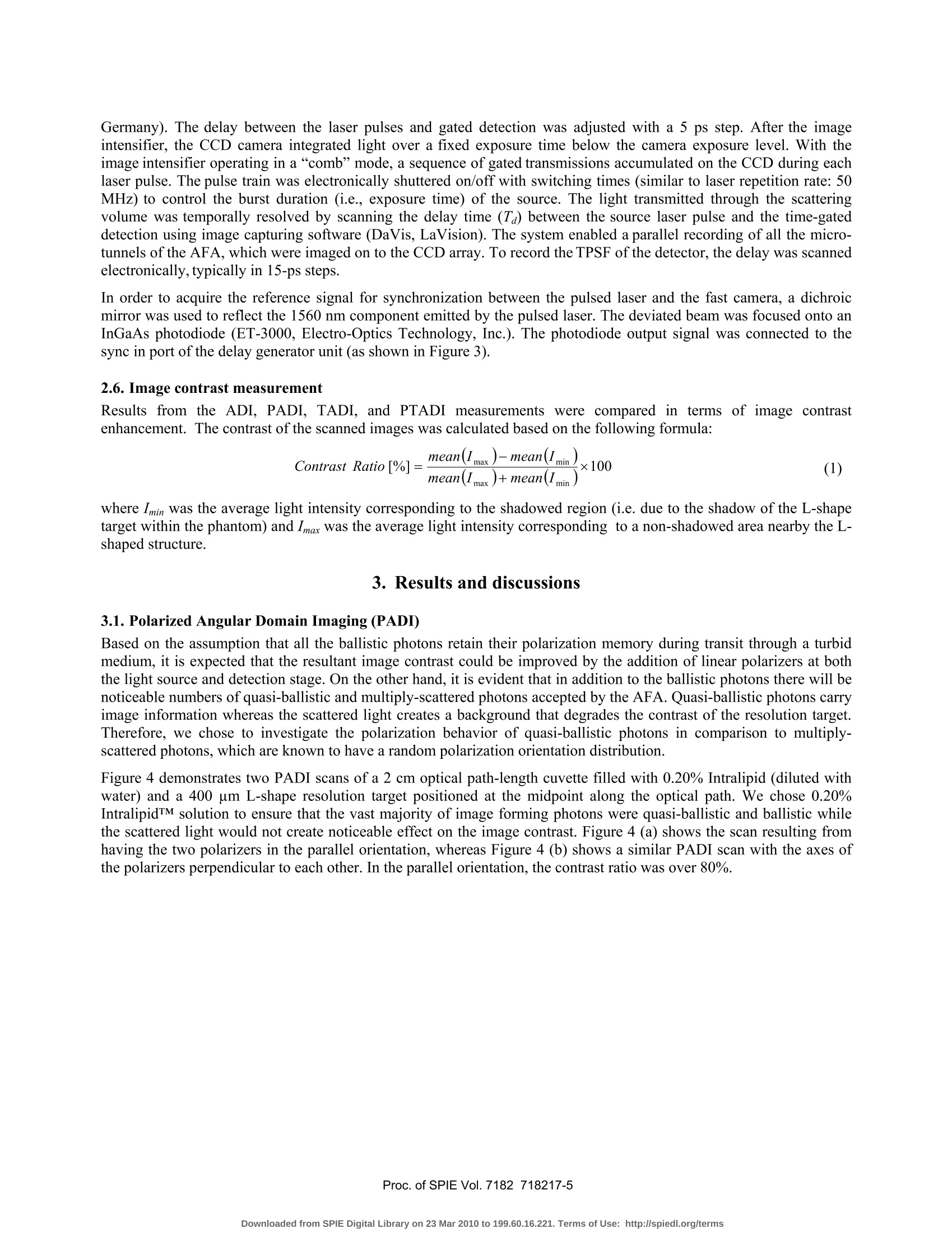
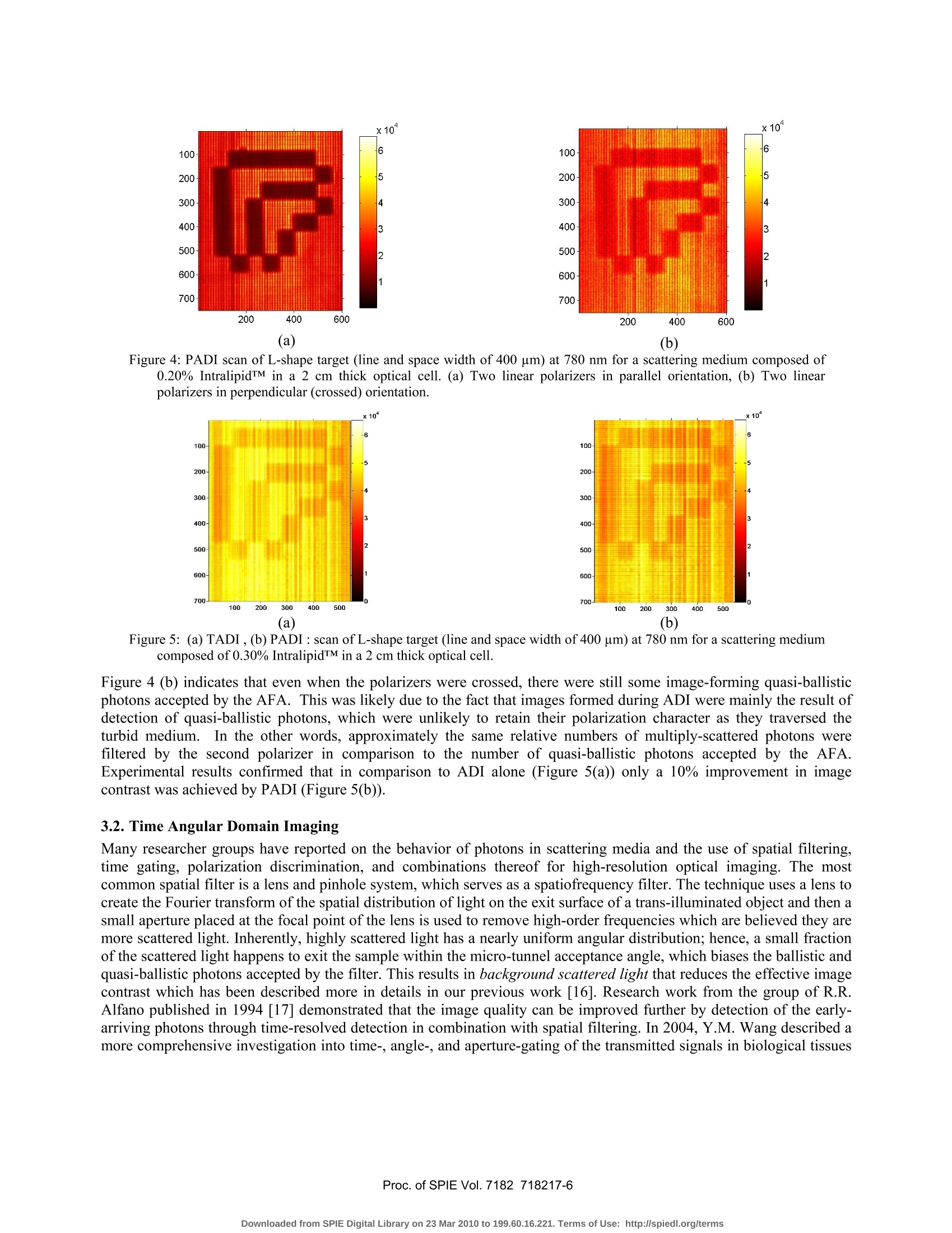
还剩8页未读,是否继续阅读?

产品配置单


北京欧兰科技发展有限公司为您提供《混浊介质中混浊介质角域成像(ADI)实验中光传播时间门控和偏振优选效应检测方案(CCD相机)》,该方案主要用于其他中混浊介质角域成像(ADI)实验中光传播时间门控和偏振优选效应检测,参考标准--,《混浊介质中混浊介质角域成像(ADI)实验中光传播时间门控和偏振优选效应检测方案(CCD相机)》用到的仪器有德国LaVision PIV/PLIF粒子成像测速场仪、PLIF平面激光诱导荧光火焰燃烧检测系统
推荐专场


相关方案
更多
该厂商其他方案
更多