


方案详情
文
The efficacy of dielectric barrier discharge (DBD) plasmas driven by repetitive nanosecond (NS) pulses for flow separation control is investigated experimentally on an airfoil leading edge up to Re=1x10⁶ (62 m/s). The NS pulse driven DBD plasma actuator (NS-DBD hereafter) transfers very little momentum to the neutral air, but generates compression waves similar to localized arc filament plasma actuators. Experimental results indicate that NS-DBD plasma performs as an active trip at pre-stall angles of attack and provides high amplitude perturbations that manipulate flow instabilities and generate coherent spanwise vortices at post-stall angles. These coherent structures entrain freestream momentum thereby reattaching the normally separated flow to the suction surface of the airfoil. Such devices which are believed to function through thermal effects could result in a significant improvement over AC-DBD plasmas that rely on momentum addition which limits their performance at high speeds.
方案详情

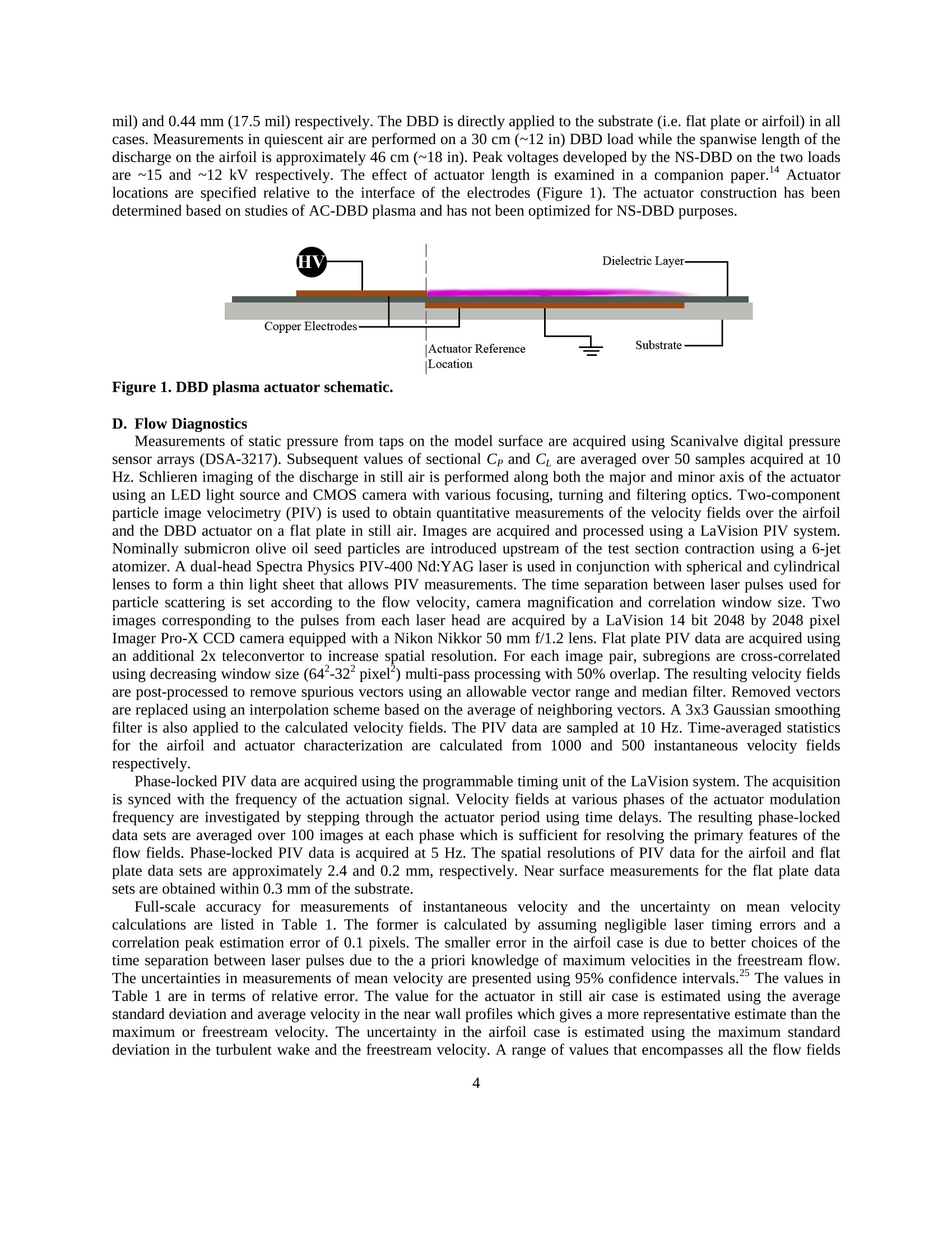
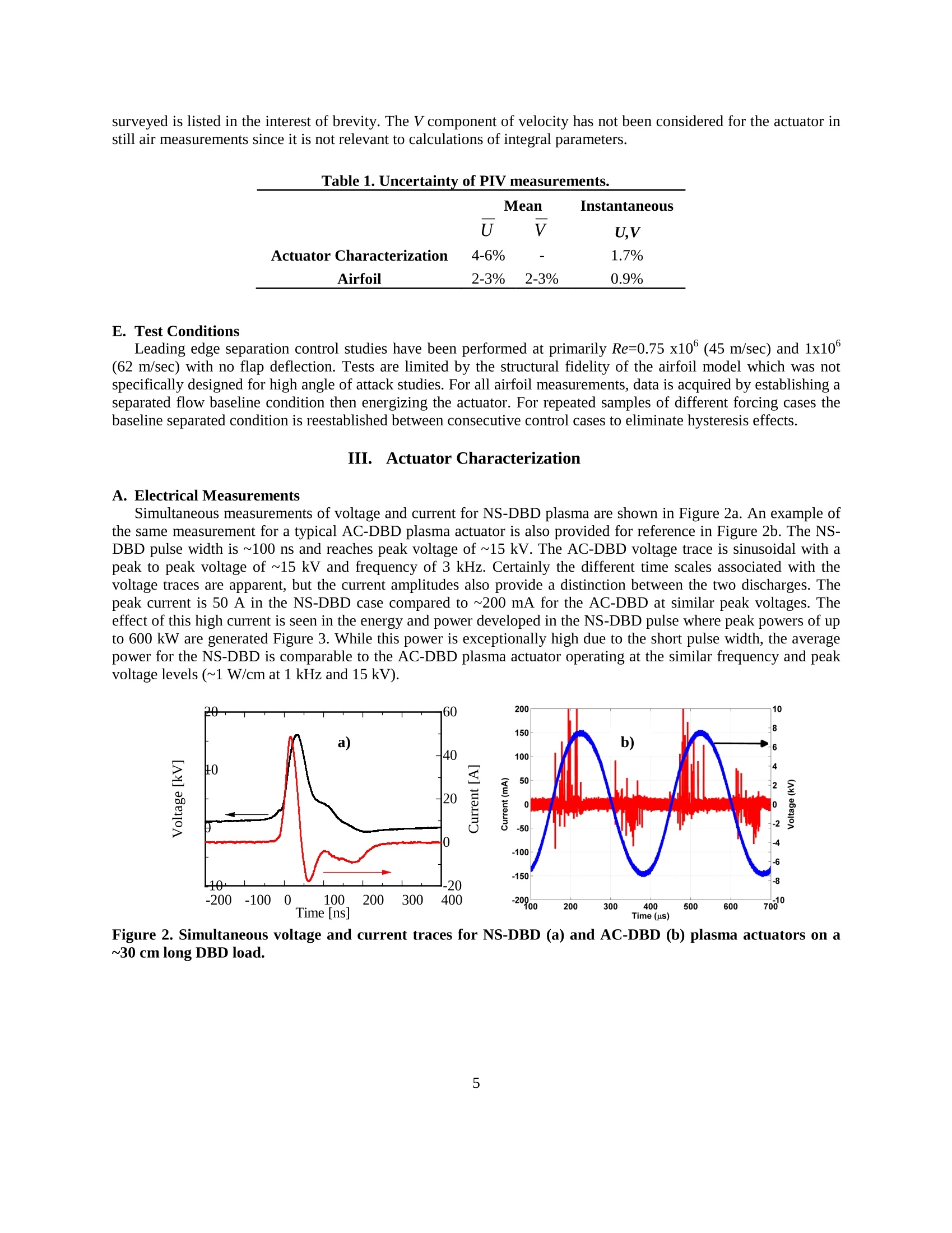
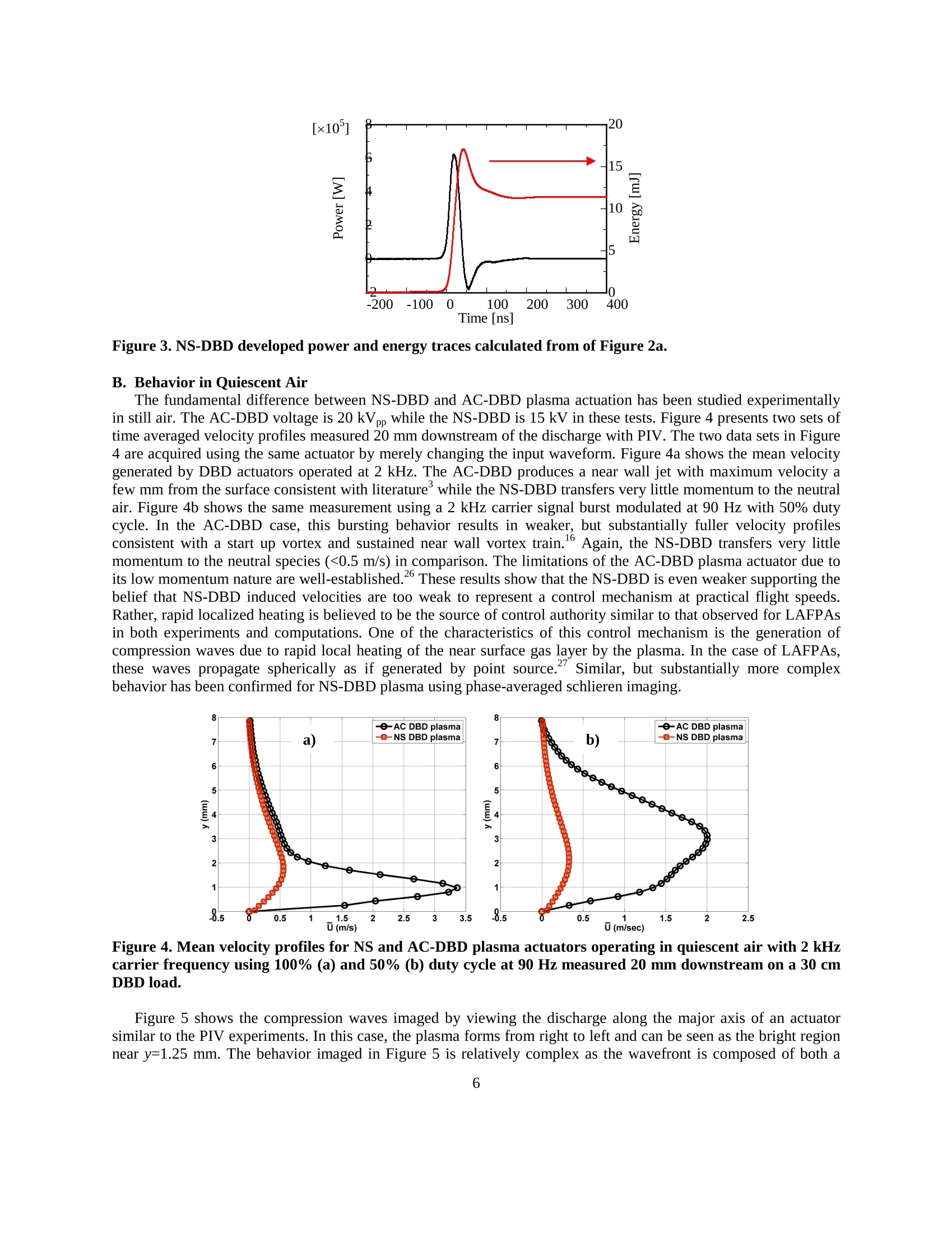
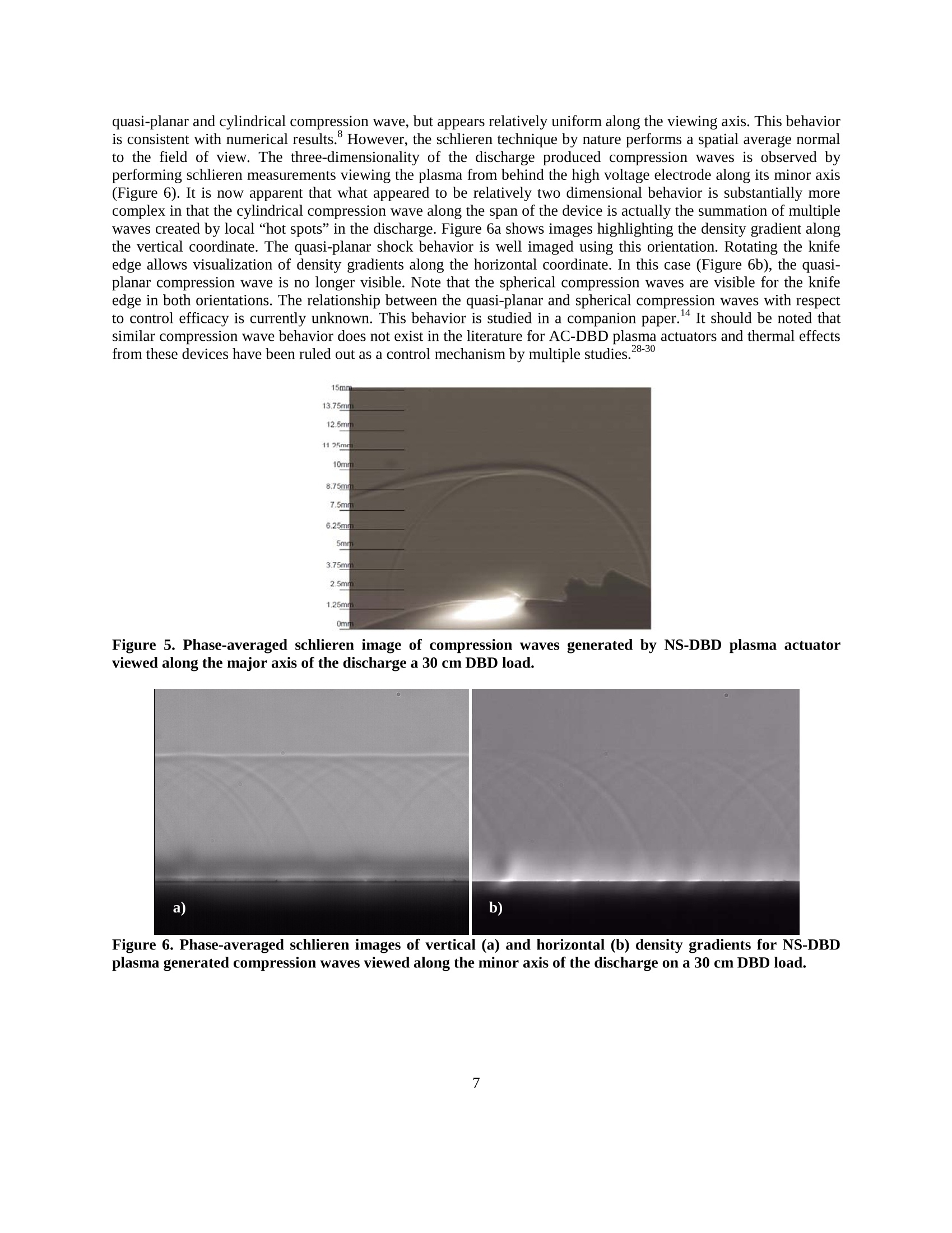
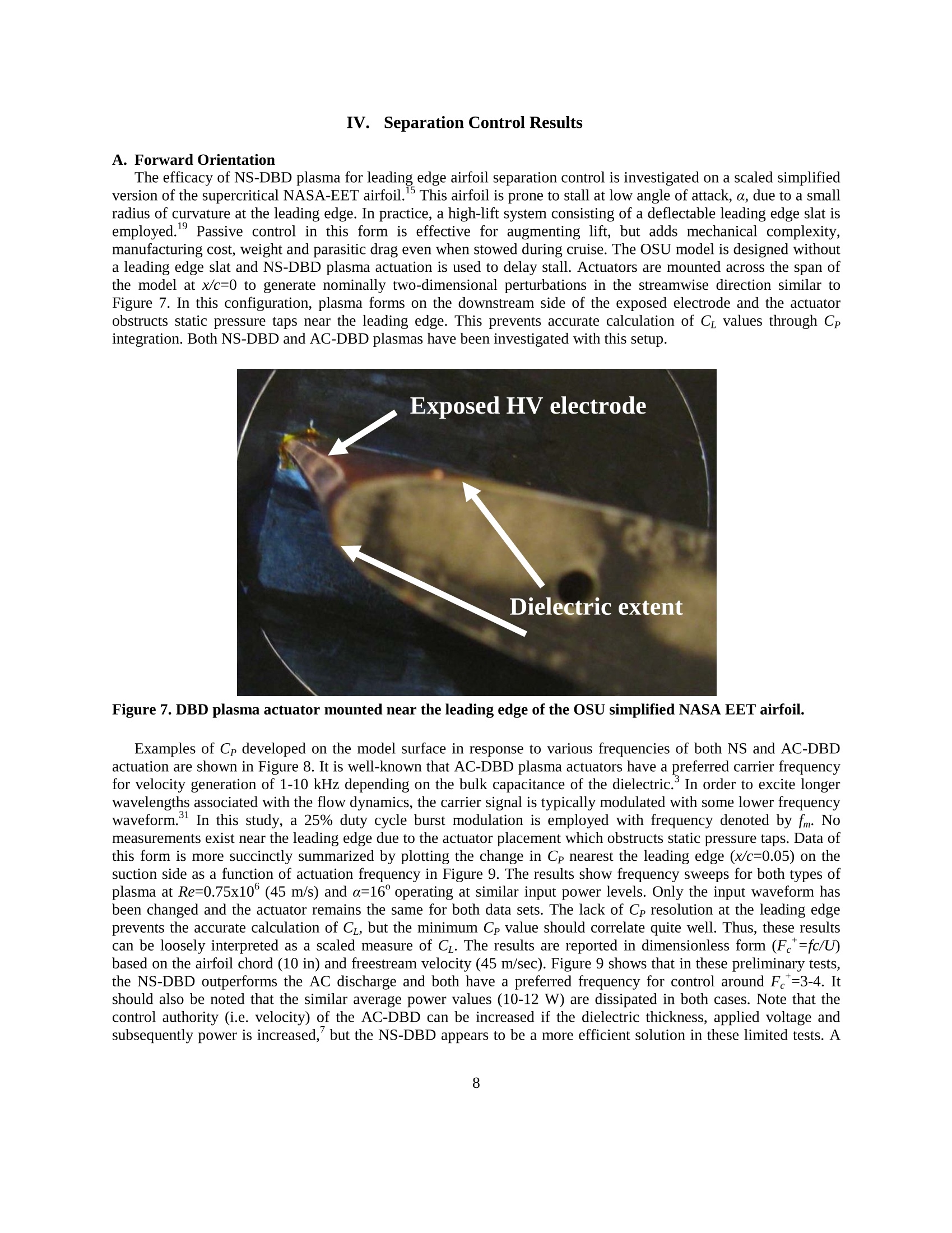
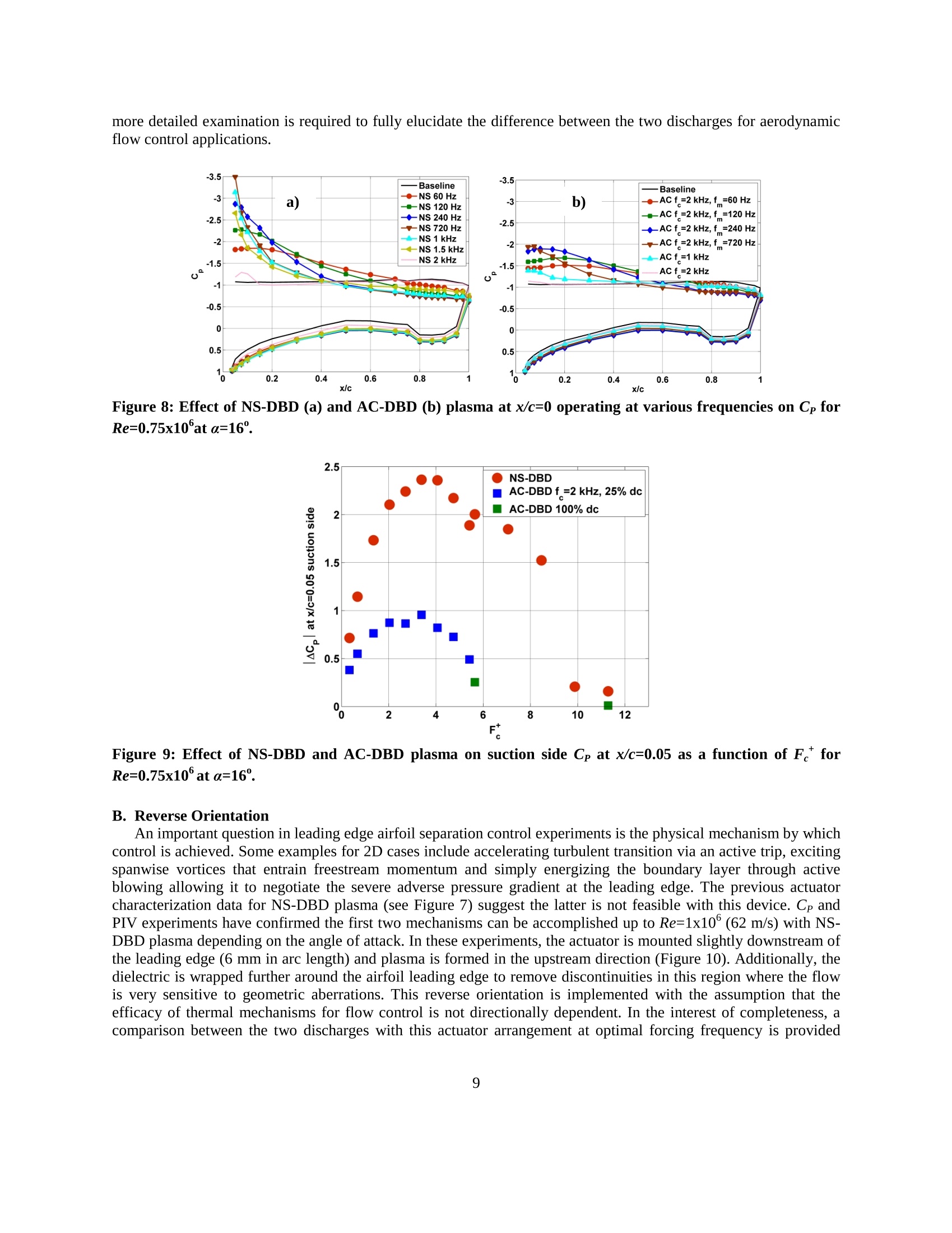
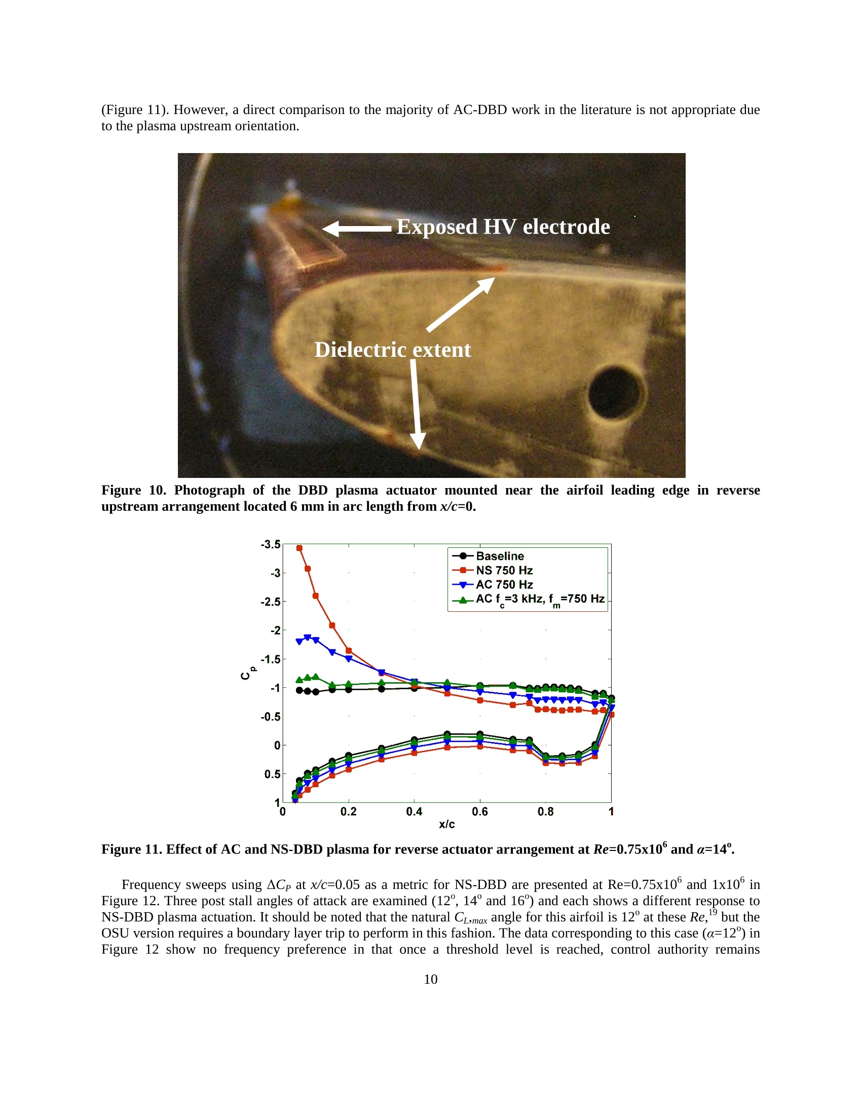
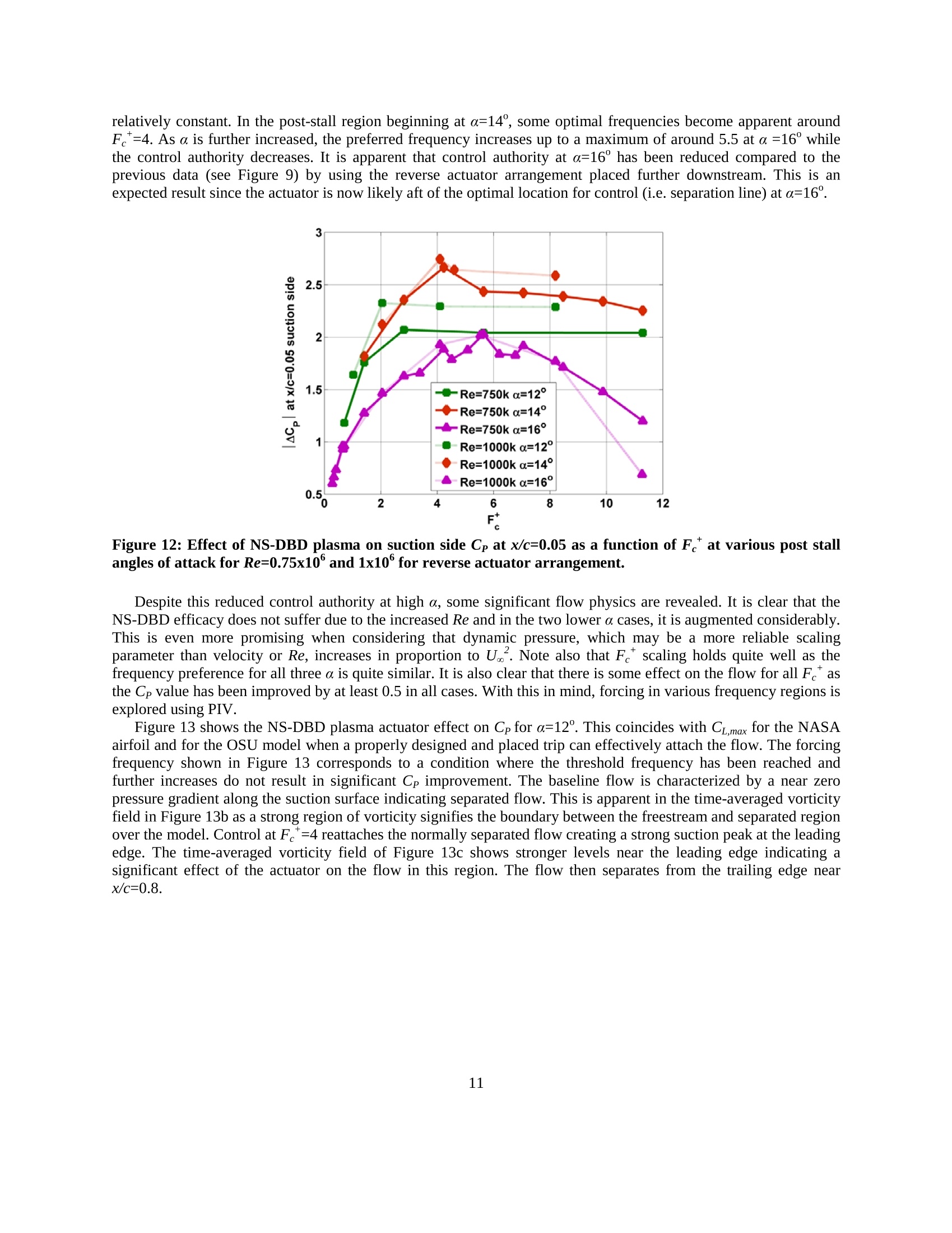
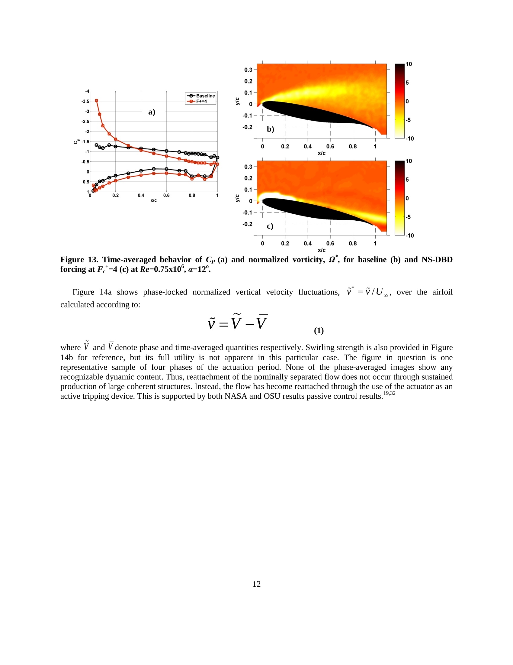
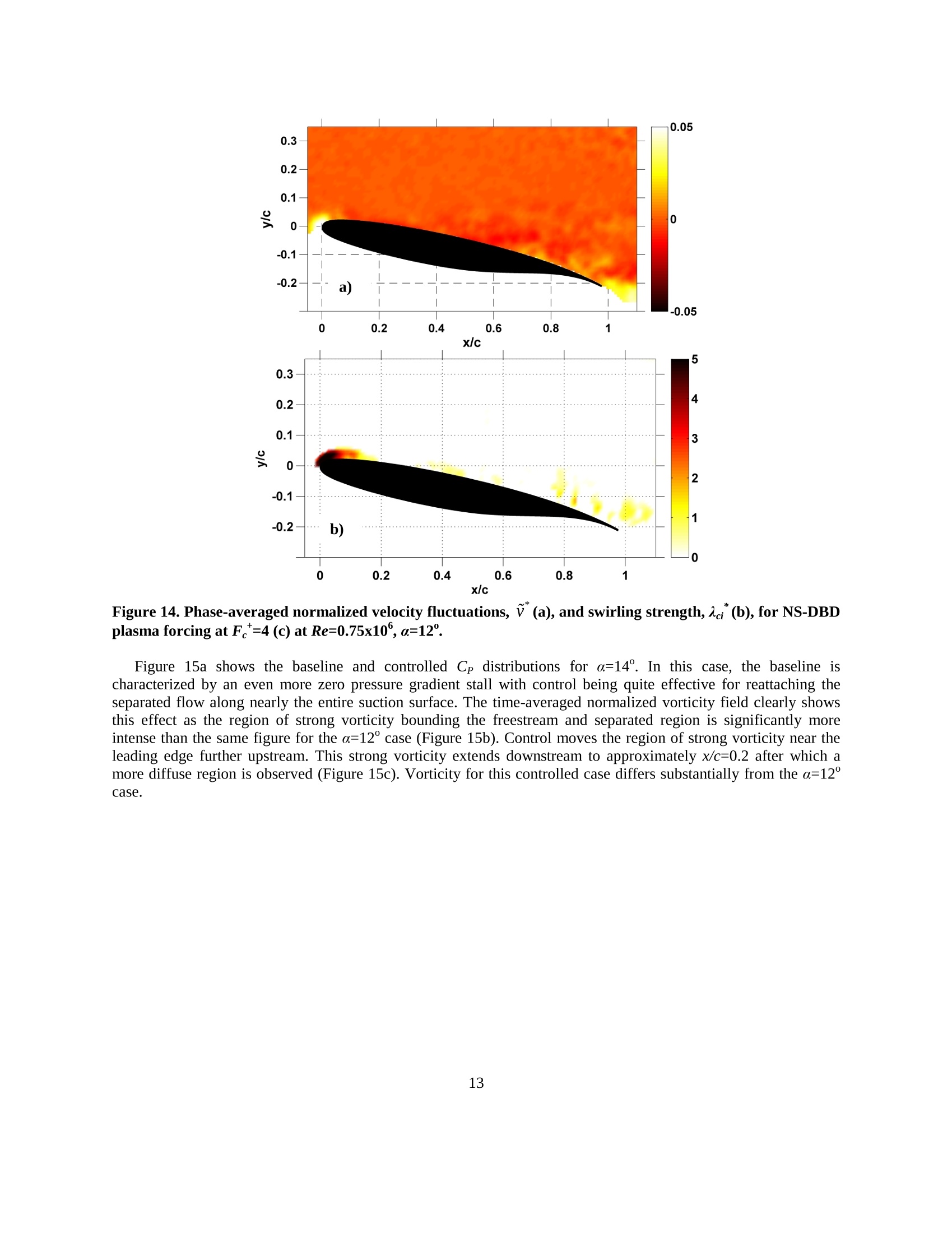
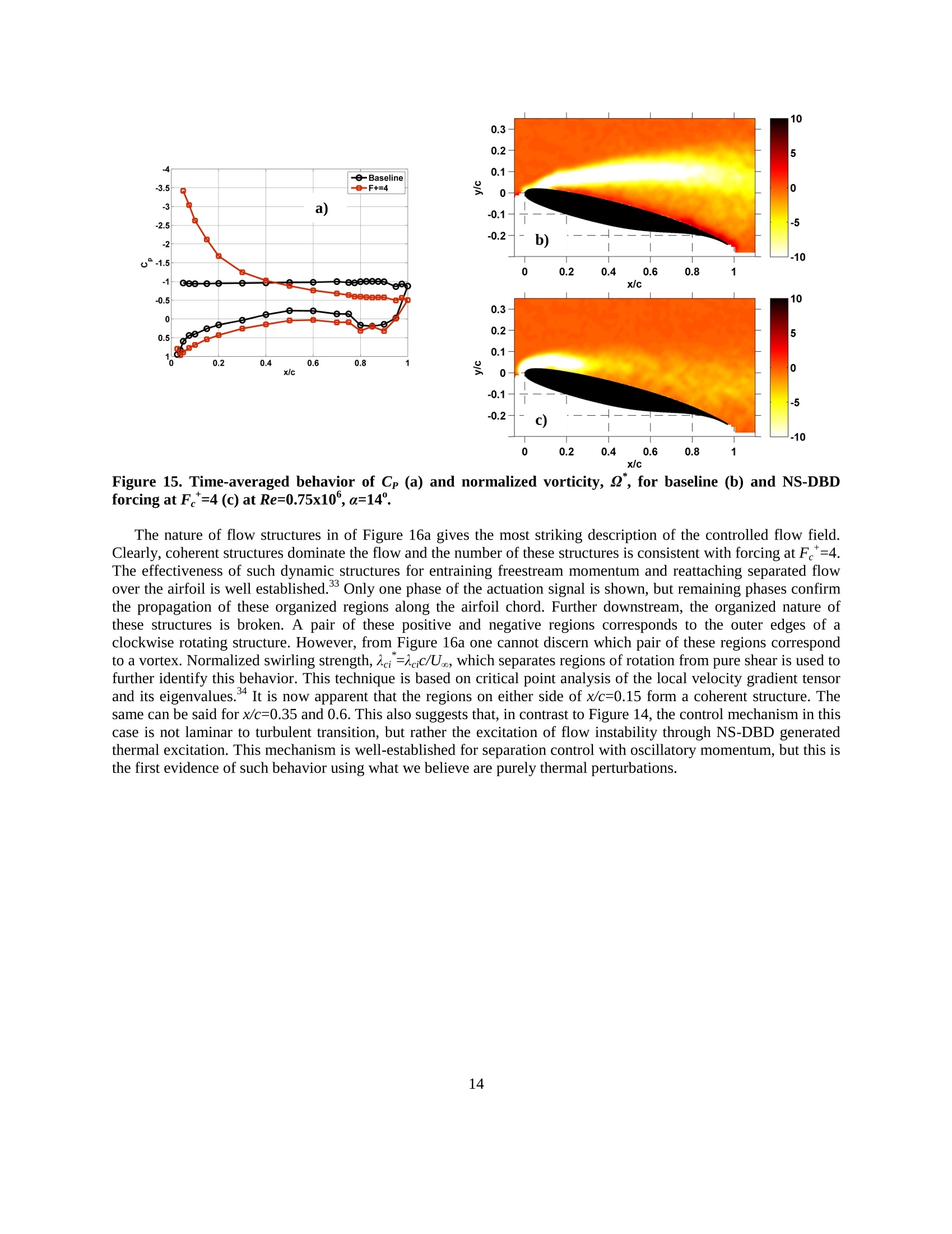
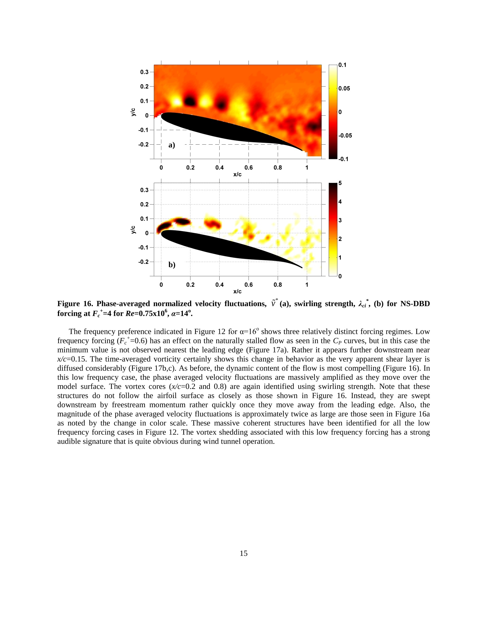
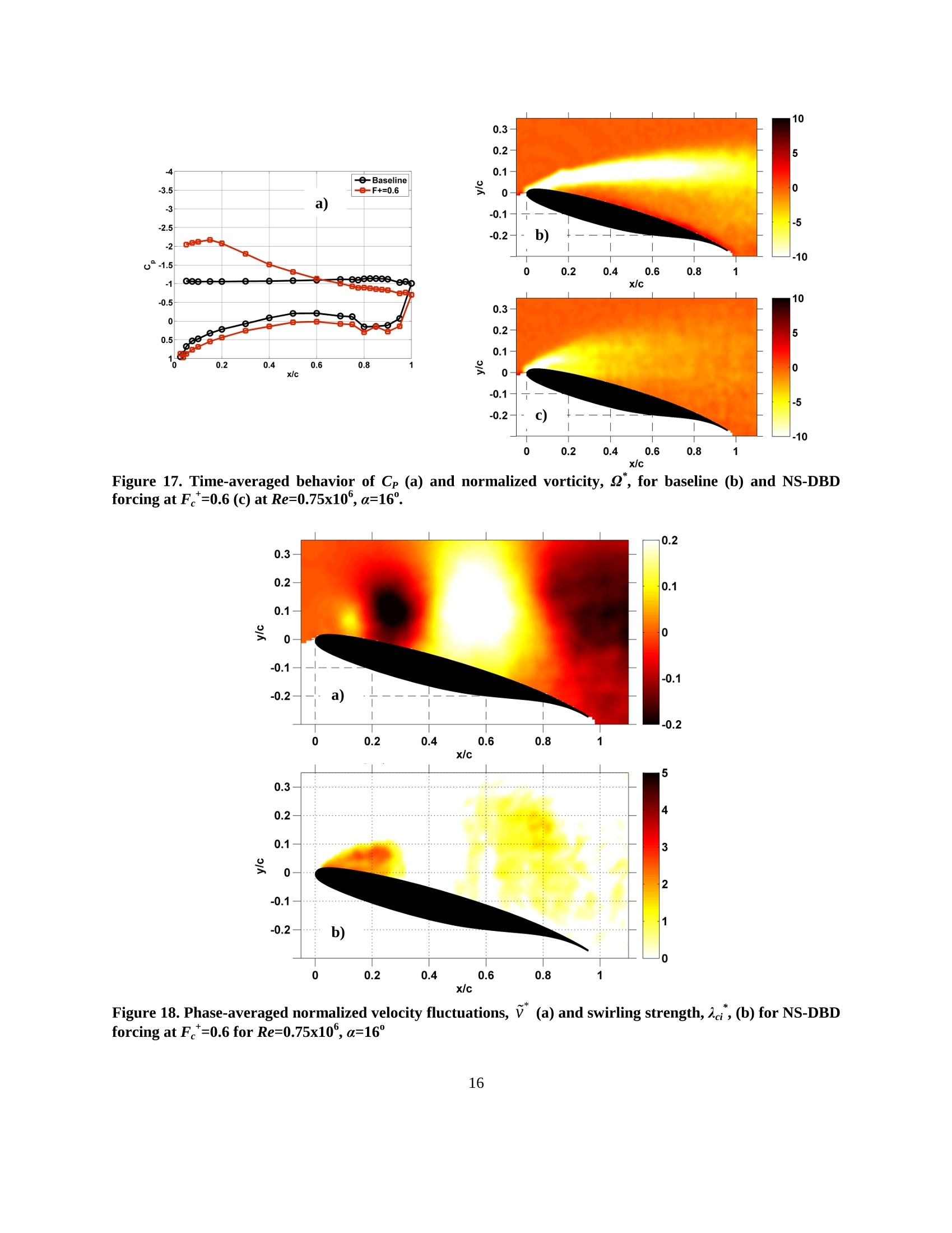
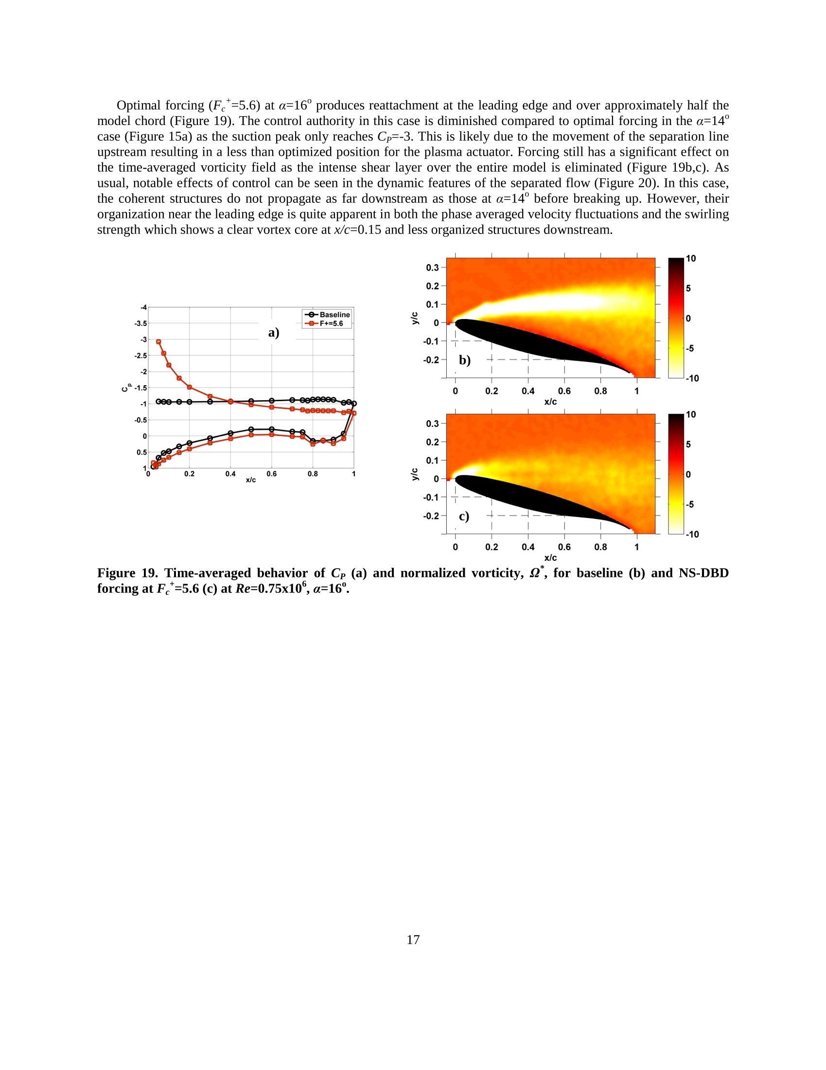
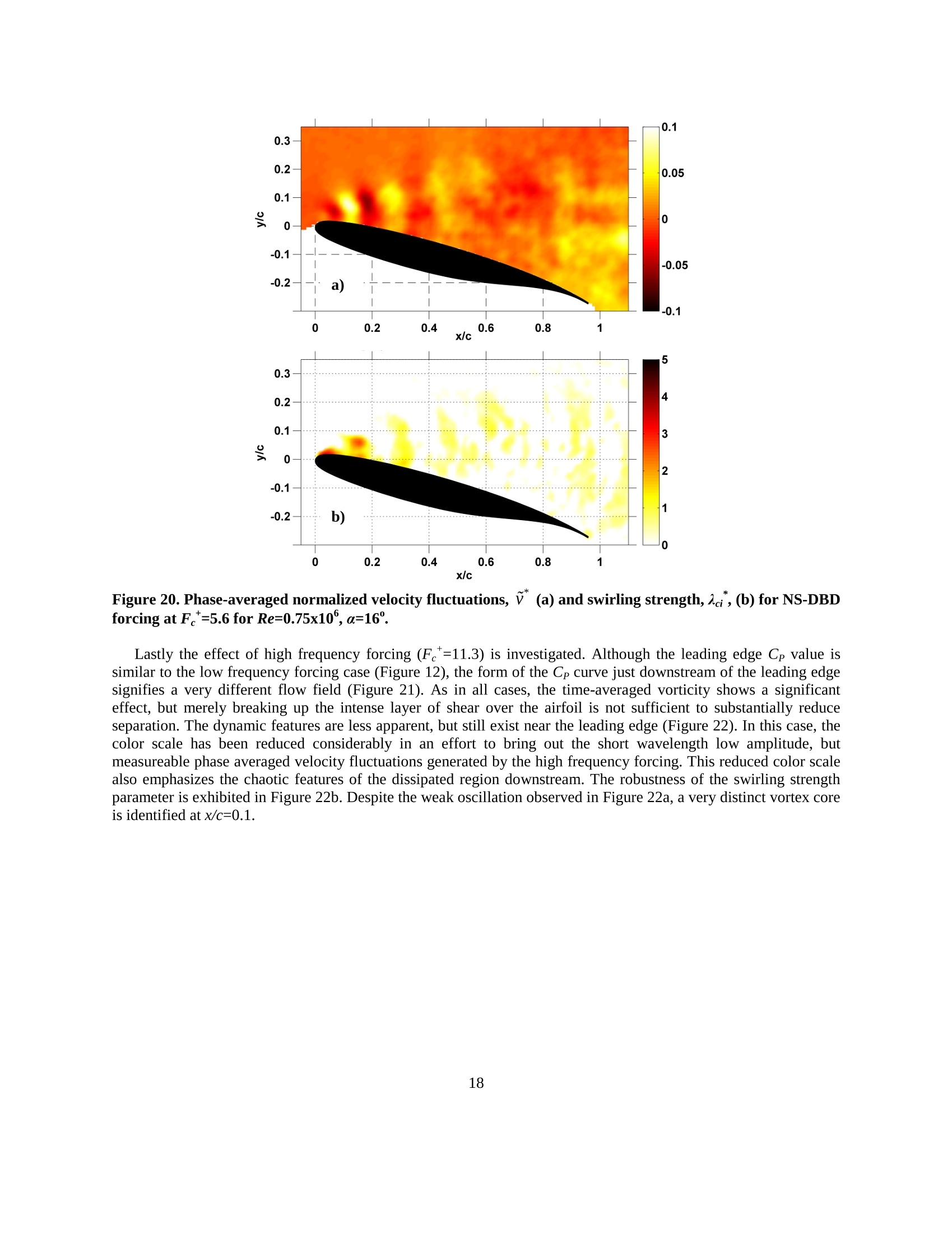
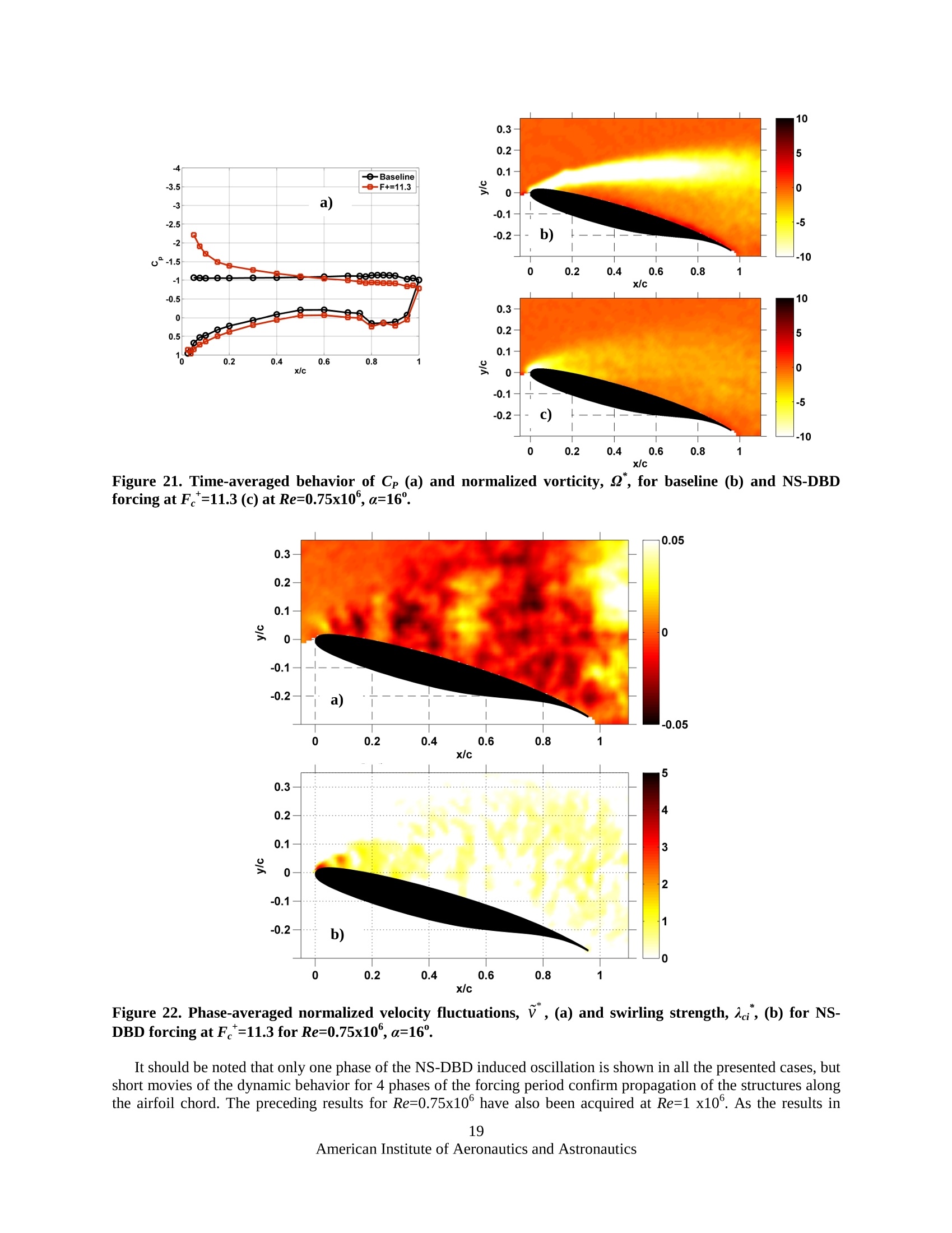
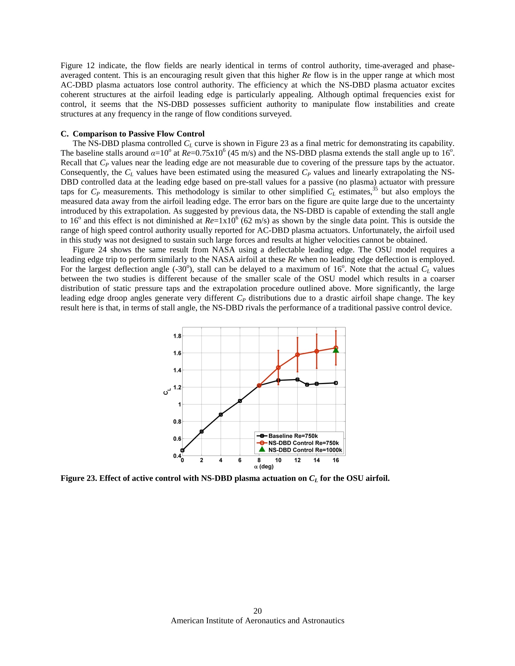
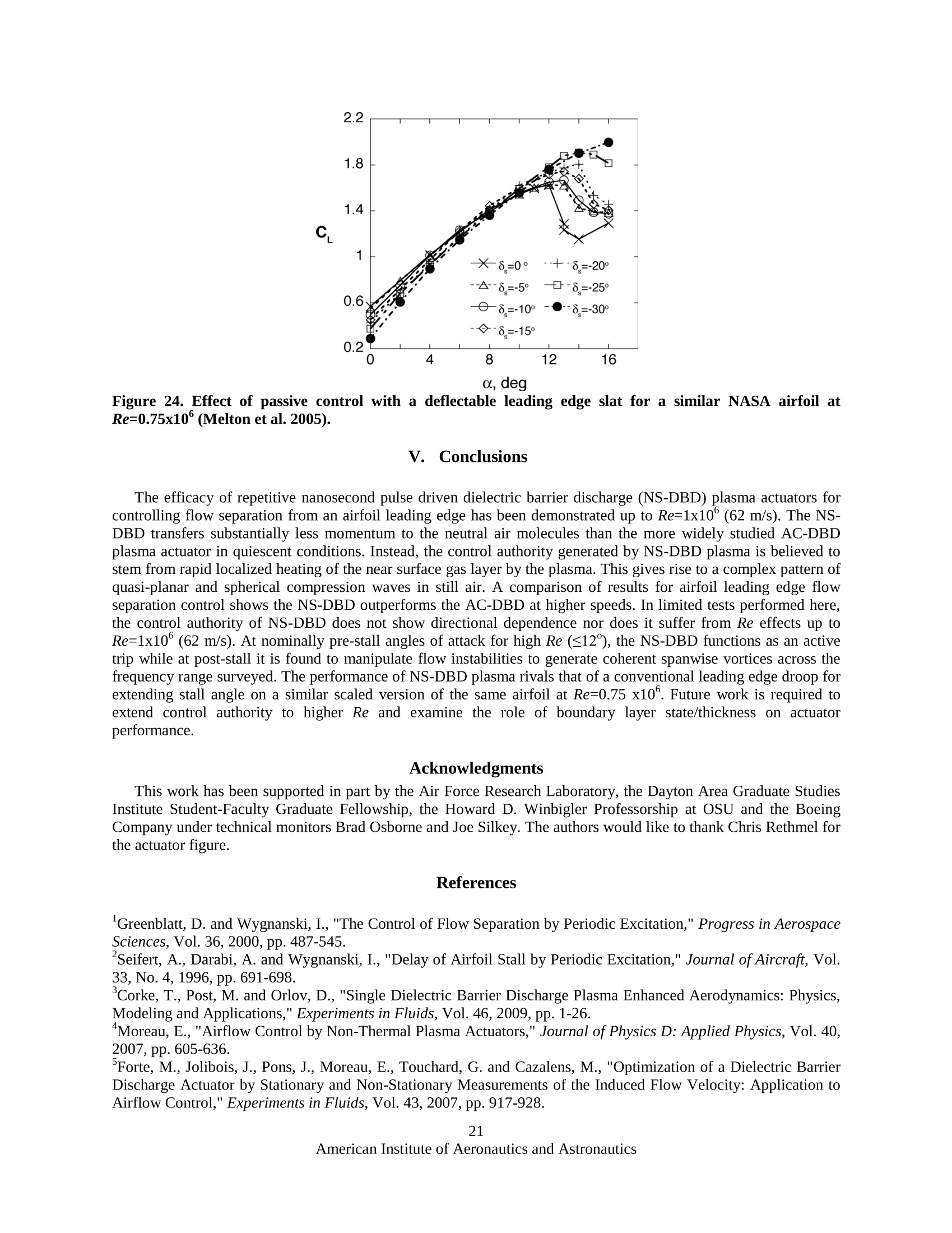
AIAA 2010-42565th Flow Control Conference28 June-1 July 2010, Chicago, Illinois High Lift Airfoil Leading Edge Separation Control withNanosecond Pulse Driven DBD Plasma Actuators Jesse Little, Keisuke Takashima , Munetake Nishihara, Igor Adamovich and Mo Samimy’ The Ohio State University, Gas Dynamics and Turbulence Laboratory, Columbus, OH, 43235 The efficacy of dielectric barrier discharge (DBD) plasmas drivene nt by repetitivenanosecond (NS) pulses for flow separation control is investigated experimentally on anairfoil leading edge up to Re=1x10°(62 m/s). The NS pulse driven DBD plasma actuator (NS-DBD hereafter) transfers very little momentum to the neutral air, but generates compressionwaves similar to localized arc filament plasma actuators. Experimental results indicate thatNS-DBD plasma performs as an active trip at pre-stall angles of attack and provides highamplitude perturbations that manipulate flow instabilities and generate coherent spanwisevortices at post-stall angles. These coherent structures entrain freestream momentumthereby reattaching the normally separated flow to the suction surface of the airfoil. Suchdevices which are believed to function through thermal effects could result in a significantimprovement over AC-DBD plasmas that rely on momentum addition which limits theirperformance at high speeds. Nomenclature Post-Doctoral Researcher, AIAA Member ( ‘Post-Doctoral Researcher, AIAA Member ) ( " Professor, AIAA Associate Fellow ) kkinematic viscosity =rnormalized swirling strength, Acic/U..civQ spanwise component of vorticity normalized spanwise vorticity, Qc/U.. I. Introduction 'Filow over solid bodies is retarded near the surface due to viscous effects which give rise to a boundary layer.Often the near wall fluid must also negotiate an adverse pressure gradient and/or geometric aberration. When themomentum in the boundary layer is insufficient to overcome these impediments, the boundary layer separates. Thisis marked by a thickening of the rotational region of fluid near the surface and an increase in the wall normalvelocity component. Boundary layer separation is synonymous with substantial energy losses and minimizing itsoccurrence is one of the primary design constraints for aerodynamic and hydrodynamic systems. A prime example of separation control is the airfoil at high angle of attack. This system produces maximum liftnear the angle at which separation occurs from the leading edge. Slight excursions to higher angles can result inunrecoverable stall. Transport aircraft often combat this using passive control devices in the form of segmentedleading edges that deploy during takeoff and landing to promote mixing between high momentum fluid on thepressure surface of the wing with low momentum fluid on the suction surface. These passive geometricmodifications are effective for augmenting lift, but create significant increases in mechanical complexity,manufacturing cost, weight and parasitic drag even when stowed during cruise. Active flow control in the form of localized periodic excitation has been used to impart global changes toseparated flow fields. This is accomplished by adding slots or orifices to the aerodynamic surface near potentialseparation locations. Periodic excitation, usually in the form of a velocity perturbation, is delivered through the slotsto manipulate natural flow instabilities in an effort to prevent or reattach separated flows. The optimal dimensionlessfrequency, F =fL/U., for controlling separation using periodic excitation is on the order of unity where f, L and U.are the forcing frequency, separation length scale and freestream velocity respectively. Generation of velocityperturbations can be accomplished through a variety of mechanisms, but often the use of piezoelectric,electromagnetic or electrostatic devices are employed. In all of these cases, an electromechanical driver creates theoscillatory flow used for excitation. These devices are controlled through electrical signals and, compared to passivecontrol, offer a significant reduction in weight, mechanical complexity and parasitic drag. Unfortunately, theypossess limited bandwidth and are subject to mechanical failure because the electromechanical driver is usuallyoperated at resonance to produce the large amplitude perturbations necessary at practical flight speeds. Even whenoperated in this fashion, it is difficult to meet amplitude requirements especially for cruise conditions. Flow control with plasma actuation is appealing because these devices are entirely surface mounted, lackmechanical parts and possess high bandwidth while requiring relatively low power. Dielectric Barrier Discharge(DBD) plasma actuators driven by AC waveforms (AC-DBD) are the most popular of these devices. They havebeen widely used for controlling flow separation, particularly on the leading edge of airfoils in relatively lowvelocity freestreams (~30 m/s). The control mechanism for AC-DBD plasma actuators arises from anelectrohydrodynamic (EHD) effect. Interaction between the charged species in the plasma and neutral particles nearthe surface generates a low speed (<10 m/s) near wall jet in quiescent air, thus limiting its application in practicalflight environments. Efforts to extend the AC-DBD control authority continue to be explored through optimizationof a single actuator, the use of multiple actuators and more novel arrangements like sliding discharges that rely onadditional DC bias voltages. The common goal in all these cases is to increase the velocity generated by thedevice. Early reports suggest DBD plasma actuators driven by a different type of waveform could be a superioralternative at high-speed. The construction of the device is analogous to the AC-DBD, but the discharge is driven byrepetitive nanosecond duration pulses. DBD plasma created using these waveforms has shown control authority forleading edge airfoil separation control up to Mach 0.74 in an isolated publication. This control authority is wellbeyond any reported results with AC-DBD plasma actuators on airfoils, but many questions such as the effect ofwind tunnel blockage and the underlying flow physics remain unanswered. It should be noted that such waveformshave also been used in combination with AC and DC bias voltage.9-10 The mechanism by which NS-DBD plasmas produce control is believed to be substantially different from theAC discharge. The NS-DBD produces very low if any velocity in the neutral species. Instead, a thermal effect (i.e.Joule heating) that generates a local compression wave is believed to provide the control mechanism. This scenario is well-established for localized arc filament plasma actuators (LAFPAs) that are effective for controlling highReynolds number and high-speed (subsonic/supersonic, cold/hot) jets in both experiments1-122and morecomputations. The main benefit for flow control with thermal perturbations seems to be their use at high speedswhere it is difficult for velocity based devices to reliably or efficiently produce sufficient momentum for controlauthority. This paper describes work on the development and application of nanosecond pulse driven DBD plasmaactuators for controlling flow separation from an airfoil leading edge. Control authority is demonstrated up toRe=1x10° (62 m/s) using static pressure and PIV measurements. These results show the NS-DBD can perform as anactive boundary layer trip or generate coherent spanwise vortices that are widely associated with controllingseparation in a variety of flow systems. A preliminary comparison to the more extensively studied AC-DBD showsthat the NS-DBD has superior performance at the airfoil leading edge for the surveyed conditions. Actuatorcharacterization is briefly described, but the reader is referred to a companion paper for more detail on this aspect. i.EExperimental Facility and Techniques A. Wind Tunnel Facility and Airfoil Model This study employs a closed, recirculating wind tunnel with an optically accessible 61 x 61 x 122 cm (2 x2 x 4ft’) test section. Air flow in the tunnel is continuously variable from 3-90 m/s (10-300 ft/s) with freestreamturbulence levels on the order of 0.25%.The tunnel is equipped with a heat exchanger that allows the freestreamoperating temperature to be maintained within 1°C of ambient. The airfoil is a simplified high-lift version of the NASA Energy Efficient Transport (EET) with chord length of25.4 cm (10 in) and span of 61 cm (2 ft). It was originally designed for studies of separation control over a deflectedflap at low angle of attack.16-17 The current work examines leading edge separation control at high angle of attackwith no flap deflection. It is constructed of a nylon compound (Duraform GF) and has been fabricated usingselective laser sintering (SLS) technology. Angle of attack settings are done manually using a protractor on the sidewall. 45 static pressure taps are located near the test section centerline. The airfoil model is mounted across the spanof the tunnel and supported by 12 inch diameter wall plugs on either side. Maximum blockage in the current study is~12% and occurs at 16° angle of attack. No blockage or wall corrections have been employed. Significant studies onactive flow control with zero net mass flux actuators have been completed for a similar simplified version. 8-23 B. Plasma Hardware Input signals for the AC-DBD plasma actuators are generated using a dSpace DSP 1103 board andcorresponding software. Signals generated by dSpace are used as inputs to a Powertron Model 1500S AC powersupply and step-up high voltage transformer. Amplified signals are sent to a low power (200 W) high voltage (0-20kVrms) transformer designed to operate in the frequency range of 1-5 kHz. Voltage measurements are acquired andmonitored at the secondary side of the high voltage transformer with a Tektronix P6015A probe. The powerdissipated by the actuator is calculated using charge-voltage measurements where a 47 nF capacitor is connected inseries with the covered ground electrode.4 The voltage across the capacitor is measured using a Tektronix P6111Bvoltage probe. The corresponding signals are monitored on a LeCroy Waverunner 6050A oscilloscope, but theactual power calculation is performed offline. High voltage nanosecond pulses are generated using an in-house constructed pulse generator. The pulserproduces ~15kV pulses at repetition rates up to 3 kHz. Pulse energies of ~17 mJ are delivered into the tested DBDload. A Tektronix AF6310 function generator provides input signals. A shunt resistor probe is employed for thecurrent measurements in this case. C. DBD Actuator Construction Actuators are composed of two copper tape electrodes separated by Kapton tape dielectric arranged in anasymmetric fashion (Figure 1). There is a slight overlap between the electrodes to encourage uniform plasmageneration. The covered ground electrode is 12.7 mm (Y inch) wide and the exposed high voltage electrode is 6.35mm (yin) wide. Both electrodes have thickness of 0.09 mm (3.5 mil). The dielectric barrier is composed of 3 layersof Kapton tape. Each layer has thickness of 0.09 mm (3.5 mil) and dielectric strength of 10 kV. Each layer ofKapton tape has a 0.04 mm (1.5 mil) layer of silicone adhesive such that the actual Kapton thickness for each tapelayer is only 0.05 mm (2 mil). The total thicknesses of the dielectric and the device as a whole are 0.27 mm (10.5 mil) and 0.44 mm (17.5 mil) respectively. The DBD is directly applied to the substrate (i.e. flat plate or airfoil) in allcases. Measurements in quiescent air are performed on a 30 cm (~12 in) DBD load while the spanwise length of thedischarge on the airfoil is approximately 46 cm (~18 in). Peak voltages developed by the NS-DBD on the two loadsare ~15 and ~12 kV respectively. The effect of actuator length is examined in a companion paper. Actuatorlocations are specified relative to the interface of the electrodes (Figure 1). The actuator construction has beendetermined based on studies of AC-DBD plasma and has not been optimized for NS-DBD purposes. Figure 1. DBD plasma actuator schematic. D. Flow Diagnostics Measurements of static pressure from taps on the model surface are acquired using Scanivalve digital pressuresensor arrays (DSA-3217). Subsequent values of sectional Cp and C are averaged over 50 samples acquired at 10Hz. Schlieren imaging of the discharge in still air is performed along both the major and minor axis of the actuatorusing an LED light source and CMOS camera with various focusing, turning and filtering optics. Two-componentparticle image velocimetry(PIV) is used to obtain quantitative measurements of the velocity fields over the airfoiland the DBD actuator on a flat plate in still air. Images are acquired and processed using a LaVision PIV system.Nominally submicron olive oil seed particles are introduced upstream of the test section contraction using a 6-jetatomizer. A dual-head Spectra Physics PIV-400 Nd:YAG laser is used in conjunction with spherical and cylindricallenses to form a thin light sheet that allows PIV measurements. The time separation between laser pulses used forparticle scattering is set according to the flow velocity, camera magnification and correlation window size. Twoimages corresponding to the pulses from each laser head are acquired by a LaVision 14 bit 2048 by 2048 pixelImager Pro-X CCD camera equipped with a Nikon Nikkor 50 mm f/1.2 lens. Flat plate PIV data are acquired usingan additional 2x teleconvertor to increase spatial resolution. For each image pair, subregions are cross-correlatedusing decreasing window size (642-32"pixel) multi-pass processing with 50% overlap. The resulting velocity fieldsare post-processed to remove spurious vectors using an allowable vector range and median filter. Removed vectorsare replaced using an interpolation scheme based on the average of neighboring vectors. A 3x3 Gaussian smoothingfilter is also applied to the calculated velocity fields. The PIV data are sampled at 10 Hz. Time-averaged statisticsfor the airfoil and actuator characterization are calculated from 1000 and 500 instantaneous velocity fieldsrespectively. Phase-locked PIV data are acquired using the programmable timing unit of the LaVision system. The acquisitionis synced with the frequency of the actuation signal. Velocity fields at various phases of the actuator modulationfrequency are investigated by stepping through the actuator period using time delays. The resulting phase-lockeddata sets are averaged over 100 images at each phase which is sufficient for resolving the primary features of theflow fields. Phase-locked PIV data is acquired at 5 Hz. The spatial resolutions of PIV data for the airfoil and flatplate data sets are approximately 2.4 and 0.2 mm, respectively. Near surface measurements for the flat plate datasets are obtained within 0.3 mm of the substrate. Full-scale accuracy for measurements of instantaneous velocity and the uncertainty on mean velocitycalculations are listed in Table 1. The former is calculated by assuming negligible laser timing errors and acorrelation peak estimation error of 0.1 pixels. The smaller error in the airfoil case is due to better choices of thetime separation between laser pulses due to the a priori knowledge of maximum velocities in the freestream flow.The uncertainties in measurements of mean velocity are presented using 95% confidence intervals.The values inTable 1 are in terms of relative error. The value for the actuator in still air case is estimated using the averagestandard deviation and average velocity in the near wall profiles which gives a more representative estimate than themaximum or freestream velocity. The uncertainty in the airfoil case is estimated using the maximum standarddeviation in the turbulent wake and the freestream velocity. A range of values that encompasses all the flow fields surveyed is listed in the interest of brevity. The V component of velocity has not been considered for the actuator instill air measurements since it is not relevant to calculations of integral parameters. Table 1. Uncertainty of PIV measurements. Mean Instantaneous u v U,V Actuator Characterization 4-6% 一 1.7% Airfoil 2-3% 2-3% 0.9% E. Test Conditions Leading edge separation control studies have been performed at primarily Re=0.75 x10°(45 m/sec) and 1x10°(62 m/sec) with no flap deflection. Tests are limited by the structural fidelity of the airfoil model which was notspecifically designed for high angle of attack studies. For all airfoil measurements, data is acquired by establishing aseparated flow baseline condition then energizing the actuator. For repeated samples of different forcing cases thebaseline separated condition is reestablished between consecutive control cases to eliminate hysteresis effects. III. Actuator Characterization A. Electrical Measurements Simultaneous measurements of voltage and current for NS-DBD plasma are shown in Figure 2a. An example ofthe same measurement for a typical AC-DBD plasma actuator is also provided for reference in Figure 2b. The NS-DBD pulse width is ~100 ns and reaches peak voltage of~15 kV. The AC-DBD voltage trace is sinusoidal with apeak to peak voltage of ~15 kV and frequency of 3 kHz. Certainly the different time scales associated with thevoltage traces are apparent, but the current amplitudes also provide a distinction between the two discharges. Thepeak current is 50 A in the NS-DBD case compared to ~200 mA for the AC-DBD at similar peak voltages. Theeffect of this high current is seen in the energy and power developed in the NS-DBD pulse where peak powers of upto 600 kW are generated Figure 3. While this power is exceptionally high due to the short pulse width, the averagepower for the NS-DBD is comparable to the AC-DBD plasma actuator operating at the similar frequency and peakvoltage levels (~1 W/cm at 1 kHz and 15kV). Figure 2. Simultaneous voltage and current traces for NS-DBD (a) and AC-DBD (b) plasma actuators on a~30 cm long DBD load. Figure3. NS-DBD developed power and energy traces calculated from of Figure 2a. B. Behavior in Quiescent Air The fundamental difference between NS-DBD and AC-DBD plasma actuation has been studied experimentallyin still air. The AC-DBD voltage is 20kVpp while the NS-DBD is 15 kV in these tests. Figure 4 presents two sets oftime averaged velocity profiles measured 20 mm downstream of the discharge with PIV. The two data sets in Figure4 are acquired using the same actuator by merely changing the input waveform. Figure 4a shows the mean velocitygenerated by DBD actuators operated at 2 kHz. The AC-DBD produces a near wall jet with maximum velocity afew mm from the surface consistent with literature’while the NS-DBD transfers very little momentum to the neutralair. Figure 4b shows the same measurement using a 2 kHz carrier signal burst modulated at 90 Hz with 50% dutycycle. In the AC-DBD case, this bursting behavior results in weaker, but substantially fuller velocity profilesconsistent with a start up vortex and sustained near wall vortex train. Again, the NS-DBD transfers very littlemomentum to the neutral species (<0.5 m/s) in comparison. The limitations of the AC-DBD plasma actuator due toits low momentum nature are well-established. These results show that the NS-DBD is even weaker supporting thebelief that NS-DBD induced velocities are too weak to represent a control mechanism at practical flight speeds.Rather, rapid localized heating is believed to be the source of control authority similar to that observed for LAFPAsin both experiments and computations. One of the characteristics of this control mechanism is the generation ofcompression waves due to rapid local heating of the near surface gas layer by the plasma. In the case of LAFPAs,these waves propagate spherically as if generated by point source. Similar, but substantially more complexbehavior has been confirmed for NS-DBD plasma using phase-averaged schlieren imaging. Figure 4. Mean velocity profiles for NS and AC-DBD plasma actuators operating in quiescent air with 2 kHzcarrier frequency using 100% (a) and 50% (b) duty cycle at 90 Hz measured 20 mm downstream on a 30 cmDBD load. Figure 5 shows the compression waves imaged by viewing the discharge along the major axis of an actuatorsimilar to the PIV experiments. In this case, the plasma forms from right to left and can be seen as the bright regionnear y=1.25 mm. The behavior imaged in Figure 5 is relatively complex as the wavefront is composed of both a quasi-planar and cylindrical compression wave, but appears relatively uniform along the viewing axis. This behavioris consistent with numerical results. However, the schlieren technique by nature performs a spatial average normalto the field of view. The three-dimensionality of the discharge produced compression waves is observed byperforming schlieren measurements viewing the plasma from behind the high voltage electrode along its minor axis(Figure 6). It is now apparent that what appeared to be relatively two dimensional behavior is substantially morecomplex in that the cylindrical compression wave along the span of the device is actually the summation of multiplewaves created by local“hot spots” in the discharge. Figure 6a shows images highlighting the density gradient alongthe vertical coordinate. The quasi-planar shock behavior is well imaged using this orientation. Rotating the knifeedge allows visualization of density gradients along the horizontal coordinate. In this case (Figure 6b), the quasi-planar compression wave is no longer visible. Note that the spherical compression waves are visible for the knifeedge in both orientations. The relationship between the quasi-planar and spherical compression waves with respectto control efficacy is currently unknown. This behavior is studied in a companion paper.It should be noted thatsimilar compression wave behavior does not exist in the literature for AC-DBD plasma actuators and thermal effectsfrom these devices have been ruled out as a control mechanism by multiple studies.28-30 Figure 5. Phase-averaged schlieren image of compression waves generated by NS-DBD plasma actuatorviewed along the major axis of the discharge a 30 cm DBD load. Figure 6. Phase-averaged schlieren images of vertical (a) and horizontal (b) density gradients for NS-DBDplasma generated compression waves viewed along the minor axis of the discharge on a 30 cm DBD load. IV. Separation Control Results A. Forward Orientation The efficacy of NS-DBD plasma for leading edge airfoil separation control is investigated on a scaled simplifiedversion of the supercritical NASA-EET airfoil.I This airfoil is prone to stall at low angle of attack, a, due to a smallradius of curvature at the leading edge. In practice, a high-lift system consisting of a deflectable leading edge slat isemployed. Passive control in this form is effective for augmenting lift, but adds mechanical complexity,manufacturing cost, weight and parasitic drag even when stowed during cruise. The OSU model is designed withouta leading edge slat and NS-DBD plasma actuation is used to delay stall. Actuators are mounted across the span ofthe model at x/c=0 to generate nominally two-dimensional perturbations in the streamwise direction similar toFigure 7. In this configuration, plasma forms on the downstream side of the exposed electrode and the actuatorobstructs static pressure taps near the leading edge. This prevents accurate calculation of Cz values through Cpintegration. Both NS-DBD and AC-DBD plasmas have been investigated with this setup. Figure 7. DBD plasma actuator mounted near the leading edge of the OSU simplified NASA EET airfoil. Examples of Cp developed on the model surface in response to various frequencies of both NS and AC-DBDactuation are shown in Figure 8. It is well-known that AC-DBD plasma actuators have a preferred carrier frequencyfor velocity generation of 1-10 kHz depending on the bulk capacitance of the dielectric. In order to excite longerwavelengths associated with the flow dynamics, the carrier signal is typically modulated with some lower frequencywaveform. In this study, a 25% duty cycle burst modulation is employed with frequency denoted by fm. Nomeasurements exist near the leading edge due to the actuator placement which obstructs static pressure taps. Data ofthis form is more succinctly summarized by plotting the change in Cp nearest the leading edge (x/c=0.05) on thesuction side as a function of actuation frequency in Figure 9. The results show frequency sweeps for both types ofplasma at Re=0.75x10°(45 m/s) and a=16° operating at similar input power levels. Only the input waveform hasbeen changed and the actuator remains the same for both data sets. The lack of Cp resolution at the leading edgeprevents the accurate calculation of Cz, but the minimum Cp value should correlate quite well. Thus, these resultscan be loosely interpreted as a scaled measure of C. The results are reported in dimensionless form (F=fc/U)based on the airfoil chord (10 in) and freestream velocity (45 m/sec). Figure 9 shows that in these preliminary tests,the NS-DBD outperforms the AC discharge and both have a preferred frequency for control around F=3-4. Itshould also be noted that the similar average power values (10-12 W) are dissipated in both cases. Note that thecontrol authority (i.e. velocity) of the AC-DBD can be increased if the dielectric thickness, applied voltage andsubsequently power is increased, but the NS-DBD appears to be a more efficient solution in these limited tests. A more detailed examination is required to fully elucidate the difference between the two discharges for aerodynamicflow control applications. Figure 8: Effect of NS-DBD (a) and AC-DBD (b) plasma at x/c=0 operating at various frequencies on Cp forRe=0.75x10°at a=16. Figure 9: Effect of NS-DBD and AC-DBD plasma on suction side Cp at x/c=0.05 as a function of FeforRe=0.75x10°at a=16°. B. Reverse Orientation An important question in leading edge airfoil separation control experiments is the physical mechanism by whichcontrol is achieved. Some examples for 2D cases include accelerating turbulent transition via an active trip, excitingspanwise vortices that entrain freestream momentum and simply energizing the boundary layer through activeblowing allowing it to negotiate the severe adverse pressure gradient at the leading edge. The previous actuatorcharacterization data for NS-DBD plasma (see Figure 7) suggest the latter is not feasible with this device. Cp andPIV experiments have confirmed the first two mechanisms can be accomplished up to Re=1x10° (62 m/s) with NS-DBD plasma depending on the angle of attack. In these experiments, the actuator is mounted slightly downstream ofthe leading edge (6 mm in arc length) and plasma is formed in the upstream direction (Figure 10). Additionally, thedielectric is wrapped further around the airfoil leading edge to remove discontinuities in this region where the flowis very sensitive to geometric aberrations. This reverse orientation is implemented with the assumption that theefficacy of thermal mechanisms for flow control is not directionally dependent. In the interest of completeness, acomparison between the two discharges with this actuator arrangement at optimal forcing frequency is provided (Figure 11). However, a direct comparison to the majority of AC-DBD work in the literature is not appropriate dueto the plasma upstream orientation. Figure 10. Photograph of the DBD plasma actuator mounted near the airfoil leading edge in reverseupstream arrangement located 6 mm in arc length from x/c=0. Figure 11. Effect of AC and NS-DBD plasma for reverse actuator arrangement at Re=0.75x10°and a=14". Frequency sweeps using ACp at x/c=0.05 as a metric for NS-DBD are presented at Re=0.75x10° and 1x10° inFigure 12. Three post stall angles of attack are examined (12°, 14° and 16°) and each shows a different response toNS-DBD plasma actuation. It should be noted that the natural Cumax angle for this airfoil is 12° at these Re,but theOSU version requires a boundary layer trip to perform in this fashion. The data corresponding to this case (a=12°) inFigure 12 show no frequency preference in that once a threshold level is reached, control authority remains relatively constant. In the post-stall region beginning at a=14, some optimal frequencies become apparent aroundF=4. As a is further increased, the preferred frequency increases up to a maximum of around 5.5 at a=16° whilethe control authority decreases. It is apparent that control authority at a=16° has been reduced compared to theprevious data (see Figure 9) by using the reverse actuator arrangement placed further downstream. This is anexpected result since the actuator is now likely aft of the optimal location for contro (i.e. separation line) at a=16°. Figure 12: Effect of NS-DBD plasma on suction side Cp at x/c=0.05 as a function of Fat various post stallangles of attack for Re=0.75x10° and 1x10° for reverse actuator arrangement. Despite this reduced control authority at high a, some significant flow physics are revealed. It is clear that theNS-DBD efficacy does not suffer due to the increased Re and in the two lower a cases, it is augmented considerably.This is even more promising when considering that dynamic pressure, which may be a more reliable scalingparameter than velocity or Re, increases in proportion to U.Note also that Fe scaling holds quite well as thefrequency preference for all three a is quite similar. It is also clear that there is some effect on the flow for all Feasthe Cp value has been improved by at least 0.5 in all cases. With this in mind, forcing in various frequency regions isexplored using PIV. Figure 13 shows the NS-DBD plasma actuator effect on Cp for a=12°. This coincides with CL,max for the NASAairfoil and for the OSU model when a properly designed and placed trip can effectively attach the flow. The forcingfrequency shown in Figure 13 corresponds to a condition where the threshold frequency has been reached andfurther increases do not result in significant Cp improvement. The baseline flow is characterized by a near zeropressure gradient along the suction surface indicating separated flow.This is apparent in the time-averaged vorticityfield in Figure 13b as a strong region of vorticity signifies the boundary between the freestream and separated regionover the model. Control at F*=4 reattaches the normally separated flow creating a strong suction peak at the leadingedge. The time-averaged vorticity field of Figure 13c shows stronger levels near the leading edge indicating asignificant effect of the actuator on the flow in this region. The flow then separates from the trailing edge nearx/c=0.8. Figure 13. Time-averaged behavior ofCp (a) and normalized vorticity,", for baseline (b) and NS-DBDforcing at F*=4 (c)at Re=0.75x10,a=12. Figure 14a shows phase-locked normalized vertical velocity fluctuations,S,v=/U, over the airfoilcalculated according to: where V and denote phase and time-averaged quantities respectively. Swirling strength is also provided in Figure14b for reference, but its full utility is not apparent in this particular case. The figure in question is onerepresentative sample of four phases of the actuation period. None of the phase-averaged images show anyrecognizable dynamic content. Thus, reattachment of the nominally separated flow does not occur through sustainedproduction of large coherent structures. Instead,the flow has become reattached through the use of the actuator as anactive tripping device. This is supported by both NASA and OSU results passive control results. 19,32 Figure 14. Phase-averaged normalized velocity fluctuations, V (a), and swirling strength, Aci(b), for NS-DBDplasma forcing at Fe*=4 (C) at Re=0.75x10°,a=12°. Figure 15a shows the baseline and controlled Cp distributions for a=14°. In this case, the baseline ischaracterized by an even more zero pressure gradient stall with control being quite effective for reattaching theseparated flow along nearly the entire suction surface. The time-averaged normalized vorticity field clearly showsthis effect as the region of strong vorticity bounding the freestream and separated region is significantly moreintense than the same figure for the a=12°case (Figure 15b). Control moves the region of strong vorticity near theleading edge further upstream. This strong vorticity extends downstream to approximately x/c=0.2 after which amore diffuse region is observed (Figure 15c). Vorticity for this controlled case differs substantially from the α=12°case. 10 Figure 15. Time-averaged behavior of Cp (a) and normalized vorticity,2, for baseline (b) and NS-DBDforcing at F*=4 (c) at Re=0.75x10,a=14°. The nature of flow structures in of Figure 16a gives the most striking description of the controlled flow field.Clearly, coherent structures dominate the flow and the number of these structures is consistent with forcing at F*=4.The effectiveness of such dynamic structures for entraining freestream momentum and reattaching separated flowover the airfoil is well established. Only one phase of the actuation signal is shown, but remaining phases confirmthe propagation of these organized regions along the airfoil chord. Further downstream, the organized nature ofthese structures is broken. A pair of these positive and negative regions corresponds to the outer edges of aclockwise rotating structure. However, from Figure 16a one cannot discern which pair of these regions correspondto a vortex. Normalized swirling strength, Aci=A;c/U., which separates regions of rotation from pure shear is used tofurther identify this behavior. This technique is based on critical point analysis of the local velocity gradient tensorand its eigenvalues. It is now apparent that the regions on either side of x/c=0.15 form a coherent structure. Thesame can be said for x/c=0.35 and 0.6. This also suggests that, in contrast to Figure 14, the control mechanism in thiscase is not laminar to turbulent transition, but rather the excitation of flow instability through NS-DBD generatedthermal excitation. This mechanism is well-established for separation control with oscillatory momentum, but this isthe first evidence of such behavior using what we believe are purely thermal perturbations. Figure 16. Phase-averaged normalized velocity fluctuations, v (a), swirling strength, Aci, (b) for NS-DBDforcing at F *=4 for Re=0.75x10,a=14. The frequency preference indicated in Figure 12 for a=16° shows three relatively distinct forcing regimes. Lowfrequency forcing (Fe=0.6) has an effect on the naturally stalled flow as seen in the Cp curves, but in this case theminimum value is not observed nearest the leading edge (Figure 17a). Rather it appears further downstream nearx/c=0.15. The time-averaged vorticity certainly shows this change in behavior as the very apparent shear layer isdiffused considerably (Figure 17b,c). As before, the dynamic content of the flow is most compelling (Figure 16). Inthis low frequency case, the phase averaged velocity fluctuations are massively amplified as they move over themodel surface. The vortex cores (x/c=0.2 and 0.8) are again identified using swirling strength. Note that thesestructures do not follow the airfoil surface as closely as those shown in Figure 16. Instead, they are sweptdownstream by freestream momentum rather quickly once they move away from the leading edge. Also, themagnitude of the phase averaged velocity fluctuations is approximately twice as large are those seen in Figure 16aas noted by the change in color scale. These massive coherent structures have been identified for all the lowfrequency forcing cases in Figure 12. The vortex shedding associated with this low frequency forcing has a strongaudible signature that is quite obvious during wind tunnel operation. Figure 17. Time-averaged behavior of Cp (a) and normalized vorticity,2, for baseline (b) and NS-DBDforcing at F*=0.6 (C) at Re=0.75x10°,a=16°. Figure 18. Phase-averaged normalized velocity fluctuations, v(a) and swirling strength, Aci, (b) for NS-DBDforcing at F*=0.6 for Re=0.75x10,a=16° Optimal forcing (Fc*=5.6) at a=16° produces reattachment at the leading edge and over approximately half themodel chord (Figure 19). The control authority in this case is diminished compared to optimal forcing in the α=14°case (Figure 15a) as the suction peak only reaches Cp=-3. This is likely due to the movement of the separation lineupstream resulting in a less than optimized position for the plasma actuator. Forcing still has a significant effect onthe time-averaged vorticity field as the intense shear layer over the entire model is eliminated (Figure 19b,c). Asusual, notable effects of control can be seen in the dynamic features of the separated flow (Figure 20). In this case,the coherent structures do not propagate as far downstream as those at a=14 before breaking up. However, theirorganization near the leading edge is quite apparent in both the phase averaged velocity fluctuations and the swirlingstrength which shows a clear vortex core at x/c=0.15 and less organized structures downstream. x/c Figure 19. Time-averaged behavior of Cp (a) and normalized vorticity, , for baseline (b) and NS-DBDforcing at F*=5.6 (c) at Re=0.75x10,a=16°. Figure 20. Phase-averaged normalized velocity fluctuations, v (a) and swirling strength, Aci, (b) for NS-DBDforcing at Fe*=5.6 for Re=0.75x10,a=16°. Lastly the effect of high frequency forcing (Fe =11.3) is investigated. Although the leading edge Cp value issimilar to the low frequency forcing case (Figure 12), the form of the Cp curve just downstream of the leading edgesignifies a very different flow field (Figure 21). As in all cases, the time-averaged vorticity shows a significanteffect, but merely breaking up the intense layer of shear over the airfoil is not sufficient to substantially reduceseparation. The dynamic features are less apparent, but still exist near the leading edge (Figure 22). In this case, thecolor scale has been reduced considerably in an effort to bring out the short wavelength low amplitude, butmeasureable phase averaged velocity fluctuations generated by the high frequency forcing. This reduced color scalealso emphasizes the chaotic features of the dissipated region downstream. The robustness of the swirling strengthparameter is exhibited in Figure 22b. Despite the weak oscillation observed in Figure 22a, a very distinct vortex coreis identified at x/c=0.1. Figure 21. Time-averaged behavior of Cp(a) and normalized vorticity, , for baseline (b) and NS-DBDforcing at F*=11.3(c) at Re=0.75x10°,a=16%. Figure 22. Phase-averaged normalized velocity fluctuations, V, (a) and swirling strength, Aci, (b) for NS-DBD forcing at F*=11.3 for Re=0.75x10°,a=16. It should be noted that only one phase of the NS-DBD induced oscillation is shown in all the presented cases, butshort movies of the dynamic behavior for 4 phases of the forcing period confirm propagation of the structures alongthe airfoil chord. The preceding results for Re=0.75x10° have also been acquired at Re=1 x10. As the results in Figure 12 indicate, the flow fields are nearly identical in terms of control authority, time-averaged and phase-averaged content. This is an encouraging result given that this higher Re flow is in the upper range at which mostAC-DBD plasma actuators lose control authority. The efficiency at which the NS-DBD plasma actuator excitescoherent structures at the airfoil leading edge is particularly appealing. Although optimal frequencies exist forcontrol, it seems that the NS-DBD possesses sufficient authority to manipulate flow instabilities and createstructures at any frequency in the range of flow conditions surveyed. C. Comparison to Passive Flow Control The NS-DBD plasma controlled C curve is shown in Figure 23 as a final metric for demonstrating its capability.The baseline stalls around a=10° at Re=0.75x10° (45 m/s) and the NS-DBD plasma extends the stall angle up to 16°.Recall that Cp values near the leading edge are not measurable due to covering of the pressure taps by the actuator.Consequently, the C values have been estimated using the measured Cp values and linearly extrapolating the NS-DBD controlled data at the leading edge based on pre-stall values for a passive (no plasma) actuator with pressuretaps for Cp measurements. This methodology is similar to other simplified C estimates, but also employs themeasured data away from the airfoil leading edge. The error bars on the figure are quite large due to the uncertaintyintroduced by this extrapolation. As suggested by previous data, the NS-DBD is capable of extending the stall angleto 16° and this effect is not diminished at Re=1x10°(62 m/s) as shown by the single data point. This is outside therange of high speed control authority usually reported for AC-DBD plasma actuators. Unfortunately, the airfoil usedin this study was not designed to sustain such large forces and results at higher velocities cannot be obtained. Figure 24 shows the same result from NASA using a deflectable leading edge. The OSU model requires aleading edge trip to perform similarly to the NASA airfoil at these Re when no leading edge deflection is employed.For the largest deflection angle (-30°), stall can be delayed to a maximum of 16. Note that the actual Cz valuesbetween the two studies is different because of the smaller scale of the OSU model which results in a coarserdistribution of static pressure taps and the extrapolation procedure outlined above. More significantly, the largeleading edge droop angles generate very different Cp distributions due to a drastic airfoil shape change. The keyresult here is that, in terms of stall angle, the NS-DBD rivals the performance of a traditional passive control device. Figure 23. Effect of active control with NS-DBD plasma actuation on C, for the OSU airfoil. a, deg Figure 24. Effect of passive control with a deflectable leading edge slat for a similar NASA airfoil atRe=0.75x10°(Melton et al. 2005). V. Conclusions The efficacy of repetitive nanosecond pulse driven dielectric barrier discharge (NS-DBD) plasma actuators forcontrolling flow separation from an airfoil leading edge has been demonstrated up to Re=1x10°(62 m/s). The NS-DBD transfers substantially less momentum to the neutral air molecules than the more widely studied AC-DBDplasma actuator in quiescent conditions. Instead, the control authority generated by NS-DBD plasma is believed tostem from rapid localized heating of the near surface gas layer by the plasma. This gives rise to a complex pattern ofquasi-planar and spherical compression waves in still air. A comparison of results for airfoil leading edge flowseparation control shows the NS-DBD outperforms the AC-DBD at higher speeds. In limited tests performed here,the control authority of NS-DBD does not show directional dependence nor does it suffer from Re effects up toRe=1x10°(62 m/s). At nominally pre-stall angles of attack for high Re (≤12°), the NS-DBD functions as an activetrip while at post-stall it is found to manipulate flow instabilities to generate coherent spanwise vortices across thefrequency range surveyed. The performance ofNS-DBD plasma rivals that of a conventional leading edge droop forextending stall angle on a similar scaled version of the same airfoil at Re=0.75 x10°. Future work is required toextend control authority to higher Re and examine the role of boundary layer state/thickness on actuatorperformance. Acknowledgments This work has been supported in part by the Air Force Research Laboratory, the Dayton Area Graduate StudiesInstitute Student-Faculty Graduate Fellowship, the Howard D. Winbigler Professorship at OSU and the BoeingCompany under technical monitors Brad Osborne and Joe Silkey. The authors would like to thank Chris Rethmel forthe actuator figure. References Greenblatt, D. and Wygnanski, I., "The Control of Flow Separation by Periodic Excitation," Progress in AerospaceSciences, Vol. 36, 2000, pp. 487-545. Seifert, A., Darabi, A. and Wygnanski, I., "Delay of Airfoil Stall by Periodic Excitation," Journal of Aircraft, Vol.33, No.4,1996,pp.691-698. Corke, T.,Post, M. and Orlov, D.,"Single Dielectric Barrier Discharge Plasma Enhanced Aerodynamics: Physics,Modeling and Applications," Experiments in Fluids, Vol. 46, 2009,pp. 1-26. "Moreau, E.,"Airflow Control by Non-Thermal Plasma Actuators," Journal of Physics D: Applied Physics, Vol. 40,2007,pp. 605-636. Forte, M., Jolibois, J., Pons, J., Moreau, E., Touchard, G. and Cazalens, M.,"Optimization of a Dielectric BarrierDischarge Actuator by Stationary and Non-Stationary Measurements of the Induced Flow Velocity: Application toAirflow Control," Experiments in Fluids, Vol. 43, 2007,pp. 917-928. Corke, T., Enloe, C. and Wilkinson, S., "Dielectric Barrier Discharge Actuators for Flow Control," Annual ReviewofFluid Mechanics, Vol. 42, 2010, pp.505-529. "Thomas, F., Corke, T., Igbal, M., Kozlov, A. and Schatzman, D., "Optimization of Dielectric Barrier DischargePlasma Actuators for Active Aerodynamic Flow Control," AIAA Journal, Vol. 47, No.9,2009,pp.2169-2178. Roupassov, D., Nikipelov, A., Nudnova, M. and Starikovskii, A., "Flow Separation Control by Plasma Actuatorwith Nanosecond Pulsed-Periodic Discharge," AIAA Journal,Vol. 47,No. 1,2009,pp. 168-185. Opaits, D., Likhanskii, A., Neretti, G., Zaidi, S., Shneider, M., Miles, R. and Macheret, S., "ExperimentalInvestigation of Dielectric Barrier Discharge Plasma Actuators driven by Repetitive High-Voltage NanosecondPulses with DC or Low Frequency Sinusoidal Bias," Journal of Applied Physics, Vol. 104, No. 043304,2008,pp.1-15. Likhanskii, A., Shneider, M., Macheret, S. and Miles, R., "Modeling of Dielectric Barrier Discharge PlasmaActuator in Air," Journal of Applied Physics, Vol. 103, No.053305,2008, pp. 1-13. Samimy, M., Kim, J.-H., Kastner, J., Adamovich, I. and Utkin, Y., "Active Control of High-Speed and High-Reynolds-Number Jets using Plasma Actuators," Journal of Fluid Mechanics, Vol. 578,2007, pp. 305-330. Kearney-Fischer, M., Kim, J.-H. and Samimy, M.,"Control of a high Reynolds number Mach 0.9 heated jet usingplasma actuators," Physics of Fluids,Vol. 21, 2009, pp. 095101. Gaitonde, D., "Simulation of Supersonic Nozzle Flows with Plasma-based Control," AIAA 39th Fluid DynamicsConference,AIAA Paper 2009-4187,2009. “Takashima, K., Zuzeek, Y., Lempert, W. and Adamovich, I.,"Characterization of Nanosecond Pulse DielectricBarrier Discharge Plasmas " AIAA Paper 2010-4764,2010. Lin, J. and Dominik, C., "Parametric Investigation of a High-Lift Airfoil at High Reynolds Numbers," Journal ofAircraft, Vol.34, No.4, 1997,pp.485-491. Little, J., Nishihara, M., Adamovich, I. and Samimy, M., "High-Lift Airfoil Trailing Edge Separation ControlUsing a Single Dielectric Barrier Discharge Plasma Actuator,"Experiments in Fluids, Vol. 48,2010,pp.521-537. Little, J. and Samimy, M., "Control of Separation from the Flap of a High-Lift Airfoil with DBD PlasmaActuation," AIAA 48th Aerospace Sciences Meeting, AIAA Paper 2010-1088,2010. Pack, L. G., Schaeffler, N. W., Yao., C. S. and Seifert, A., "Active Control of Separation from the Slat Shoulder ofa Supercritical Airfoil," AIAA 1st Flow Control Conference, AIAA Paper 2002-3156, 2002. Melton, L., Schaeffler, N., Yao, C.-S. and Seifert, A., "Active Control of Flow Separation from SupercriticalAirfoil Leading-Edge Flap Shoulder," Journal of Aircraft, Vol. 42, No.5,2005, pp. 1142-1149. Melton, L., Yao, C.-S. and Seifert, A., "Active Control of Separation from the Flap of a Supercritical Airfoil,"AIAA Journal, Vol. 44, No. 1, 2006, pp. 34-41. Melton, L., Schaeffler, N. and Lin, J.,"High-Lift System for a Supercritical Airfoil: Simplified by Active FlowControl," AIAA 45th Aerospace Sciences Meeting, AIAA Paper 2007-0707,2007. Melton, L., Yao, C.-S. and Seifert, A., "Application of Excitation from Multiple Locations on a Simplified High-Lift System,"AIAA 2nd Flow Control Conference, AIAA Paper 2004-2324, 2004. Melton, L., Yao, C.-S. and Seifert, A., "Active Control of Separation from the Flap of a Supercritical Airfoil,"AIAA 33rd Fluid Dynamics Conference, AIAA Paper 2003-4005,2003. “Falkenstein, Z. and Coogan, J., "Microdischarge Behaviour in the Silent Discharge of Nitrogen Oxygen and WaterAir Mixtures," Journal of Physics D: Applied Physics, Vol.30, 1997,pp. 817-825. Benedict, L. and Gould, R., "Towards better uncertainty estimates for tublence statistics," Experiments in Fluids,Vol. 22,1996, pp. 129-136. Mabe, J., Calkins, F., Wesley, B., Woszidlo, R., Taubert, L. and Wygnanski, I., "Single Dielectric BarrierDischarge Plasma Actuators for Improved Airfoil Performance,"Journal of Aircraft, Vol. 46, No.3, 2009, pp. 847-855. Samimy, M., Kim, J., Kearney-Fischer, M. and Sinha, A., "Acoustic and Flow Fields of an Excited High ReynoldsNumber Axisymmetric Perfectly-Expanded Mach 1.3 Jet," Journal of Fluid Mechanics, Vol. accepted forpublication, 2010, pp. Jukes, T., Choi, K., Johnson, G. and Scott, S., "Characterization of Surface Plasma-Induced Wall Flows ThroughVelocity and Temperature Measurements," AIAA Journal, Vol.44,No.4,2006,pp. 764-771. Sung, Y., Kim, W., Mungal, M. and Cappelli, M., "Aerodynamic Modification of Flow over Bluff Objects byPlasma Actuation," Experiments in Fluids, Vol. Vol. 41, 2006,pp. 479-486. ( Enloe, C., M cLaughlin, T . , VanDyken, R . , Kachner, K., J umper, E ., C orke, T ., P ost, M. an d Haddad, O., "Mechanisms a n d Responses of a Single Dielectric Barrier P lasma Actuator: G eometric Effects," AIAA Journal,Vol. 42, No.3,2004, pp. 5 95-604. ) Benard, N. and Moreau, E.,"Capabilities of the Dielectric Barrier Discharge Plasma Actuator for Multi-frequencyExcitations," Journal ofPhysics D: Applied Physics, Vol. 43, No. 145201,2010,pp. 1-14. Little, J., "High-Lift Airfoil Separation Control with Dielectric Barrier Discharge Plasma Actuators", Ph.D.Dissertation, Mechanical Engineering, The Ohio State University,Columbus, OH, 2010 Darabi, A. and Wygnanski, I., "Active Management of Naturally Separated Flow over a Solid Surface. Part 1. TheForced Reattachment Process," Journal ofFluid Mechanics, Vol. 510, 2004, pp. 105-129. Adrian, R., Christensen, K. and Liu, Z.,"Analysis and interpretation of instantaneous turbulent velocity fields,"Experiments in Fluids,Vol.29,2000,pp.275-290. Janiszewska, J. and Lee, J., "A Simple Method for Determining Lift and Drag on a Wing," AIAA 43rd AerospaceSciences Meeting, AIAA Paper 2005-1061, 2005. Post-Doctoral Researcher, AIAA MemberThe Howard D. Winbigler Professor of Engineering, AIAA Fellow, Corresponding Author, samimy.@osu.eduCopyright C by the authors. Published by the American Institute of Aeronautics and Astronautics, Inc., with permission.
确定
还剩21页未读,是否继续阅读?

产品配置单


北京欧兰科技发展有限公司为您提供《流体中速度场检测方案(粒子图像测速)》,该方案主要用于其他中速度场检测,参考标准--,《流体中速度场检测方案(粒子图像测速)》用到的仪器有德国LaVision PIV/PLIF粒子成像测速场仪、Imager sCMOS PIV相机
推荐专场


相关方案
更多
该厂商其他方案
更多