


方案详情
文
An ongoing research ramjet program initiated at ONERA under support of DGA
(French ministry of Defence) aims to improve methodology for ramjet combustion chamber
design and tuning by using validated CFD codes. A transparent model rig was used for
aerodynamic tests with air flows at atmospheric pressure and room temperature. In the case of
the simulation of a Solid Ducted Rocket (SDR) combustor, two fuel holes were located at the
head end of the combustor in order to simulate the fuel supply from the auxiliary gas generator
in the case of a real combustor.
Among the various mechanisms that are controlling the development of the combustion
processes inside the combustor, the mixing is certainly one of the most crucial as far as stability
or efficiency are concerned. The work presented in this paper is addressing the
characterization, in absence of combustion, of the turbulent flow velocity and scalar fields
associated to the mixing between fuel (simulated by CO2) and air. Particle image velocimetry
(PIV) and gas sampling analysis are the two techniques that were used to serve that purpose.
Results presented in this paper are very useful to assess the ability of numerical computations,
based either on Reynolds-Averaged Navier-Stokes (RANS) or Large-Eddy Simulations (LES)
approaches, to reliably predict velocity and fuel concentration fields inside this research
combustor.
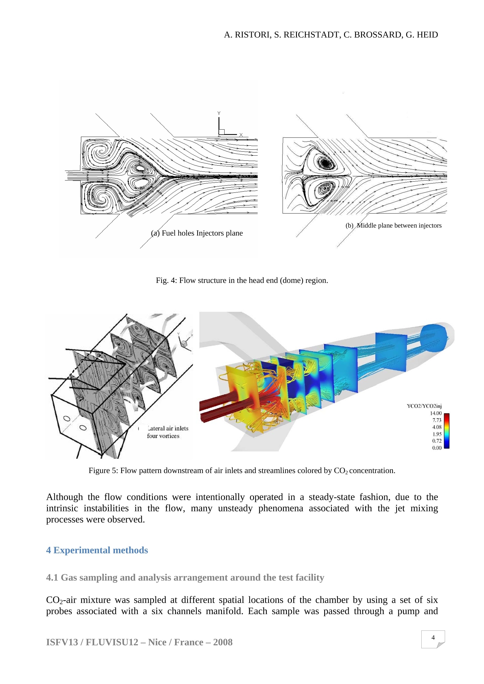
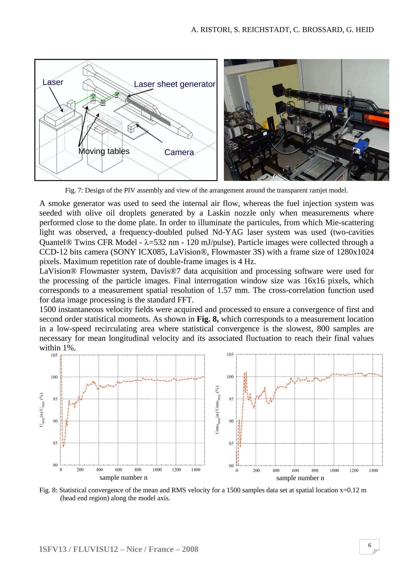
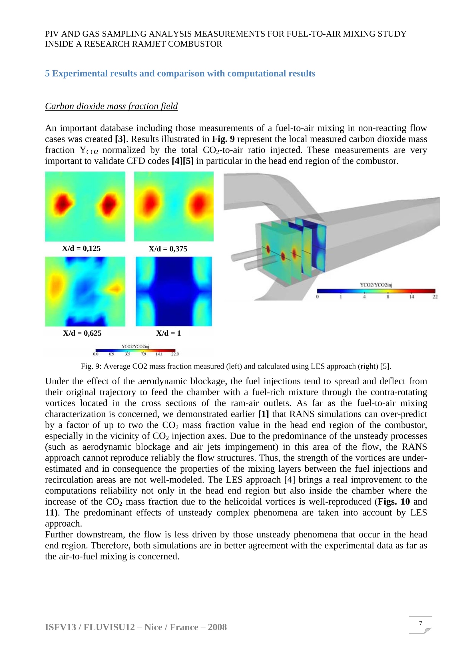
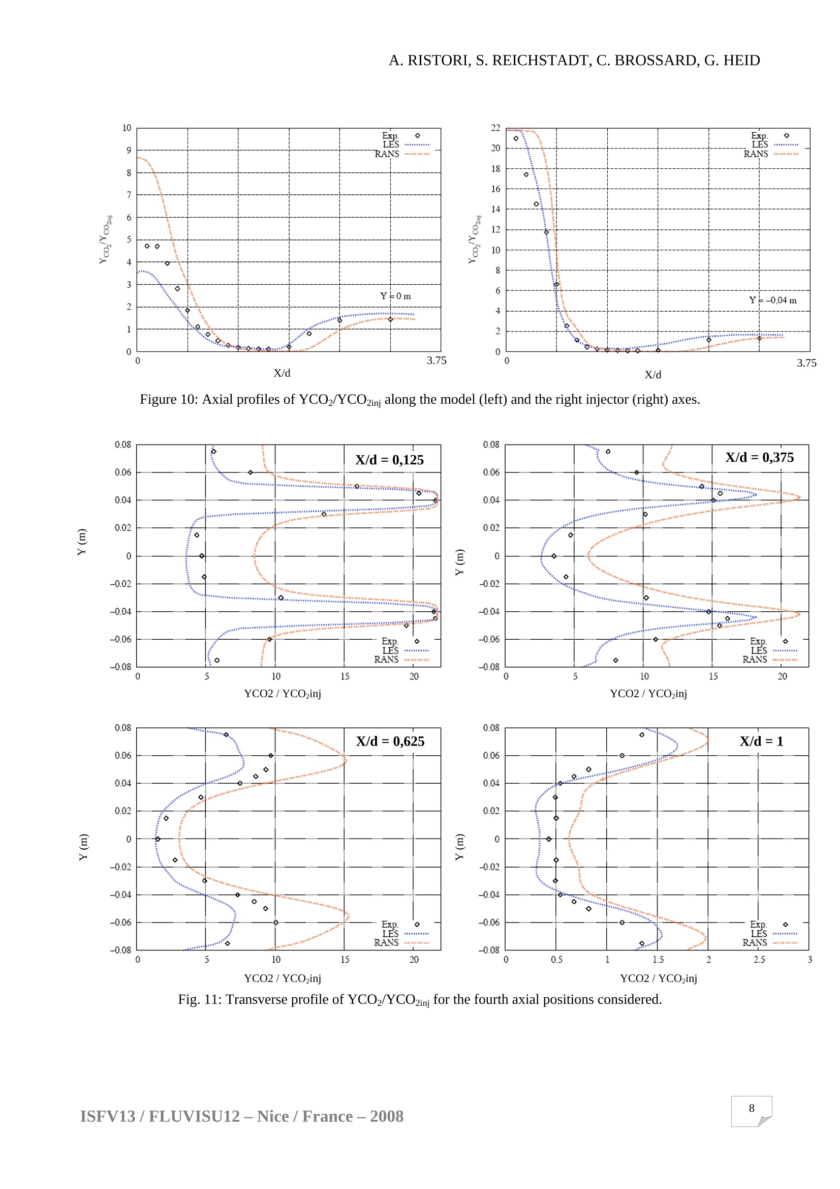
方案详情

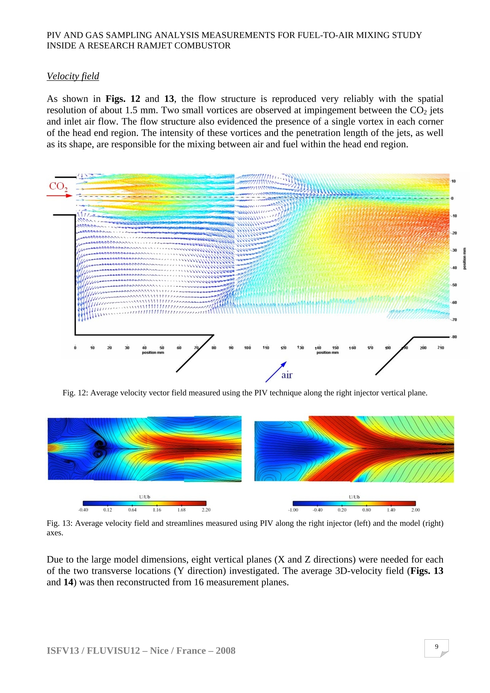
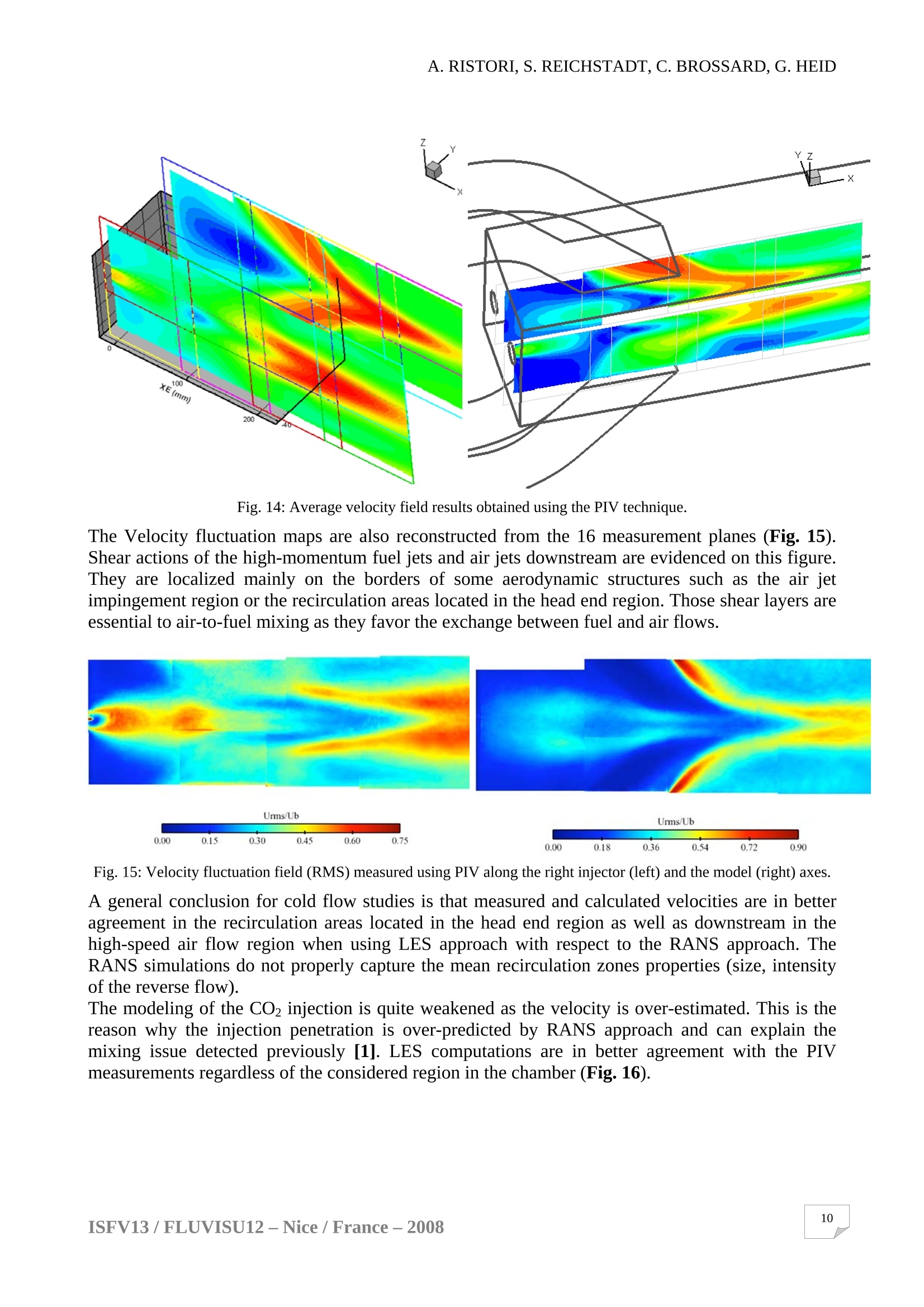
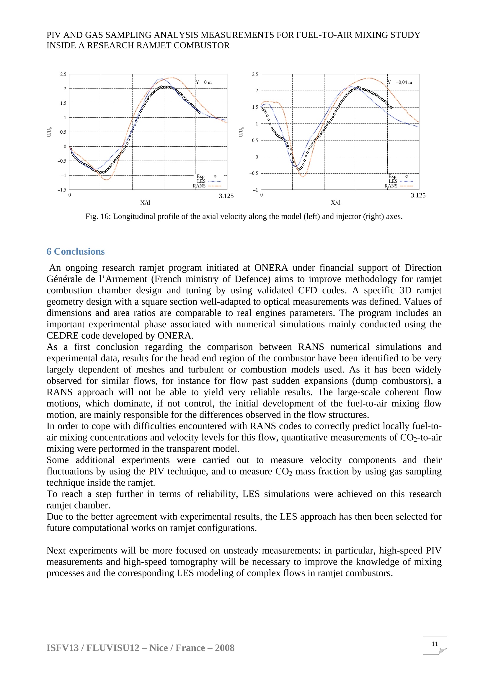
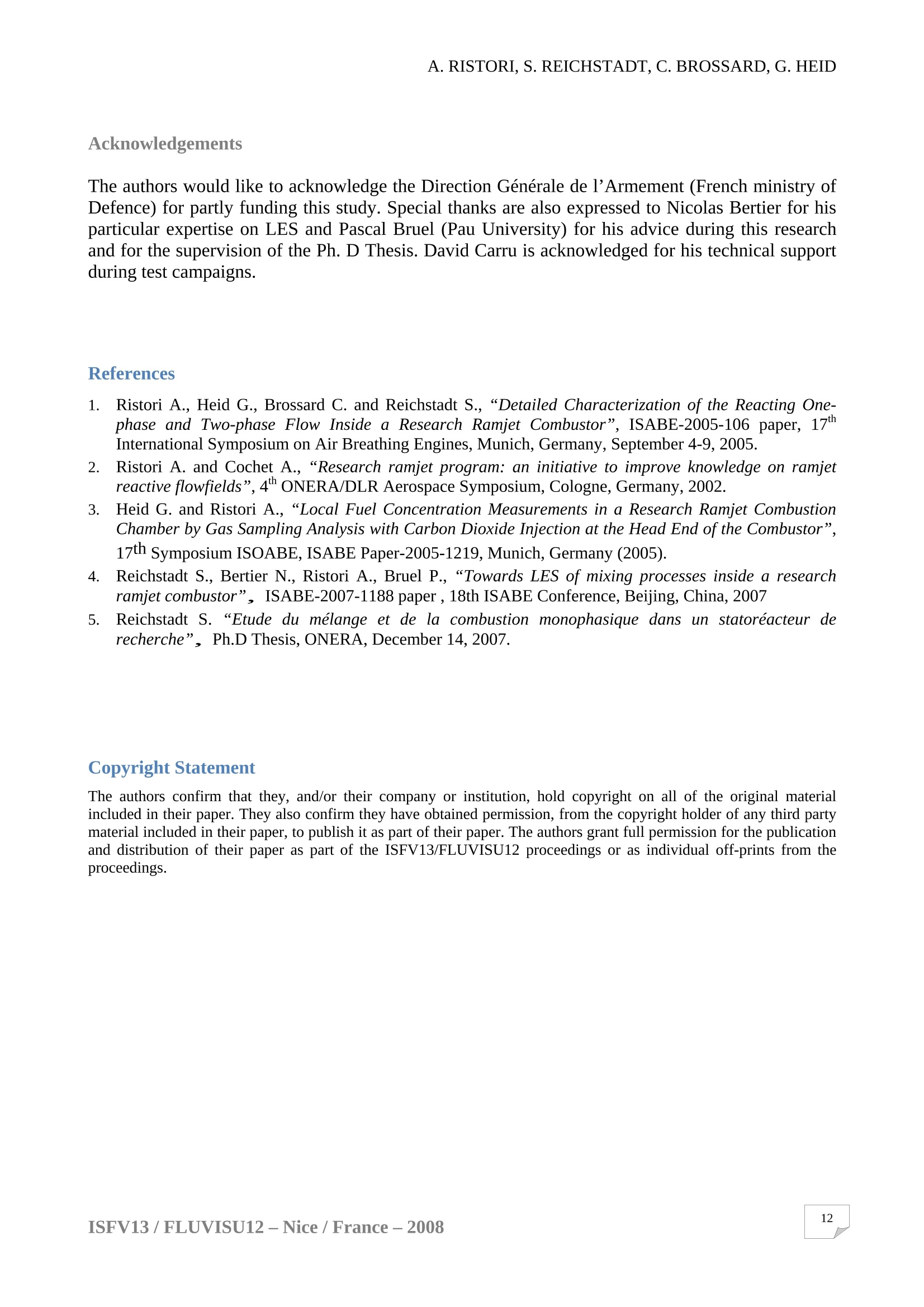
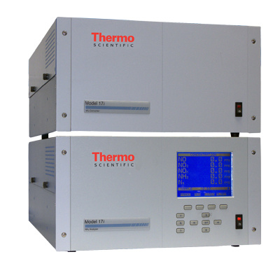
ISFV13-13 International Symposium on Flow VisualizationFLUVISU12 -12" French Congress on Visualization in Fluid MechanicsJuly 1-4,2008, Nice, France A. RISTORI, S.REICHSTADT, C. BROSSARD, G. HEID PIV AND GAS SAMPLING ANALYSIS MEASUREMENTSFOR FUEL-TO-AIR MIXING STUDY INSIDE ARESEARCH RAMJET COMBUSTOR A. Ristori, S. Reichstadt, C. Brossard, G. HeidOffice National d'Etudes et de Recherches Aerospatiales (ONERA) Chemin de la Huniere, F-91761 Palaiseau Cedex, France KEYWORDS: Main subject(s): Ramjet Combustor Fluid: Air, CO2 Visualization method(s): PIV Other keywords: gas sampling analysis ABSTRACT: An ongoing research ramjet program initiated at ONERA under support of DGA(French ministry of Defence) aims to improve methodology for ramjet combustion chamberdesign and tuning by using validated CFD codes. A transparent model rig was used foraerodynamic tests with air flows at atmospheric pressure and room temperature. In the case ofthe simulation of a Solid Ducted Rocket (SDR) combustor, two fuel holes were located at thehead end of the combustor in order to simulate the fuel supply from the auxiliary gas generatorin the case of a real combustor. Among the various mechanisms that are controlling the development of the combustionprocesses inside the combustor, the mixing is certainly one of the most crucial as far as stabilityor efficiency are concerned. Thework presented in this paper isaddressing thecharacterization, in absence of combustion, of the turbulent flow velocity and scalar fieldsassociated to the mixing between fuel (simulated by CO2) and air. Particle image velocimetry(PV) and gas sampling analysis are the two techniques that were used to serve that purpose. Results presented in this paper are very useful to assess the ability of numerical computations,based either on Reynolds-Averaged Navier-Stokes (RANS) or Large-Eddy Simulations (LES)approaches, to reliably predict velocity and fuel concentration fields inside this researchcombustor. 1Introduction ONERA has been involved in ramjet propulsion since its creation in 1946. In the last twenty years,work conducted in close cooperation with industrial partners has greatly developed the knowledgefor this kind of propulsion system. Numerous projects have been conducted up to flight tests:ASMP (“Air To Ground Medium Range Missile", operational since 1986 in French Air Force) andANS (“Predevelopment of Anti-Ship Supersonic Missile”, 1982-1989) are two examples ofmissiles equipped with a liquid-fueled ramjet. Work on ducted rockets should also be mentionedthrough two exploratory developments which are MPSR1 and MPSR2 (“Rustic Ducted RocketMissile”n°1,1981-1985 and n°2, 1990-1995). Until recently, the methodology used to develop ramjet engine and to study ramjet combustorperformances was mainly based on an experimental approach consisting of combustion tests inconnected pipe mode under simulated conditions representative of the studied flight cases. Inaddition to these combustion tests, a method based on cold flow simulations and simplified modelsof flows and combustion was developed in order to attempt to predict the overall combustor operation and to help improving the combustors design. Although this semi-empirical approach isattractive and gives some valuable indications related to engine operation, it is far from sufficient todescribe the local characteristics of the reacting and non-reacting flow fields inside the combustor.Their knowledge is now essential in order to reduce time and cost of development and optimizationof a new ramjet combustion chamber. Nowadays, the improvements of the developmentmethodology heavily rely on Computational Fluid Dynamics (CFD) with validated physical models(more specifically ONERA’s in-house aerothermochemistry code CEDRE) as tools for exploringand testing new and potentially attractive concepts. Therefore it becomes possible to reducesignificantly the number of experimental tests. However, the CFD validation phase requires theavailability of a comprehensive experimental database. This is the reason why, in 1995, with the support of French Official Services (DGA), ONERAinitiated a research ramjet program with the targeted final objective to improve ramjet combustordesign and its methodology. Two three-dimensional research ramjet models were defined [1], withthe aim to build comprehensive experimental databases for non-reacting and reacting flow cases.Among the various mechanisms that are controlling the development of the combustion processesinside the combustor, the mixing is certainly one of the most crucial as far as stability or efficiencyare concerned. The work presented in this paper is about the characterization, in absence ofcombustion, of the turbulent flow velocity and scalar fields associated to the mixing between fueland air. Particle image velocimetry (PIV) and gas sampling analysis are the two techniques thatwere used to serve that purpose. 2 Ramjet Combustor Models The principle of a Solid Ducted Rocket (SDR) is exposed on Fig. 1. The SDR ramjet uses a solidpropellant located in an auxiliary combustor used as a gas generator. The partially burnt productsare ejected trough holes into the head end of the chamber, defined as the domain delimitated at oneend by the dome plate and at the other end by the combustor air inlets. Therefore, they continue toburn with the incoming air inside the combustion chamber. Downstream, the nozzle accelerates theexhaust flow, which results in thrust production. Fig. 1: Principle of a Solid Ducted Ramjet (SDR). Combustion model: With the objective to understand combustion processes inside the combustionchamber, a specific three-dimensional ramjet engine geometry was defined in order to allow foroperating conditions of the combustor (pressure, velocity, temperature) comparable to real motors.The engine configuration considered here consists of a main combustor with two lateral air inlets onopposite sides and an axisymmetric nozzle (Fig. 2) downstream of the combustion chamber. Inorder to facilitate optical access(models equipped with specific glass windows for optical Fig. 2: Research ramjet model (“combustion model") and flame visualization in operation. Transparent model: A specific transparent model at 1.6:1 scale with respect to the combustionmodel was built to perform cold flow experiments (Fig.3) and to characterize the mixing processes.This model is only available for atmospheric tests with water or air flow. For this reason, there is nonozzle at the outlet and the length of the model is reduced compared to the combustion model. Thedimensions of the fuel holes were determined in order to keep constant the ratio of momentumquantity between simulated air and fuel with respect to the combustion model. Further details aboutthe design and test conditions were published earlier [2] [3]. Fig. 3: Schematic viewof the test facility (“transparent model"). 3 Description of the flow pattern The flow structure can be divided into two regions: - the dome region, where two sets of recirculation areas formed mainly under the shear action of thehigh-momentum fuel jets (Fig. 4a) and the flow separation from the inlet edges were observedh)(Fig.4b), - in cross-sections of ram-air outlets, four contra-rotating vortices provide an efficient mechanismfor mixing the ram air with CO2 fuel gases (Fig.5). Fig.4: Flow structure in the head end (dome) region. Figure 5: Flow pattern downstream of air inlets and streamlines colored by CO2 concentration. Although the flow conditions were intentionally operated in a steady-state fashion, due to theintrinsic instabilities in the flow, many unsteady phenomena associated with the jet mixingprocesses were observed. 4 Experimental methods 4.1 Gas sampling and analysis arrangement around the test facility CO2-air mixture was sampled at different spatial locations of the chamber by using a set of sixprobes associated with a six channels manifold. Each sample was passed through a pump and desiccated. Two IR analyzers (Fig.6) were then used simultaneously with, for each of them, threedifferent measurement ranges.The first onewaschosen for measuring low CO2 molarconcentrations (1.5, 5 and 15%) and the second one was devoted to the highest CO2 molarconcentrations measurements (30, 60 and 100%). For each analyzer, the range was automatically setand data were transferred then recorded by a data acquisition system. Before carrying out a series of measurements, a set of CO2 mixture bottles was used to calibrate theanalysers. This measurement technique was presented in more details in a previous paper [3]. Measurementswere mainly achieved in the head end region where the fuel-to-air mixing is essential for thecombustion, which occurs further downstream in the chamber. Fig. 6: View of the gas sampling probes inside the model and of the IR analysis system. 4.2 P.I.V. arrangement around the test facility The use of a PIV system associated with a tracer particles seeding system allowed to measure thevelocity field inside the chamber by letting the laser sheet passing through the head end region(Fig.7). The laser sheets created through a light sheet generator could be moved transversally andhorizontally in order to cover the whole test channel volume. This was achieved thanks to atranslation stage system which moved simultaneously the laser light sheets and camera. Fig. 7:Design of the PIV assembly and view of the arrangement around the transparent ramjet model. A smoke generator was used to seed the internal air flow, whereas the fuel injection system wasseeded with olive oil droplets generated by a Laskin nozzle only when measurements whereperformed close to the dome plate. In order to illuminate the particules, from which Mie-scatteringlight was observed, a frequency-doubled pulsed Nd-YAG laser system was used (two-cavitiesQuantel@ Twins CFR Model -2=532 nm -120 mJ/pulse). Particle images were collected through aCCD-12 bits camera (SONY ICX085, LaVisionQ, Flowmaster 3S) with a frame size of 1280x1024pixels. Maximum repetition rate of double-frame images is 4 Hz. LaVisionQ Flowmaster system, DavisQ7 data acquisition and processing software were used forthe processing of the particle images. Final interrogation window size was 16x16 pixels, whichcorresponds to a measurement spatial resolution of 1.57 mm. The cross-correlation function usedfor data image processing is the standard FFT. 1500 instantaneous velocity fields were acquired and processed to ensure a convergence of first andsecond order statistical moments. As shown in Fig. 8, which corresponds to a measurement locationin a low-speed recirculating area where statistical convergence is the slowest, 800 samples arenecessary for mean longitudinal velocity and its associated fluctuation to reach their final valueswithin 1%. Fig. 8: Statistical convergence of the mean and RMS velocity for a 1500 samples data set at spatial location x=0.12 m(head end region) along the model axis. 5 Experimental results and comparison with computational results Carbon dioxide mass fraction field An important database including those measurements of a fuel-to-air mixing in non-reacting flowcases was created [3]. Results illustrated in Fig. 9 represent the local measured carbon dioxide massfraction Yco2 normalized by the total CO2-to-air ratio injected. These measurements are veryimportant to validate CFD codes [4][5] in particular in the head end region of the combustor. Fig. 9: Average CO2 mass fraction measured (left) and calculated using LES approach (right) [5]. Under the effect of the aerodynamic blockage, the fuel injections tend to spread and deflect fromtheir original trajectory to feed the chamber with a fuel-rich mixture through the contra-rotatingvortices located in the cross sections of the ram-air outlets. As far as the fuel-to-air mixingcharacterization is concerned, we demonstrated earlier [1] that RANS simulations can over-predictby a factor of up to two the CO2 mass fraction value in the head end region of the combustor,especially in the vicinity of CO2 injection axes. Due to the predominance of the unsteady processes(such as aerodynamic blockage and air jets impingement) in this area of the flow, the RANSapproach cannot reproduce reliably the flow structures. Thus, the strength of the vortices are under-estimated and in consequence the properties of the mixing layers between the fuel injections andrecirculation areas are not well-modeled. The LES approach [4] brings a real improvement to thecomputations reliability not only in the head end region but also inside the chamber where theincrease of the CO2 mass fraction due to the helicoidal vortices is well-reproduced (Figs. 10 and11). The predominant effects of unsteady complex phenomena are taken into account by LES approach. Further downstream, the flow is less driven by those unsteady phenomena that occur in the headend region. Therefore, both simulations are in better agreement with the experimental data as far asthe air-to-fuel mixing is concerned. Figure 10: Axial profiles of YCO2/YCO2inj along the model (left) and the right injector (right) axes. Fig. 11: Transverse profile of YCO2/YCO2inj for the fourth axial positions considered. Velocity field As shown in Figs. 12 and 13, the flow structure is reproduced very reliably with the spatialresolution of about 1.5 mm. Two small vortices are observed at impingement between the CO2 jetsand inlet air flow. The flow structure also evidenced the presence of a single vortex in each cornerof the head end region. The intensity of these vortices and the penetration length of the jets, as wellas its shape, are responsible for the mixing between air and fuel within the head end region. Fig. 12: Average velocity vector field measured using the PIV technique along the right injector vertical plane. Fig. 13: Average velocity field and streamlines measured using PIV along the right injector (left) and the model (right)axes. Due to the large model dimensions, eight vertical planes (X and Z directions) were needed for eachof the two transverse locations (Y direction) investigated. The average 3D-velocity field (Figs. 13and 14) was then reconstructed from 16 measurement planes. Fig. 14: Average velocity field results obtained using the PIV technique. The Velocity fluctuation maps are also reconstructed from the 16 measurement planes (Fig. 15).Shear actions ofthe high-momentum fuel jets and air jets downstream are evidenced on this figure.They are localized mainly on the borders of some aerodynamic structures such as the air jetimpingement region or the recirculation areas located in the head end region. Those shear layers areessential to air-to-fuel mixing as they favor the exchange between fuel and air flows. Fig. 15: Velocity fluctuation field (RMS) measured using PIV along the right injector (left) and the model (right) axes. A general conclusion for cold flow studies is that measured and calculated velocities are in betteragreement in the recirculation areas located in the head end region as well as downstream in thehigh-speed air flow region when using LES approach with respect to the RANS approach. TheRANS simulations do not properly capture the mean recirculation zones properties (size,intensityof the reverse flow). The modeling of the CO2 injection is quite weakened as the velocity is over-estimated. This is thereason why the injection penetration is over-predicted by RANS approach and can explain themixing issue detected previously [1]. LES computations are in better agreement with the PIVmeasurements regardless ofthe considered region in the chamber (Fig. 16). 5 Fig. 16: Longitudinal profile of the axial velocity along the model (left) and injector (right) axes. 6 Conclusions An ongoing research ramjet program initiated at ONERA under financial support of DirectionGenerale de I’Armement (French ministry of Defence) aims to improve methodology for ramjetcombustion chamber design and tuning by using validated CFD codes. A specific 3D ramjetgeometry design with a square section well-adapted to optical measurements was defined. Values ofdimensions and area ratios are comparable to real engines parameters. The program includes animportant experimental phase associated with numerical simulations mainly conducted using theCEDRE code developed by ONERA. Asa first conclusion regarding the comparison between IRANS numerical simulationss andexperimental data, results for the head end region of the combustor have been identified to be verylargely dependent of meshes and turbulent or combustion models used. As it has been widelyobserved for similar flows, for instance for flow past sudden expansions (dump combustors), aRANS approach will not be able to yield very reliable results. The large-scale coherent flowmotions, which dominate, if not control, the initial development of the fuel-to-air mixing flowmotion, are mainly responsible for the differences observed in the flow structures. In order to cope with difficulties encountered with RANS codes to correctly predict locally fuel-to-air mixing concentrations and velocity levels for this flow, quantitative measurements of CO2-to-airmixing were performed in the transparent model. Some additional experimentswere carried out to measure velocity components and theirfluctuations by using the PIV technique, and to measure CO2 mass fraction by using gas samplingtechnique inside the ramjet. To reach a step further in terms of reliability, LES simulations were achieved on this researchramjet chamber. Due to the better agreement with experimental results, the LES approach has then been selected forfuture computational works on ramjet configurations. Next experiments will be more focused on unsteady measurements: in particular, high-speed PIVmeasurements and high-speed tomography will be necessary to improve the knowledge of mixingprocesses and the corresponding LES modeling of complex flows in ramjet combustors. Acknowledgements The authors would like to acknowledge the Direction Generale de I'Armement (French ministry ofDefence) for partly funding this study. Special thanks are also expressed to Nicolas Bertier for hisparticular expertise on LES and Pascal Bruel (Pau University) for his advice during this researchand for the supervision of the Ph. D Thesis. David Carru is acknowledged for his technical supportduring test campaigns. References 1.Ristori A., Heid G., Brossard C. and Reichstadt S., “Detailed Characterization of the Reacting One-phase and Two-phase Flow Inside a Research Ramjet Combustor”, ISABE-2005-106 paper, 17"International Symposium on Air Breathing Engines,Munich, Germany, September 4-9, 2005. 2. Ristori A. and Cochet A.“Research ramjet program: an initiative to improve knowledge on ramjetreactive flowfields”, 4" ONERA/DLR Aerospace Symposium, Cologne, Germany, 2002. 3. Heid G. and Ristori A., “Local Fuel Concentration Measurements in a Research Ramjet CombustionChamber by Gas Sampling Analysis with Carbon Dioxide Injection at the Head End of the Combustor”,17th Symposium ISOABE, ISABE Paper-2005-1219, Munich, Germany (2005). 4. Reichstadt S., Bertier N., Ristori A., Bruel P.,““Towards LES ofmixing processes inside a researchramjet combustor”, ISABE-2007-1188 paper , 18th ISABE Conference, Beijing, China, 2007 5. Reichstadt S.“Etude du melange et de la combustion monophasique dans un statoreacteur derecherche" Ph.D Thesis, ONERA, December 14, 2007. Copyright Statement The authors confirm that they, and/or their company or institution, hold copyright on all of the original materialincluded in their paper. They also confirm they have obtained permission, from the copyright holder of any third partymaterial included in their paper, to publish it as part of their paper. The authors grant full permission for the publicationand distribution of their paper as part of the ISFV13/FLUVISU12 proceedings or as individual off-prints from theproceedings. ISFVFLUVISU Nice/ France -
确定


还剩10页未读,是否继续阅读?

产品配置单


北京欧兰科技发展有限公司为您提供《冲压发动机,燃烧器,燃料和空气混合过程中速度场,燃料浓度场检测方案(粒子图像测速)》,该方案主要用于其他中速度场,燃料浓度场检测,参考标准--,《冲压发动机,燃烧器,燃料和空气混合过程中速度场,燃料浓度场检测方案(粒子图像测速)》用到的仪器有德国LaVision PIV/PLIF粒子成像测速场仪、PLIF平面激光诱导荧光火焰燃烧检测系统、激光诱导白炽光烟雾粒子成像分析仪(LII)
推荐专场


相关方案
更多
该厂商其他方案
更多