


采用LaVision公司的2D-PIV系统和Artium公司相位多普勒粒子干涉仪,对一种新型燃气轮机燃烧室双相喷射器的喷雾特性和速度分布特性进行了实验测量和研究。
方案详情

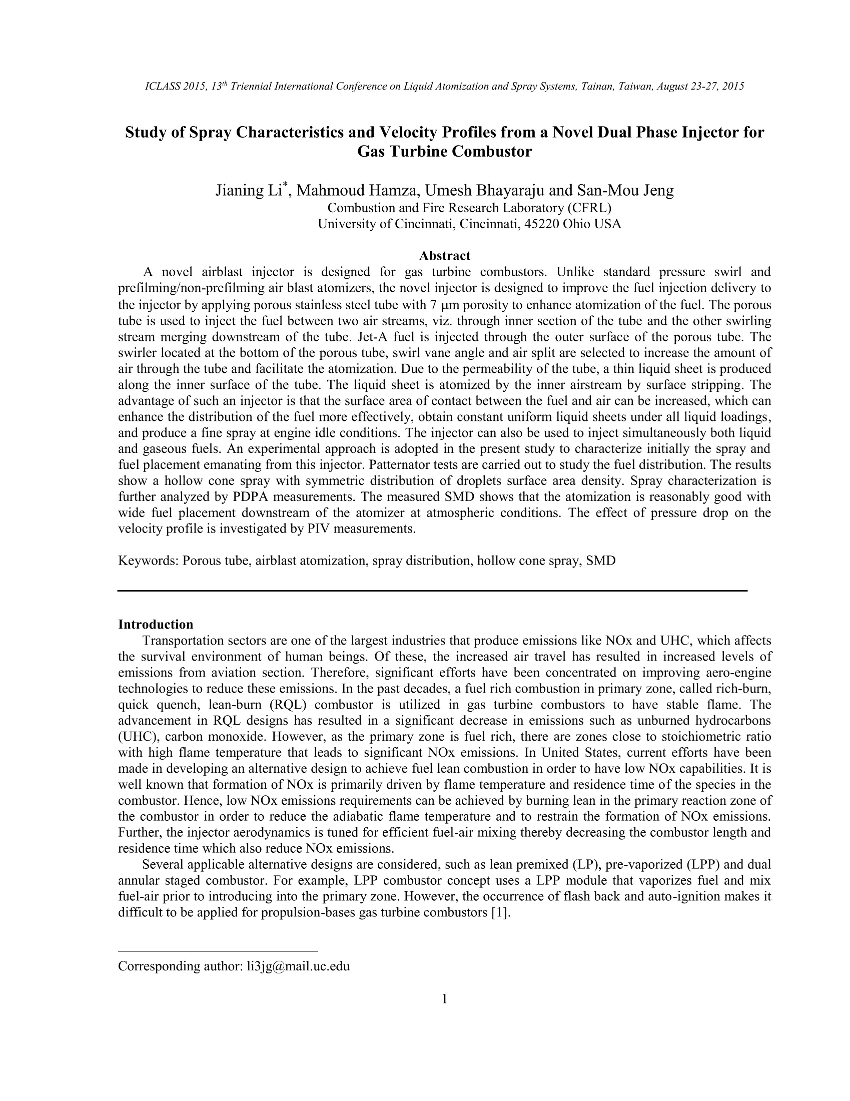
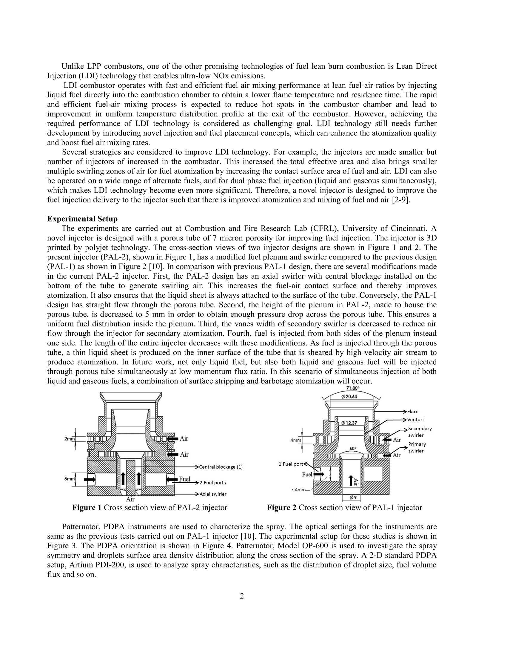
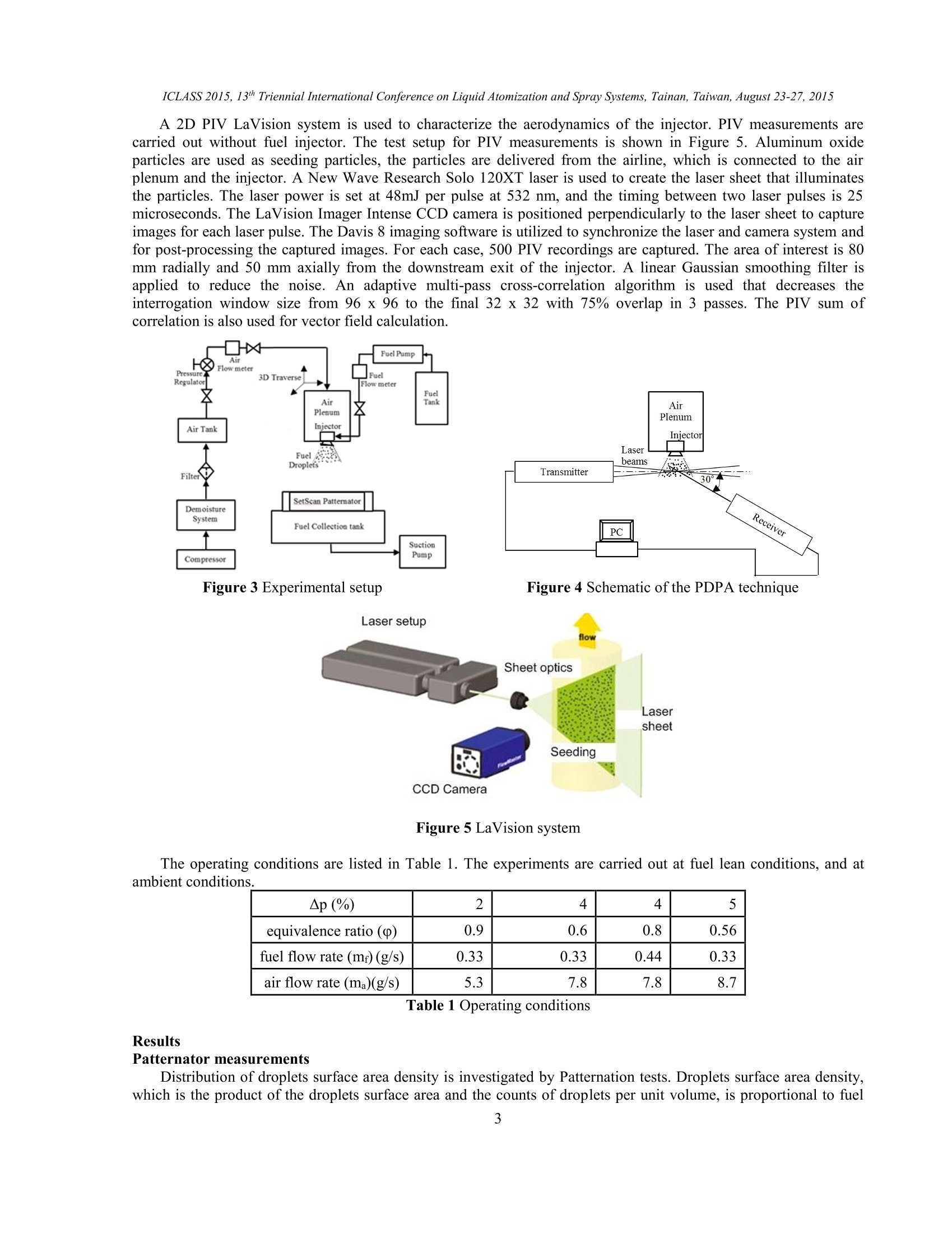
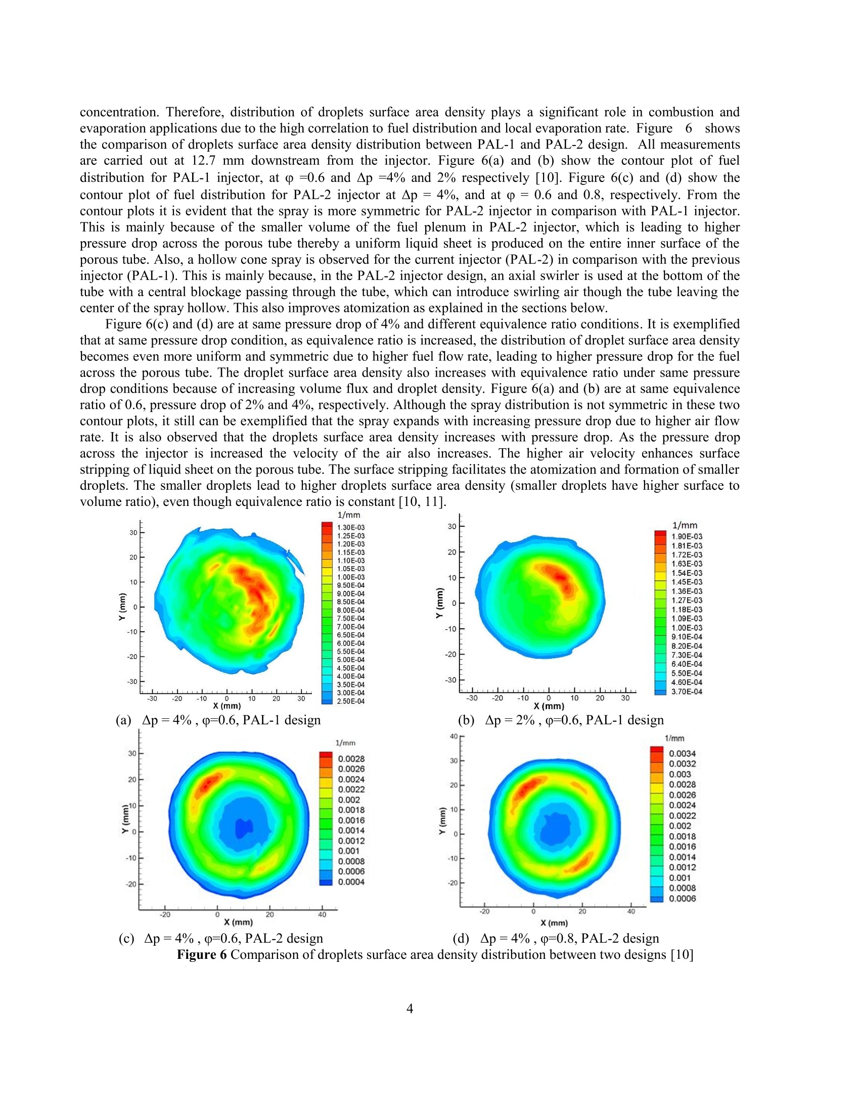
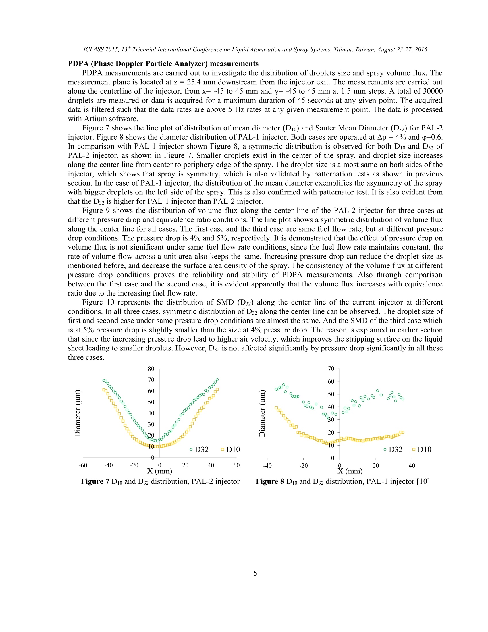
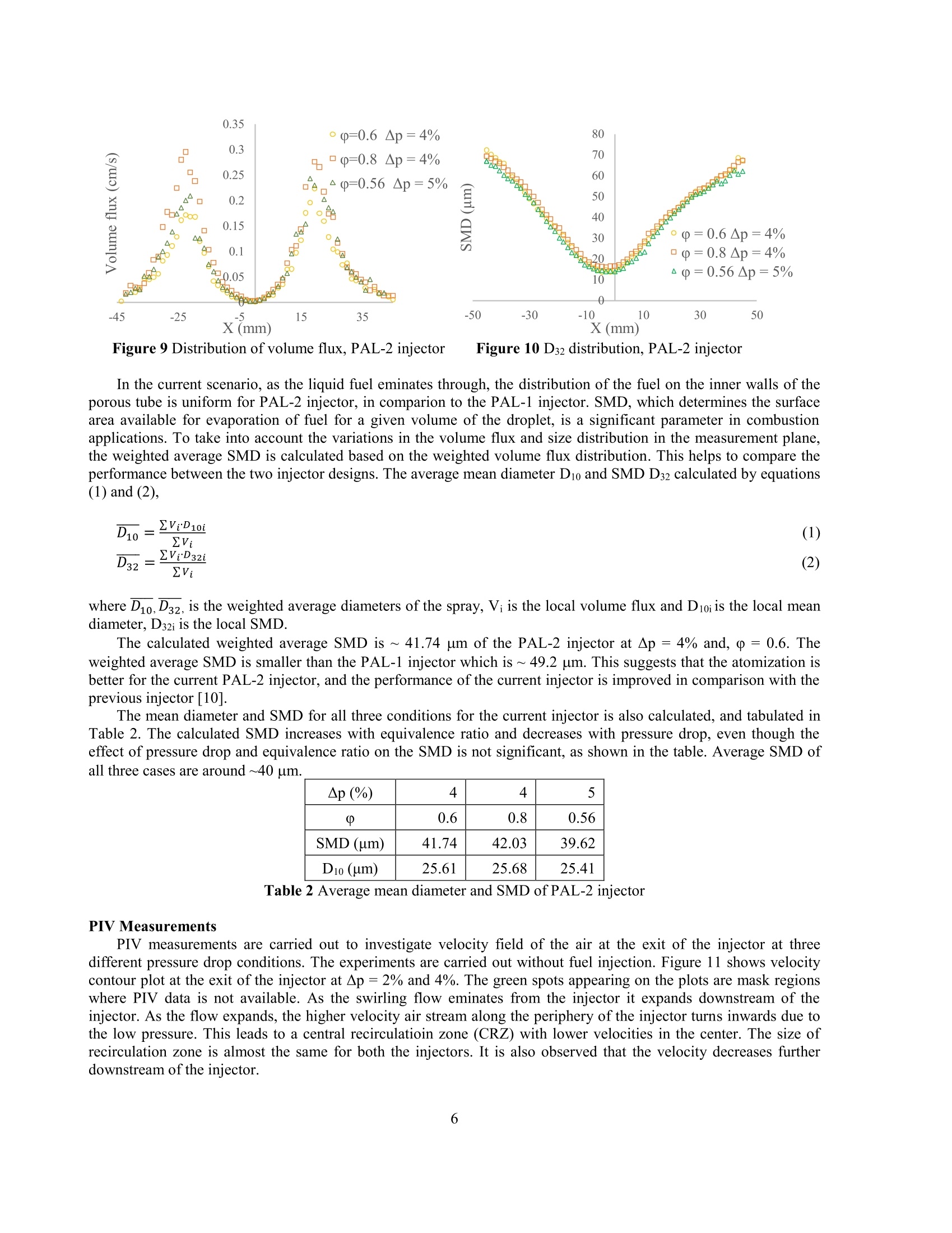
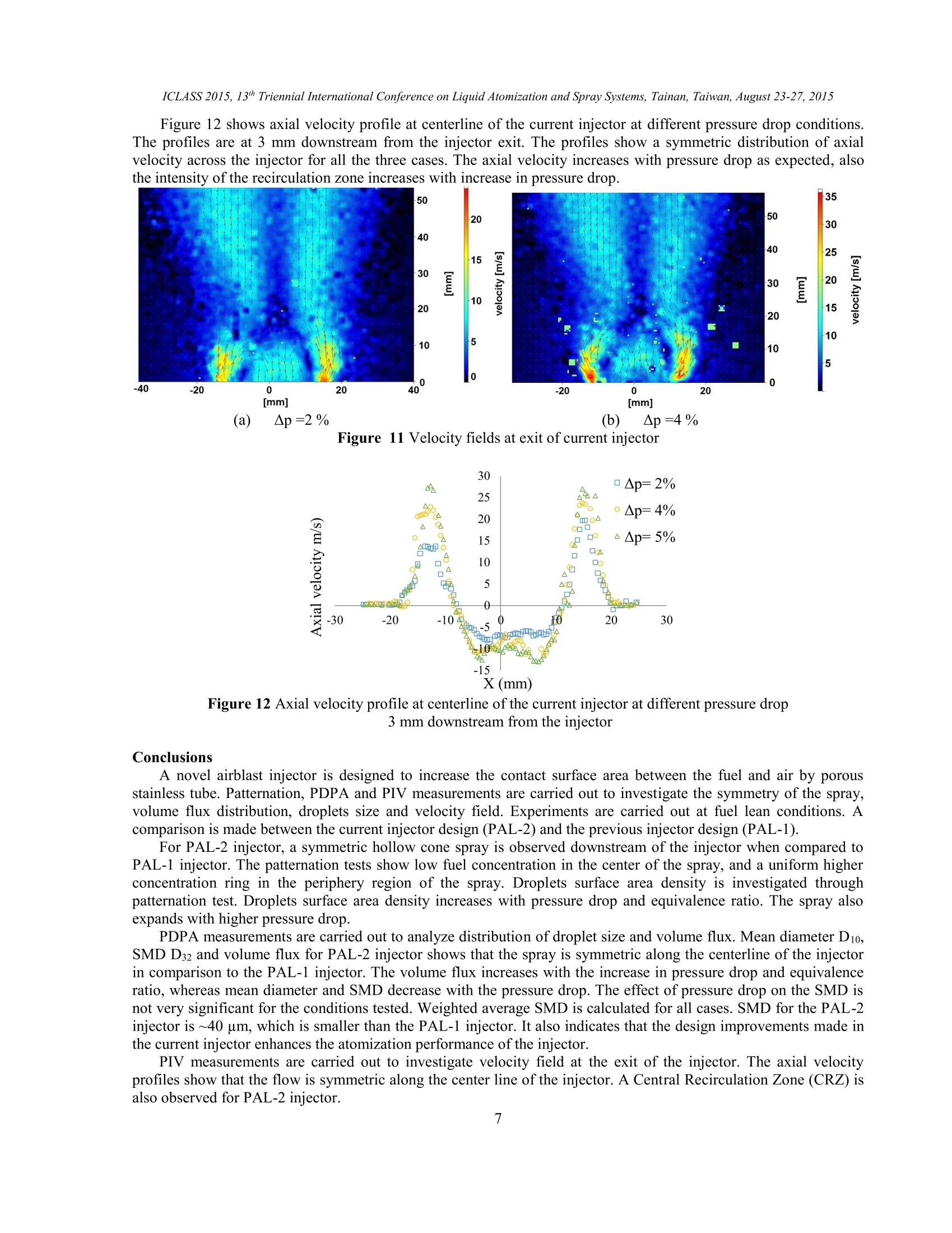
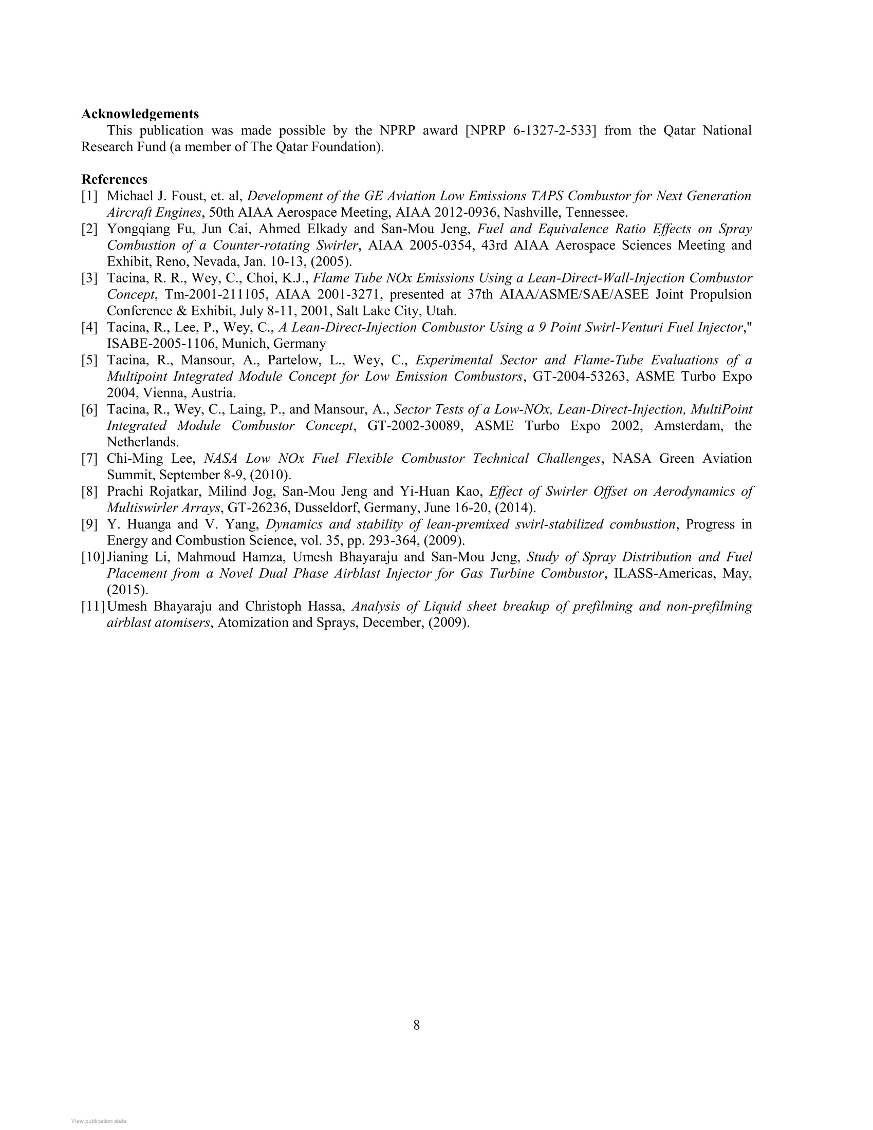
ResearchGateSee discussions, stats, and author profiles for this publication at: https://www.researchgate.net/publication/304626766 ICLASS 2015, 13th Triennial International Conference on Liquid Atomization and Spray Systems, Tainan, Taiwan, August 23-27, 2015 Study of Spray Characteristics and Velocity Profiles from a Novel Dual PhaseInjector for Gas Turbine Combustor Conference Paper·August 2015 CITATIONS0 READS 80 4 authors,including: Jianing Li University of Cincinnati Mahmoud HamzaUniversity of Cincinnati 6 PUBLICATIONS 2 CITATIONS 7 PUBLICATIONS 4 CITATIONS SEE PROFILE SEE PROFILE Umesh Bhayaraju University of Cincinnati 22PUBLICATIONS 66 CITATIONS SEE PROFILE Some of the authors of this publication are also working on these related projects: Project DIr koeln View project Study of Spray Characteristics and Velocity Profiles from a Novel Dual Phase Injector forGas Turbine Combustor Jianing Li, Mahmoud Hamza, Umesh Bhayaraju and San-Mou Jeng Combustion and Fire Research Laboratory (CFRL) University of Cincinnati, Cincinnati, 45220 Ohio USA Abstract A novel airblast injector is designed for gas turbine combustors. Unlike standard pressure swirl andprefilming/non-prefilming air blast atomizers, the novel injector is designed to improve the fuel injection delivery tothe injector by applying porous stainless steel tube with 7 um porosity to enhance atomization of the fuel. The poroustube is used to inject the fuel between two air streams, viz. through inner section of the tube and the other swirlingstream merging downstream of the tube. Jet-A fuel is injected through the outer surface of the porous tube. Theswirler located at the bottom of the porous tube, swirl vane angle and air split are selected to increase the amount ofair through the tube and facilitate the atomization. Due to the permeability of the tube, a thin liquid sheet is producedalong the inner surface of the tube. The liquid sheet is atomized by the inner airstream by surface stripping. Theadvantage of such an injector is that the surface area of contact between the fuel and air can be increased, which canenhance the distribution of the fuel more effectively, obtain constant uniform liquid sheets under all liquid loadings,and produce a fine spray at engine idle conditions. The injector can also be used to inject simultaneously both liquidand gaseous fuels. An experimental approach is adopted in the present study to characterize initially the spray andfuel placement emanating from this injector. Patternator tests are carried out to study the fuel distribution. The resultsshow a hollow cone spray with symmetric distribution of droplets surface area density. Spray characterization isfurther analyzed by PDPA measurements. The measured SMD shows that the atomization is reasonably good withwide fuel placement downstream of the atomizer at atmospheric conditions. The effect of pressure drop on thevelocity profile is investigated by PIV measurements. Keywords: Porous tube, airblast atomization, spray distribution, hollow cone spray, SMD Introduction Transportation sectors are one of the largest industries that produce emissions like NOx and UHC, which affectsthe survival environment of human beings. Of these, the increased air travel has resulted in increased levels ofemissions from aviation section. Therefore, significant efforts have been concentrated on improving aero-enginetechnologies to reduce these emissions. In the past decades, a fuel rich combustion in primary zone, called rich-burn,quick quench, lean-burn (RQL) combustor is utilized in gas turbine combustors to have stable flame. Theadvancement in RQL designs has resulted in a significant decrease in emissions such as unburned hydrocarbons(UHC), carbon monoxide. However, as the primary zone is fuel rich, there are zones close to stoichiometric raticwith high flame temperature that leads to significant NOx emissions. In United States, current efforts have beenmade in developing an alternative design to achieve fuel lean combustion in order to have low NOx capabilities. It iswell known that formation of NOx is primarily driven by flame temperature and residence time of the species in thecombustor. Hence, low NOx emissions requirements can be achieved by burning lean in the primary reaction zone ofthe combustor in order to reduce the adiabatic flame temperature and to restrain the formation of NOx emissions.Further, the injector aerodynamics is tuned for efficient fuel-air mixing thereby decreasing the combustor length andresidence time which also reduce NOx emissions. Several applicable alternative designs are considered, such as lean premixed (LP), pre-vaporized (LPP) and dualannular staged combustor. For example, LPP combustor concept uses a LPP module that vaporizes fuel and mixfuel-air prior to introducing into the primary zone. However, the occurrence of flash back and auto-ignition makes itdifficult to be applied for propulsion-bases gas turbine combustors [1]. Unlike LPP combustors, one of the other promising technologies of fuel lean burn combustion is Lean DirectInjection (LDI) technology that enables ultra-low NOx emissions. LDI combustor operates with fast and efficient fuel air mixing performance at lean fuel-air ratios by injectingliquid fuel directly into the combustion chamber to obtain a lower flame temperature and residence time. The rapidand efficient fuel-air mixing process is expected to reduce hot spots in the combustor chamber and lead toimprovement in uniform temperature distribution profile at the exit of the combustor. However, achieving therequired performance of LDI technology is considered as challenging goal. LDI technology still needs furtherdevelopment by introducing novel injection and fuel placement concepts, which can enhance the atomization qualityand boost fuel air mixing rates. Several strategies are considered to improve LDI technology. For example, the injectors are made smaller butnumber ofinjectors of increased in the combustor. This increased the total effective area and also brings smallermultiple swirling zones of air for fuel atomization by increasing the contact surface area of fuel and air. LDI can alsobe operated on a wide range of alternate fuels, and for dual phase fuel injection (liquid and gaseous simultaneously),which makes LDI technology become even more significant. Therefore, a novel injector is designed to improve thefuel injection delivery to the injector such that there is improved atomization and mixing of fuel and air [2-9]. Experimental Setup The experimentInes are carried out at Combustion and Fire Research Lab (CFRL), University of Cincinnati. Anovel injector is designed with a porous tube of 7 micron porosity for improving fuel injection. The injector is 3Dprinted by polyjet technology. The cross-section views of two injector designs are shown in Figure 1 and 2. Thepresent injector (PAL-2), shown in Figure 1, has a modified fuel plenum and swirler compared to the previous design(PAL-1) as shown in Figure 2 [10]. In comparison with previous PAL-1 design, there are several modifications madein the current PAL-2 injector. First, the PAL-2 design has an axial swirler with central blockage installed on thebottom of the tube to generate swirling air. This increases the fuel-air contact surface and thereby improvesatomization. It also ensures that the liquid sheet is always attached to the surface of the tube. Conversely, the PAL-1design has straight flow through the porous tube. Second, the height of the plenum in PAL-2, made to house theporous tube, is decreased to 5 mm in order to obtain enough pressure drop across the porous tube. This ensures auniform fuel distribution inside the plenum. Third, the vanes width of secondary swirler is decreased to reduce airflow through the injector for secondary atomization. Fourth, fuel is injected from both sides of the plenum insteadone side. The length of the entire injector decreases with these modifications. As fuel is injected through the poroustube, a thin liquid sheet is produced on the inner surface of the tube that is sheared by high velocity air stream toproduce atomization. In future work, not only liquid fuel, but also both liquid and gaseous fuel will be injectedthrough porous tube simultaneously at low momentum flux ratio. In this scenario of simultaneous injection of bothliquid and gaseous fuels, a combination of surface stripping and barbotage atomization will occur. 71.80° Figure 1 Cross section view of PAL-2 injector Figure 2 Cross section view of PAL-1 injector Patternator, PDPA instruments are used to characterize the spray. The optical settings for the instruments aresame as the previous tests carried out on PAL-1 injector [10]. The experimental setup for these studies is shown inFigure 3. The PDPA orientation is shown in Figure 4. Patternator, Model OP-600 is used to investigate the spraysymmetry and droplets surface area density distribution along the cross section of the spray. A 2-D standard PDPAsetup, Artium PDI-200, is used to analyze spray characteristics, such as the distribution of droplet size, fuel volumeflux and so on. A 2D PIV LaVision system is used to characterize the aerodynamics of the injector. PIV measurements arecarried out without fuel injector. The test setup for PIV measurements is shown in Figure 5. Aluminum oxideparticles are used as seeding particles, the particles are delivered from the airline, which is connected to the airplenum and the injector. A New Wave Research Solo 120XT laser is used to create the laser sheet that illuminatesthe particles. The laser power is set at 48mJ per pulse at 532 nm, and the timing between two laser pulses is 25microseconds. The LaVision Imager Intense CCD camera is positioned perpendicularly to the laser sheet to captureimages for each laser pulse. The Davis 8 imaging software is utilized to synchronize the laser and camera system andfor post-processing the captured images. For each case, 500 PIV recordings are captured. The area of interest is 80mm radially and 50 mm axially from the downstream exit of the injector. A linear Gaussian smoothing filter isapplied to reduce the noise. An adaptive multi-pass cross-correlation algorithm is used that decreases theinterrogation window size from 96 x 96 to the final 32 x 32 with 75% overlap in 3 passes. The PIV sum ofcorrelation is also used for vector field calculation. Figure 3 Experimental setup Figure 4 Schematic of the PDPA technique Figure 5 LaVision system The operating conditions are listed in Table 1. The experiments are carried out at fuel lean conditions, and atambient conditions. Ap(%) 2 4 4 5 equivalence ratio (() 0.9 0.6 0.8 0.56 fuel flow rate (mr) (g/s) 0.33 0.33 0.44 0.33 air flow rate (ma)(g/s) 5.3 7.8 7.8 8.7 Table 1 Operating conditions Results Patternator measurements Distribution of droplets surface area density is investigated by Patternation tests. Droplets surface area density,which is the product of the droplets surface area and the counts of droplets per unit volume, is proportional to fuel concentration. Therefore, distribution of droplets surface area density plays a significant role in combustion andevaporation applications due to the high correlation to fuel distribution and local evaporation rate. Figure 6 showsthe comparison of droplets surface area density distribution between PAL-1 and PAL-2 design. All measurementsare carried out at 12.7 mm downstream from the injector. Figure 6(a) and (b) show the contour plot of fueldistribution for PAL-1 injector, at p =0.6 and Ap =4% and 2% respectively [10]. Figure 6(c) and (d) show thecontour plot of fuel distribution for PAL-2 injector at Ap=4%, and at p= 0.6 and 0.8, respectively. From thecontour plots it is evident that the spray is more symmetric for PAL-2 injector in comparison with PAL-1 injector.This is mainly because of the smaller volume of the fuel plenum in PAL-2 injector, which is leading to higherpressure drop across the porous tube thereby a uniform liquid sheet is produced on the entire inner surface of theporous tube. Also, a hollow cone spray is observed for the current injector (PAL-2) in comparison with the previousinjector (PAL-1). This is mainly because, in the PAL-2 injector design, an axial swirler is used at the bottom of thetube with a central blockage passing through the tube, which can introduce swirling air though the tube leaving thecenter of the spray hollow. This also improves atomization as explained in the sections below. Figure 6(c) and (d) are at same pressure drop of 4%and different equivalence ratio conditions. It is exemplifiedthat at same pressure drop condition, as equivalence ratio is increased, the distribution of droplet surface area densitybecomes even more uniform and symmetric due to higher fuel flow rate, leading to higher pressure drop for the fuelacross the porous tube. The droplet surface area density also increases with equivalence ratio under same pressuredrop conditions because of increasing volume flux and droplet density. Figure 6(a) and (b) are at same equivalenceratio of 0.6, pressure drop of2% and 4%, respectively. Although the spray distribution is not symmetric in these twocontour plots, it still can be exemplified that the spray expands with increasing pressure drop due to higher air flowrate. It is also observed that the droplets surface area density increases with pressure drop. As the pressure dropacross the injector is increased the velocity of the air also increases. The higher air velocity enhances surfastrippingce of liquid sheet on the porous tube. The surface stripping facilitates the atomization and formation of smallerdroplets. The smaller droplets lead to higher droplets surface area density (smaller droplets have higher surface tovolume ratio), even though equivalence ratio is constant [10, 11]. EE> X(mm) (a)Ap=4%,p=0.6,PAL-1 design Ap=2%,p=0.6, PAL-1 design (c) Ap=4%,p=0.6, PAL-2 design (d) Ap=4%,p=0.8, PAL-2 design Figure 6 Comparison of droplets surface area density distribution between two designs [10] PDPA (Phase Doppler Particle Analyzer) measurements PDPA measurements are carried out to investigate the distribution of droplets size and spray volume flux. Themeasurement plane is located at z =25.4 mm downstream from the injector exit. The measurements are carried outalong the centerline of the injector, from x=-45 to 45 mm and y= -45 to 45 mm at 1.5 mm steps. A total of 30000droplets are measured or data is acquired for a maximum duration of 45 seconds at any given point. The acquireddata is filtered such that the data rates are above 5 Hz rates at any given measurement point. The data is processedwith Artium software. Figure 7 shows the line plot of distribution of mean diameter (Di0) and Sauter Mean Diameter (D32) for PAL-2injector. Figure 8 shows the diameter distribution of PAL-1 injector. Both cases are operated at Ap=4% and p=0.6.In comparison with PAL-1 injector shown Figure 8, a symmetric distribution is observed for both Dio and D32 ofPAL-2 injector, as shown in Figure 7. Smaller droplets exist in the center of the spray, and droplet size increasesalong the center line from center to periphery edge of the spray. The droplet size is almost same on both sides of theinjector, which shows that spray is symmetry, which is also validated by patternation tests as shown in previoussection. In the case of PAL-1 injector, the distribution of the mean diameter exemplifies the asymmetry of the spraywith bigger droplets on the left side of the spray. This is also confirmed with patternator test. It is also evident fromthat the D32 is higher for PAL-1 injector than PAL-2 injector. Figure 9 shows the distribution of volume flux along the center line of the PAL-2 injector for three cases atdifferent pressure drop and equivalence ratio conditions. The line plot shows a symmetric distribution of volume fluxalong the center line for all cases. The first case and the third case are same fuel flow rate, but at different pressuredrop conditions. The pressure drop is 4% and 5%, respectively. It is demonstrated that the effect of pressure drop onvolume flux is not significant under same fuel flow rate conditions, since the fuel flow rate maintains constant, therate of volume flow across a unit area also keeps the same. Increasing pressure drop can reduce the droplet size asmentioned before, and decrease the surface area density of the spray. The consistency of the volume flux at differentpressure drop conditions proves the reliability and stability of PDPA measurements. Also through comparisonbetween the first case and the second case, it is evident apparently that the volume flux increases with equivalenceratio due to the increasing fuel flow rate. Figure 10 represents the distribution of SMD (D32) along the center line of the current injector at differentconditions. In all three cases, symmetric distribution of D32 along the center line can be observed. The droplet size offirst and second case under same pressure drop conditions are almost the same. And the SMD of the third case whichis at 5% pressure drop is slightly smaller than the size at 4% pressure drop. The reason is explained in earlier sectionthat since the increasing pressure drop lead to higher air velocity, which improves the stripping surface on the liquidsheet leading to smaller droplets. However, D32 is not affected significantly by pressure drop significantly in all thesethree cases. Figure 7 Dio and D32 distribution, PAL-2 injector Figure 8 D1o and D32 distribution, PAL-1 injector [10] Figure 9 Distribution of volume flux, PAL-2 injector Figure 10 D32 distribution, PAL-2 injector In the current scenario, as the liquid fuel eminates through, the distribution of the fuel on the inner walls of theporous tube is uniform for PAL-2 injector, in comparion to the PAL-1 injector. SMD, which determines the surfacearea available for evaporation of fuel for a given volume of the droplet, is a significant parameter in combustionapplications. To take into account the variations in the volume flux and size distribution in the measurement plane,the weighted average SMD is calculated based on the weighted volume flux distribution. This helps to compare theperformance between the two injector designs. The average mean diameter D1o and SMD D32 calculated by equations(1) and (2), (2) ZV; where D10,D32, is the weighted average diameters of the spray, Vi is the local volume flux and Dioi is the local meandiameter, D32i is the local SMD. The calculated weighted average SMD is ~ 41.74 um of the PAL-2 injector at Ap= 4% and, p=0.6. Theweighted average SMD is smaller than the PAL-1 injector which is ~49.2 um. This suggests that the atomization isbetter for the current PAL-2 injector, and the performance ofthe current injector is improved in comparison with theprevious injector [10]. The mean diameter and SMD for all three conditions for the current injector is also calculated, and tabulated inTable 2. The calculated SMD increases with equivalence ratio and decreases with pressure drop, even though theeffect of pressure drop and equivalence ratio on the SMD is not significant, as shown in the table. Average SMD ofall three cases are around ~40 um. △p (%) 4 4 5 0.6 0.8 0.56 SMD (um) 41.74 42.03 39.62 Dio (um) 25.61 25.68 25.41 Table 2 Average mean diameter and SMD of PAL-2 injector PIV Measurements PIV measurements are carried out to investigate velocity field of the air at the exit of the injector at threedifferent pressure drop conditions. The experiments are carried out without fuel injection. Figure 11 shows velocitycontour plot at the exit of the injector at Ap=2% and 4%. The green spots appearing on the plots are mask regionswhere PIV data is not available. As the swirling flow eminates from the injector it expands downstream of theinjector. As the flow expands, the higher velocity air stream along the periphery of the injector turns inwards due tothe low pressure. This leads to a central recirculatioin zone (CRZ) with lower velocities in the center. The size ofrecirculation zone is almost the same for both the injectors. It is also observed that the velocity decreases furtherdownstream of the injector. Figure 12 shows axial velocity profile at centerline of the current injector at different pressure drop conditions.The profiles are at 3 mm downstream from the injector exit. The profiles show a symmetric distribution of axialvelocity across the injector for all the three cases. The axial velocity increases with pressure drop as expected, alsothe intensity of the recirculation zone increases with increase in pressure drop. Figure 11 Velocity fields at exit of current injector Figure 12 Axial velocity profile at centerline of the current injector at different pressure drop3 mm downstream from the injector Conclusions A novel airblast injector is designed to increase the contact surface area between the fuel and air by porousstainless tube.Patternation, PDPA and PIV measurements are carried out to investigate the symmetry of the spray,volume flux distribution, droplets size and velocity field. Experiments are carried out at fuel lean conditions. Acomparison is made between the current injector design (PAL-2) and the previous injector design (PAL-1). For PAL-2 injector, a symmetric hollow cone spray is observed downstream of the injector when compared toPAL-1 injector. The patternation tests show low fuel concentration in the center of the spray, and a uniform higherconcentration ring in the periphery region of the spray. Droplets surface area density is investigated throughpatternation test. Droplets surface area density increases with pressure drop and equivalence ratio. The spray alsoexpands with higher pressure drop. PDPA measurements are carried out to analyze distribution of droplet size and volume flux. Mean diameter D10,SMD D32 and volume flux for PAL-2 injector shows that the spray is symmetric along the centerline of the injectorin comparison to the PAL-1 injector. The volume flux increases with the increase in pressure drop and equivalenceratio, whereas mean diameter and SMD decrease with the pressure drop. The effect of pressure drop on the SMD isnot very significant for the conditions tested. Weighted average SMD is calculated for all cases. SMD for the PAL-2injector is ~40 um, which is smaller than the PAL-1 injector. It also indicates that the design improvements made inthe current injector enhances the atomization performance of the injector. PIV measurements are carried out to investigate velocity field at the exit of the injector. The axial velocityprofiles show that the flow is symmetric along the center line of the injector. A Central Recirculation Zone (CRZ) isalso observed for PAL-2 injector. Acknowledgements This publication was made possible by the NPRP award [NPRP 6-1327-2-533] from the Qatar NationalResearch Fund (a member of The Qatar Foundation). ( References ) [1] Michael J. Foust, et. al, Development of the GE Aviation Low Emissions TAPS Combustor for Next GenerationAircraft Engines, 50th AIAA Aerospace Meeting, AIAA 2012-0936, Nashville, Tennessee. ( [2] Yongqiang Fu, Jun Cai, A hmed Elkady an d Sa n -Mou Jeng, Fue l and Equivalence Ratio Effects on Spray Combustion o f a Counter-rotating Swirle r , AIAA 2005-0354 , 43r d AIAA Aerospace Sciences Meeting and E xhibit, Reno, Nevada, Jan. 1 0-13,(2005). ) ( [3] Tacina, R. R., Wey, C. , Choi, K.J., Flame Tube NOx Emissions U s ing a Lean-Direct-Wall-Injection CombustorConcept, Tm-2001-211 1 05, AIAA 2001-3271, p resented at 37t h AIAA/ASME/SAE/ASEE Joint P r opulsionConference & Exhibit, J u ly 8-11, 2001, Salt L ake City, Utah. ) ( [4] Tacina, R ., Lee, P., Wey, C., A Lean-Direct-Injection Combustor Using a 9 Point Swirl-Venturi Fuel Injector," ISABE-2005-1106,Munich, Germany ) ( [5] Tacina, R., Mansour, A., Partelow, L., W ey, C., Experimental Se c tor and Fla m e-Tube Evaluations of aMultipoint Integrated Modul e Concept for Low Emissio n Combustors, GT-2004-53263, ASME Turbo E x po 2004, Vienna, Austria. ) ( [6]Tacina, R., Wey, C.,Laing, P., and Mansour, A., Sector Tests ofa Low-NOx, Lean-Direct-Injection, MultiPointIntegrate d Module Combustor Concept, GT-2002-30089, ASME T u r bo Expo 2002, Amsterdam, the Netherlands. ) ( [7] Chi-Ming L ee, N ASA Low NOx Fue l Flexible Combustor Technical Challenges, NASA Green Aviat i onSummit, September 8-9, ( 2 010). ) ( [8]I P rachi R ojatkar, Milind Jog, San-Mou Jeng a n d Yi-Huan Ka o , Effect of Swirler Offset o n A e rodynamics of Multiswirler Arrays, GT-26236, Dusseldorf, Germany, June 16-20,(2014). ) ( [9] Y . H uanga a n d V. Ya n g, Dynamics and stab i lity of lean-premixed swirl-stabilized combustion, Progress in E nergy and Combustion Science, vol. 35,p p . 293-364,(2009). ) ( [10]Jianing Li , Mahmoud H a mza, Umesh Bhayaraju an d Sa n -Mou Jeng, Study of Spray Distribution and F u elPlacement from a Novel Dual Phase Airblast In j ector for G a s Turbine Co m bustor, ILA S S-Americas, May, (2015). ) ( [11]Umesh B h ayaraju and Ch r istoph Ha s sa, An a lysis of Liquid sheet breakup of p refilming and non-prefilmingairblast atomisers, Atomization and Sprays, D ecember, (2009). ) All content following this page was uploaded by Jianing Li on June he user has requested enhancement of the downloaded file. Corresponding author: lijg@mail.uc.edu A novel airblast injector is designed for gas turbine combustors. Unlike standard pressure swirl and prefilming/non-prefilming air blast atomizers, the novel injector is designed to improve the fuel injection delivery to the injector by applying porous stainless steel tube with 7 m porosity to enhance atomization of the fuel. The porous tube is used to inject the fuel between two air streams, viz. through inner section of the tube and the other swirling stream merging downstream of the tube. Jet-A fuel is injected through the outer surface of the porous tube. The swirler located at the bottom of the porous tube, swirl vane angle and air split are selected to increase the amount of air through the tube and facilitate the atomization. Due to the permeability of the tube, a thin liquid sheet is produced along the inner surface of the tube. The liquid sheet is atomized by the inner airstream by surface stripping. The advantage of such an injector is that the surface area of contact between the fuel and air can be increased, which can enhance the distribution of the fuel more effectively, obtain constant uniform liquid sheets under all liquid loadings, and produce a fine spray at engine idle conditions. The injector can also be used to inject simultaneously both liquid and gaseous fuels. An experimental approach is adopted in the present study to characterize initially the spray and fuel placement emanating from this injector. Patternator tests are carried out to study the fuel distribution. The results show a hollow cone spray with symmetric distribution of droplets surface area density. Spray characterization is further analyzed by PDPA measurements. The measured SMD shows that the atomization is reasonably good with wide fuel placement downstream of the atomizer at atmospheric conditions. The effect of pressure drop on the velocity profile is investigated by PIV measurements.
确定

还剩7页未读,是否继续阅读?

产品配置单


北京欧兰科技发展有限公司为您提供《燃气轮机燃烧室双相喷射器中喷雾液滴粒径,速度场检测方案(激光干涉仪)》,该方案主要用于天然气/燃气中喷雾液滴粒径,速度场检测,参考标准--,《燃气轮机燃烧室双相喷射器中喷雾液滴粒径,速度场检测方案(激光干涉仪)》用到的仪器有激光相位多普勒干涉仪LDV,PDI,PDPA,PDA、德国LaVision PIV/PLIF粒子成像测速场仪
推荐专场


相关方案
更多
该厂商其他方案
更多