


方案详情
文
采用LaVision公司的HSS5型高速相机构成时间分辨OH-PLIF测量系统并总结了非介入式诊断技术的原理及其在燃气轮机燃烧室燃烧不稳定性基础研究中的应用。
方案详情

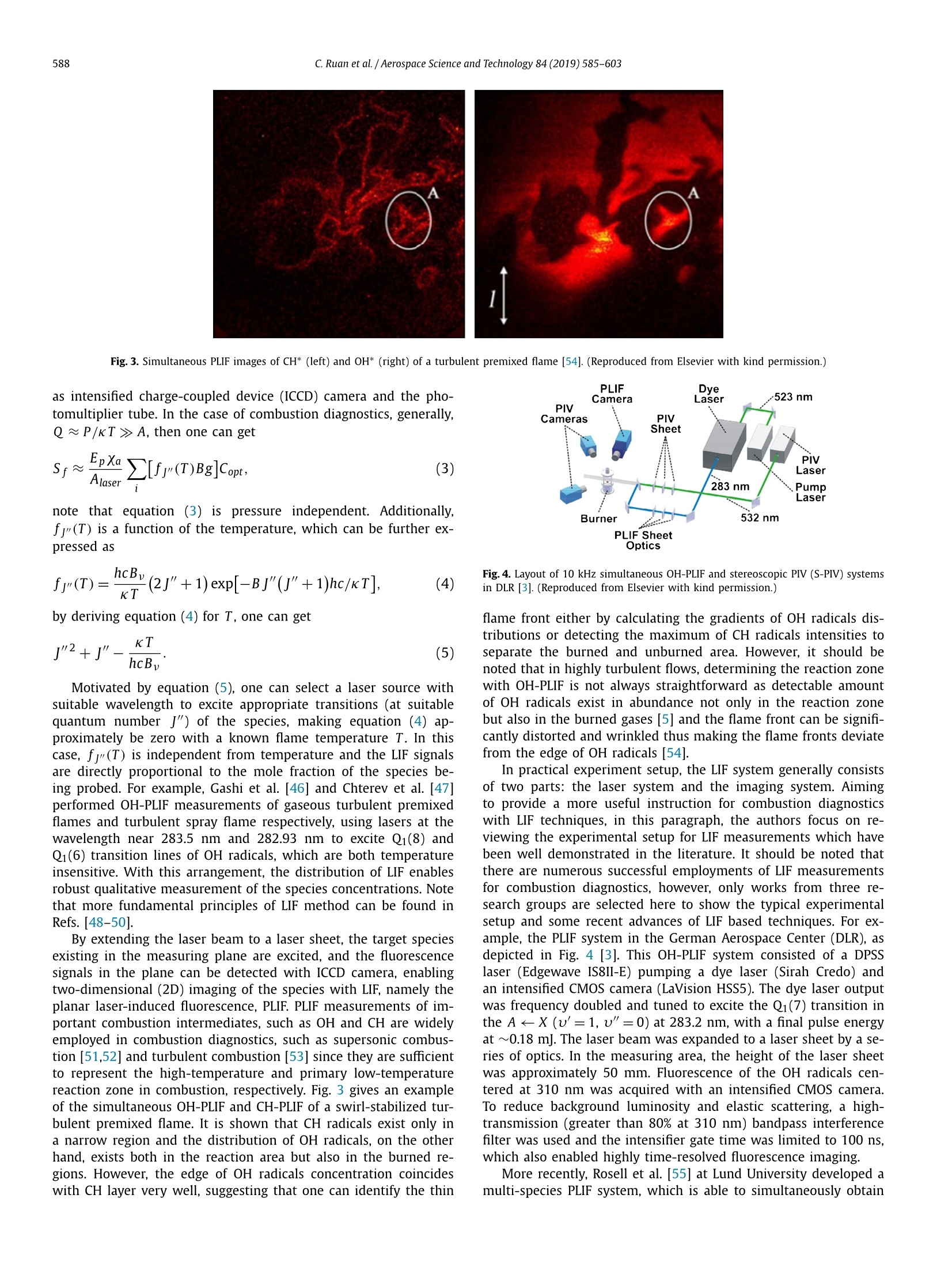
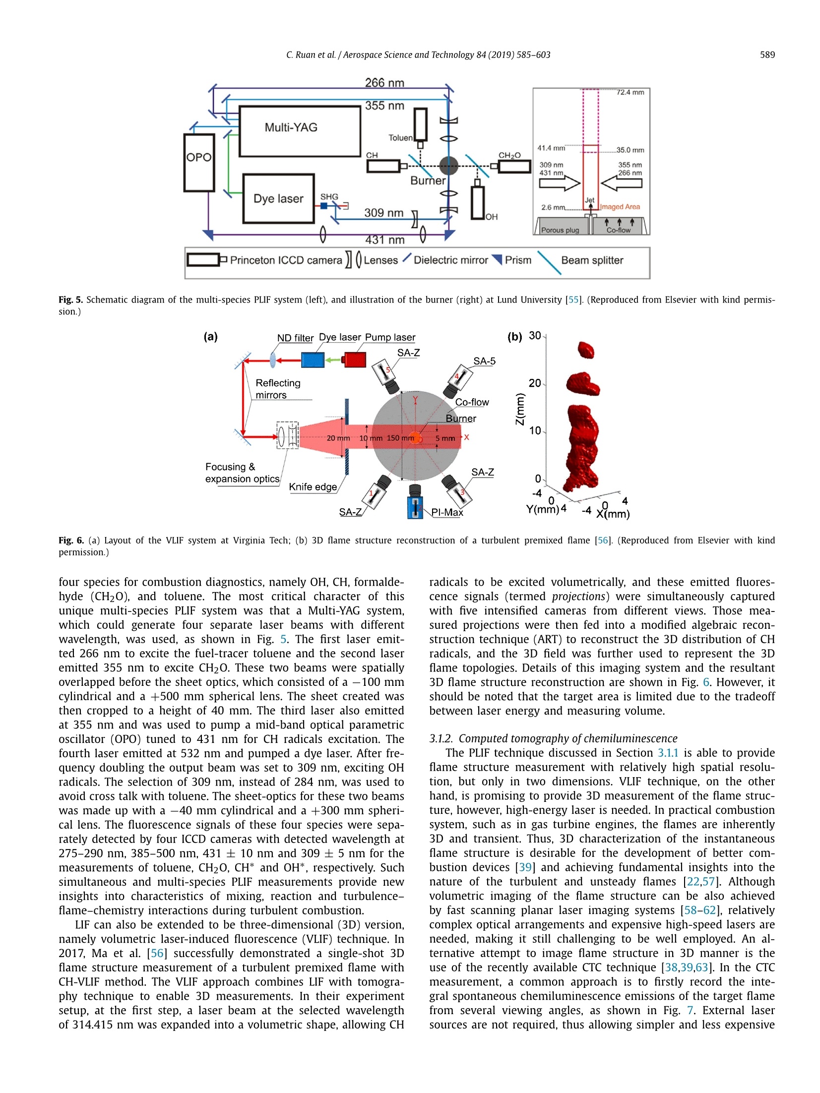
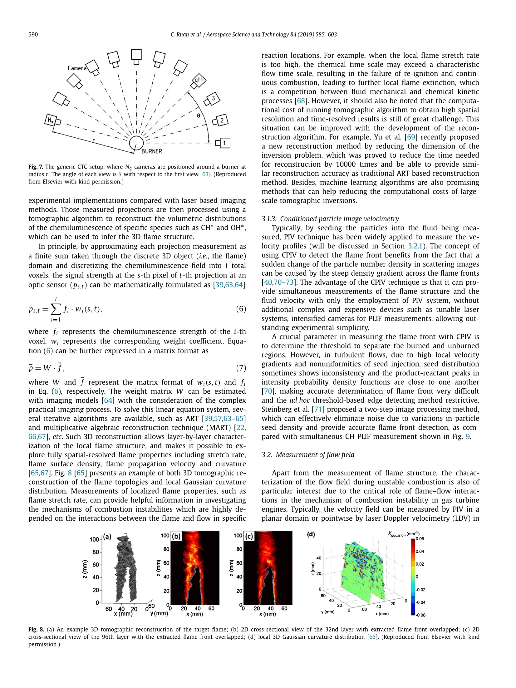
Aerospace Science and Technology 84 (2019) 585-603Aerospace Science and Technology 586C. Ruan et al. /Aerospace Science and Technology 84 (2019)585-603 Contents lists available at ScienceDirect ELSEVIER www.elsevier.com/locate/aescte Review Principles of non-intrusive diagnostic techniques and their applicationsfor fundamental studies of combustion instabilities in gas turbinecombustors: A brief review Can Ruan, Feier Chen, Weiwei Cai, Yong Qian, Liang Yu, Xingcai Lu* Key Laboratory for Power Machinery and Engineering of Ministry of Education, Shanghai Jiao Tong University, Shanghai 200240, PR China A BSTRACT Combustion instabilities are often manifested in modern fuel-lean gas turbine combustors. Investigatingthe mechanisms and developing control strategies for combustion instabilities in such systems areof practical importance and give rise to interesting scientific issues as large-amplitude pressure andheat release perturbations can lead to catastrophic and irreversible consequences on costly gas turbinehardware. In recent years, tremendous efforts have been made to achieve a deeper understanding ofthe periodic combustion oscillations in gas turbine engines with both advanced numerical simulationsand experimental diagnostics. In the latter case, state-of-the-art, non-intrusive diagnostic techniqueshave been well adopted to conduct fundamental studies on combustion instabilities in gas turbinemodel combustors. For example, simultaneous time-resolved measurements with planar laser-inducedfluorescence (PLIF) for characterizing flame structure and particle image velocimetry (PIV) for imagingflow field significantly contribute to the understanding of the role of flame-flow-acoustics coupling in theevents of combustion instabilities, and to the development and validation of advanced numerical models.However, planar measurements can be restrictive when flames are not axisymmetric or exhibit complexlarge-scale three-dimensional (3D) dynamics, which are commonly encountered in practical combustionsystem when combustion instabilities occur. Therefore, more recently, new volumetric imaging techniquesfor combustion diagnostics have attracted considerable research efforts. This paper categorizes differentadvanced non-intrusive combustion diagnostic techniques, including their basic principles and especiallyapplications for the study of combustion instability. Some of the recent progresses in the diagnostictechniques, such as computed tomography of chemiluminescence (CTC), volumetric laser inducedfluorescence (VLIF), rainbow-PIV, etc., are also discussed. These volumetric combustion diagnostictechniques offer the advantage to measure both spatial and temporal characteristics of the flame/flowof interest, which will enable deeper insights into the nature of unsteady combustion in the future. Thisbrief review is intended to be useful for both researchers and engineers to design and conduct furtherfundamental experiments on combustion instabilities in gas turbine engines. @ 2018 Elsevier Masson SAS. All rights reserved. 1. Introduction Diffusion-flame combustors have been traditionally favored ingas turbine engines for power generation and propulsion applica-tions for their reliable performance and reasonable stability char-acteristics [1]. Due to stricter exhaust emission regulations of gasturbine engines, new combustion concepts, such as lean premixedcombustion, with which the temperature in the combustion zoneis relatively low and hence thermal NOx emissions can be signif- ( * C orresponding author at: School of Mechanical Engineering, Shanghai Jiao Ton g U niversity, 800 Dongchuan Road, Shanghai 200240, PR C h ina. E -mail address: l yuxc@sjtu.edu.cn (X . Lu). ) icantly reduced, has been favored by modern gas turbine manu-factures [2-6]. However, one of the most critical issues limitingthe development of low-emission, lean premixed gas turbine en-gines is their susceptibility to combustion instabilities [7]. Thoseinstabilities are naturally excited by feedback loops that couple anacoustic mode of the engine with a process causing variations inthe rate of heat release from combustion [8]. The resultant large-amplitude pressure and heat release rate perturbations may leadto catastrophic and irreversible consequences on costly gas turbinehardware [9-11]. Therefore, it is of great importance to under-stand the mechanisms of the unstable combustion in fuel-lean gasturbine engine systems, thus allowing the development of robustcontrol strategies to achieve the desired level of flame stabilization. Over the past decades, both numerical and experimental ap-proaches have been extensively employed for the study of com-bustion instabilities in gas turbine engines. As for numerical sim-ulations, the capability of Large-eddy simulation (LES) to resolveunsteady characteristics during unstable combustion in (model) gasturbine engines has been demonstrated by several works. For ex-ample, Staffelbach et al.[12] and Wolf et al. [13,14] used massivelyparallel LES to investigate the azimuthal self-excited combustioninstability with a full annular combustor consisting of 15 burn-ers. Franzelli et al.[15] evaluated the effects of incomplete mixingbetween fuel and air on the characteristics of self-excited combus-tion instability by both LES and experiments, and results demon-strated that perfect premixing assumption was reasonable for sta-ble flows but was not acceptable to predict self-excited unstablecases. Han et al. [16] and Li et al. [17] successfully predicted thelimit cycle combustion instability by coupling LES with a low orderthermo-acoustic network, and the calculated limit cycle oscilla-tion frequency and normalized velocity amplitude were in goodagreement with the experimental values. Tachibana et al.[18] fur-ther stated the feasibility of applying LES in practical, liquid-fuelaero-engine combustor to the investigation of thermo-acoustic in-stability mechanisms. To conclude, LES has become one powerfultool to analyze combustion instabilities, however, due to the com-plexity of numerical simulation of combustion instability and highcomputational cost, it should be noted that LES is still not suffi-cient to fully analyze combustion instabilities. In the meantime, tremendous progress has been achieved in thedevelopment of non-intrusive combustion diagnostic techniques inrecent years, and results obtained with these techniques have con-tributed greatly to the current understanding of combustion [19].More specifically, experimental efforts regarding the combustioninstability have successfully identified the transient characteristicsduring unstable combustion in gas turbine combustors, includinglocal flame structures, flow field, species concentrations, tempera-ture, pressure, etc. For example, Stohr et al. [20] investigated un-steady interactions of flow, fuel-air mixing and reaction in a leanpartially-premixed turbulent swirl flame with simultaneous parti-cle image velocimetry (PIV) and planar laser-induced fluorescence(PLIF) of OH radicals and acetone at a repetition rate of 10 kHz,and they emphasized that the precessing vortex core (PVC) mighthave significant influence on the stabilization of the flame. Jeonget al. [21] also successfully characterized the interactions betweenthe flashback and combustion instability in a bluff-body stabilizedcombustor with the help of high-speed OH-PLIF and PIV measure-ments. By performing tomographic reconstruction of OH* chemi-luminescence, Worth and Dawson [22] elucidated the complexthree-dimensional (3D) dynamics of flame-flame and vortex-flameinteractions of two bluff-body stabilized flames excited by externalacoustics, to list a few. Such experimental results provide not onlynew insights into the coupling mechanisms between combustionand the resultant instabilities, but also useful well-documenteddata for the development and validation of advanced numericalmodels. The present work aims to provide a review of the principlesof the state-of-the-art, non-intrusive combustion diagnostic tech-niques, and their applications in the field of combustion instabilityresearches. The remainder of this work is organized as follows:this paper begins with a brief introduction of the dynamics andunderlying mechanisms of combustion instabilities in gas turbineengines, and then detailed principles of the selected diagnostictechniques which are capable of measuring important and essen-tial aspects of unstable combustion. This section is also accom-panied by some details for the experimental setup and emergingaspects of relevant diagnostic techniques, which are intended to beuseful for researchers and engineers to design and conduct furthercombustion instability investigations. A further section is dedicated to a survey of the applications of these advanced diagnostic tech-niques for the study of combustion instability, such as the imagingof flame-flow-acoustics interactions, measurement of the flametransfer function and active control of combustion instability viadiode-laser absorption spectroscopy. Finally, main conclusions aresummarized and potential challenges and issues with future re-search efforts are addressed. However, it should be noted that acomplete survey will be beyond the scope of this current paperbecause of the volume of literatures in both combustion diagnos-tics and combustion instabilities research areas. 2. Background knowledge of combustion instabilities Combustion instabilities refer to self-sustained combustion os-cillations at or near the acoustic frequency of the combustionchamber, and resultant high amplitude heat release rate and pres-sure oscillations have been encountered in many propulsion de-vices, such as rocket engines [23] and gas turbine engines [24],which generally exhibit high-frequency (order of kHz) and low-frequency (order of a few hundred Hz), respectively. Such instabili-ties are generally induced by the coupling between the acousticsand the heat release rate in the combustion chamber, and theamplification or attenuation of the pressure oscillation by heat ad-dition would occur if the periodic heat release rate is in or out ofphase with the pressure oscillation, as stated by the Rayleigh cri-terion [25], which can be formulated as where q’ is the volumetric heat fluctuation, p’ pressure fluctua-tion, V volume of interest, T period of the oscillation,Li i-th waveenergy dissipation process. This integral shows that the energy islocally transferred to the acoustic field when the phase shift be-tween the global heat release rate and the pressure oscillation isless than 90°, and when the total mechanical energy added to theoscillation by the heat addition process per cycle (left side) ex-ceeds the total energy dissipated by the oscillation per cycle (rightside), the combustion instability will be triggered and enhanced. Rayleigh criterion provides the critical knowledge of the roleof heat release rate and acoustic pressure coupling for the de-scription of self-excited combustion instability, more specifically,the assessment of the overall instability characteristics. However,it is still difficult to understand the detailed mechanism of self-excited combustion instability in practical combustion system andto develop robust control strategies to prevent the combustion os-cillations simply based on the Rayleigh criterion. It has been shownthat self-excited combustion instabilities in gas turbine engines areinduced by complex couplings between flow, flame and acoustics,and the heat release rate fluctuations act as the source energy ofthe acoustic field, leading to acoustic pressure and velocity fluc-tuations that propagate throughout the combustor. These acousticand flow field oscillations then in turn cause further heat releaserate oscillations. Consequently, a closed feedback loop is formed,and under some conditions, leads to the resonance between thecombustor and the acoustics, as shown in Fig. 1. There are several possible causes for heat release rate oscilla-tions in gas turbines, including fuel feed line acoustic coupling,equivalence ration oscillations, oscillatory atomization, oscillatoryflame area and vortex shedding, as have been summarized by Zinnand Lieuwen [27]. It is demonstrated that the underlying mech-anisms of the instabilities are based on the interaction betweenflow field, pressure, mixing and chemical reactions, however, thechemical and physical mechanisms driving these instabilities havenot been completely understood yet [6] and the prediction and Fig. 1. Schematic of the thermo-acoustic feedback loop [26]. (Reproduced from Else-vier with kind permission.) control of combustion instability in gas turbine engines is still ofgreat challenge, remaining a central issue in the design phase ofthe fuel-lean based ultra-low emission gas turbine engines. To explore the complex physical and chemical interplay in-volved in combustion instabilities and their influence on the com-bustion oscillations, it is of crucial importance to conduct reliableand multi-dimensional measurements of the highly transient andcomplex combustion processes in these unstable combustion sys-tems, which represents a major requirement for successful appli-cations of combustion diagnostic techniques for the study of com-bustion instability. In the next section, principles of some advancedand non-intrusive combustion diagnostic techniques, which areable to offer measurements of the temperature, reactant speciesof interest, flow field and flame structures, are presented. 3. Principles and experimental setup Traditionally, combustion diagnostics are based on techniqueswhere a mechanical probe is inserted directly into a region of in-terest, for example, the temperature in the combustion chambercan be measured with thermocouples, and the flow velocity canbe measured with a pitot tube or hot wire anemometry [19]. In-vasive combustion diagnostic approaches are widely used in prac-tical combustion testing situations, however, direct insertion of aprobe in the flame area can introduce undesirable, but unavoid-able disturbances into the original measurement field. Such localdisturbances include aerodynamic effects, flame quenching effects,thermal effects, catalytic effects, etc. [28], which will give rise tonon-negligible and different physical processes that increase themeasurement uncertainty. Motivated by the need to eliminate the disturbances induced bymeasurements with a mechanical probe, non-intrusive approachesfor combustion diagnostics were developed and great progresseshave been made in the past decades. For example, the flow fieldcan be quantified by laser Doppler velocimetry (LDV) [29] or PIV[30]; temperature by laser Rayleigh scattering [31], coherent anti-Stokes Raman scattering (CARS) [32], absorption spectroscopy [33],or laser induced fluorescence (LIF) [34]; species concentrations byLIF [35] or Raman scattering [36]; flame structures by planar LIF(PLIF) [37], computed tomography of chemiluminescence (CTC) [38,39] or conditioned-PIV (CPIV) [40]. In this paper, the authors arenot meant to review the principles of the whole non-intrusivetechniques, but rather concentrate on those which can be utilizedto obtain important parameters for the investigation of combus-tion instability, including LIF and CPIV for flame structure mea-surement, PIV for flow field quantification, Raman scattering andabsorption spectroscopy techniques for species concentration de-tection. New techniques, such as CTC, volumetric LIF, tomographicPIV, rainbow-PIV are also discussed. 3.1. Measurement of flame structure Combustion oscillations are featured by coupling of periodicheat release rate and acoustic pressure fluctuations. Meanwhile,the flame structure acts as the marker of the reaction area, which Fig.2. Schematic representation of A-X laser-induced fluorescence of transitionsbetween the grounded state (X) and the excited state(A) [44]. (Reproduced fromElsevier with kind permission.) involves complex chemical reactions and leads to further heat re-lease. A detailed characterization of the flame structure variationsduring unstable combustion, especially the response of the flameto the acoustics is essential not only for the understanding of fun-damental combustion process during oscillations but also for thecontrol of combustion instability. In this section, the principles andsome new aspects of techniques which are commonly applied todetect the flame structure are presented. It should be noted thatthe detection of the flame structure significantly depends on theproperties of the combustion process. As an example, CTC mea-surements are achieved by recording the chemiluminescence ofsome important intermediate species during combustion, such asOH*, CH*, and the spatially resolved chemiluminescence field ofthese intermediate species are then used to represent the reactionzone or the flame structure. 3.1.1. Laser-induced fluorescence First demonstrated in 1984 by Zare and Dagdigian [41], LIFtechnique, which is based on the resonant absorption-emissionprocess between laser photons and atoms or molecules, has beenwidely adopted in combustion diagnostics with the strength ofimaging capacity, high sensitivity, high spatial resolution, speciesspecificity and applicability in harsh environments [42]. The phys-ical principle of LIF can be simply summarized as absorption oftunable laser light by the molecule of interest creates an elec-tronically excited state, which then fluoresces [43], as schemat-ically shown in Fig. 2. In principle, a selected narrow spectralwidth laser is used to excite a chemical species of interest froma specific rotational-vibrational level in its ground state (X) to arotational-vibrational level in the excited electronic state (A). Theexcited species then undergoes a spontaneous transition back tothe ground electronic state, and the fluorescence is consequentlyemitted. These fluoresce signals, indicating the number of tar-geted atoms or molecules, are usually several orders of magnitudestronger than those obtained from Rayleigh scattering and Ramanscattering because of the resonant character of the excitation [19]and thus making LIF highly sensitive to the species being mea-sured. Generally, the intensity of LIF signal can be formulated as [45] where Ep is the energy of the laser pulse, Alaser the area of thelaser sheet, Xa the molar fraction of species being investigated,P pressure, K Boltzmann constant, T flame temperature, fr(T)the Boltzmann percentage of the absorption state at quantumnumber J", B Einstein absorption coefficient, g spectral overlapintegral, A effective spontaneous emission rate, Q sum of colli-sional quenching, Copt the efficiency of the detecting devices such Fig. 3. Simultaneous PLIF images of CH* (left) and OH* (right) of a turbulent premixed flame [54]. (Reproduced from Elsevier with kind permission.) as intensified charge-coupled device (ICCD) camera and the pho-tomultiplier tube. In the case of combustion diagnostics, generally,Q~P/KT> A, then one can get note that equation (3) isis pressure independent. Additionally,fj(T) is a function of the temperature, which can be further ex-pressed as by deriving equation (4) for T, one can get Motivated by equation (5), one can select a laser source withsuitable wavelength to excite appropriate transitions (at suitablequantum number J") of the species, making equation (4) ap-proximately be zero with a known flame temperature T. In thiscase, fj"(T) is independent from temperature and the LIF signalsare directly proportional to the mole fraction of the species be-ing probed. For example, Gashi et al. [46] and Chterev et al. [47]performed OH-PLIF measurements of gaseous turbulent premixedflames and turbulent spray flame respectively, using lasers at thewavelength near 283.5 nm and 282.93 nm to excite Qi(8) andQi(6) transition lines of OH radicals, which are both temperatureinsensitive. With this arrangement, the distribution of LIF enablesrobust qualitative measurement of the species concentrations. Notethat more fundamental principles of LIF method can be found inRefs. [48-50]. By extending the laser beam to a laser sheet, the target speciesexisting in the measuring plane are excited, and the fluorescencesignals in the plane can be detected with ICCD camera, enablingtwo-dimensional (2D) imaging of the species with LIF, namely theplanar laser-induced fluorescence, PLIF. PLIF measurements of im-portant combustion intermediates, such as OH and CH are widelyemployed in combustion diagnostics, such as supersonic combus-tion [51,52] and turbulent combustion [53] since they are sufficientto represent the high-temperature and primary low-temperaturereaction zone in combustion, respectively. Fig.3 gives an exampleof the simultaneous OH-PLIF and CH-PLIF of a swirl-stabilized tur-bulent premixed flame. It is shown that CH radicals exist only ina narrow region and the distribution of OH radicals, on the otherhand, exists both in the reaction area but also in the burned re-gions. However, the edge of OH radicals concentration coincideswith CH layer very well, suggesting that one can identify the thin Fig. 4. Layout of 10 kHz simultaneous OH-PLIF and stereoscopic PIV (S-PIV) systemsin DLR [3]. (Reproduced from Elsevier with kind permission.) flame front either by calculating the gradients of OH radicals dis-tributions or detecting the maximum of CH radicals intensities toseparate the burned and unburned area. However, it should benoted that in highly turbulent flows, determining the reaction zonewith OH-PLIF is not always straightforward as detectable amountof OH radicals exist in abundance not only in the reaction zonebut also in the burned gases [5] and the flame front can be signifi-cantly distorted and wrinkled thus making the flame fronts deviatefrom the edge of OH radicals [54]. In practical experiment setup, the LIF system generally consistsof two parts: the laser system and the imaging system. Aimingto provide a more useful instruction for combustion diagnosticswith LIF techniques, in this paragraph, the authors focus on re-viewing the experimental setup for LIF measurements which havebeen well demonstrated in the literature. It should be noted thatthere are numerous successful employments of LIF measurementsfor combustion diagnostics, however, only works from three re-search groups are selected here to show the typical experimentalsetup and some recent advances of LIF based techniques. For ex-ample, the PLIF system in the German Aerospace Center (DLR), asdepicted in Fig. 4 [3]. This OH-PLIF system consisted of a DPSSlaser (Edgewave IS8II-E) pumping a dye laser (Sirah Credo) andan intensified CMOS camera (LaVision HSS5). The dye laser outputwas frequency doubled and tuned to excite the Qi(7) transition inthe A
确定


还剩17页未读,是否继续阅读?

产品配置单


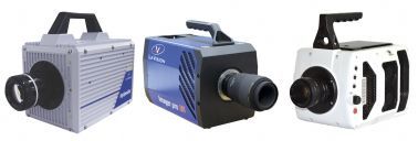
北京欧兰科技发展有限公司为您提供《燃气轮机中时间分辨OH-PLIF测量检测方案(CCD相机)》,该方案主要用于天然气/燃气中时间分辨OH-PLIF测量检测,参考标准--,《燃气轮机中时间分辨OH-PLIF测量检测方案(CCD相机)》用到的仪器有LaVision HighSpeedStar 高帧频相机、德国LaVision PIV/PLIF粒子成像测速场仪、PLIF平面激光诱导荧光火焰燃烧检测系统、LaVision DaVis 智能成像软件平台
推荐专场


相关方案
更多
该厂商其他方案
更多