


方案详情
文
采用LaVision公司的SprayMaster喷雾米氏散射成像测量和Artium公司的相位多普勒粒子干涉仪PDI对燃气轮机模型燃烧室液体单组分燃料贫爆的差异进行了测量和研究。
方案详情

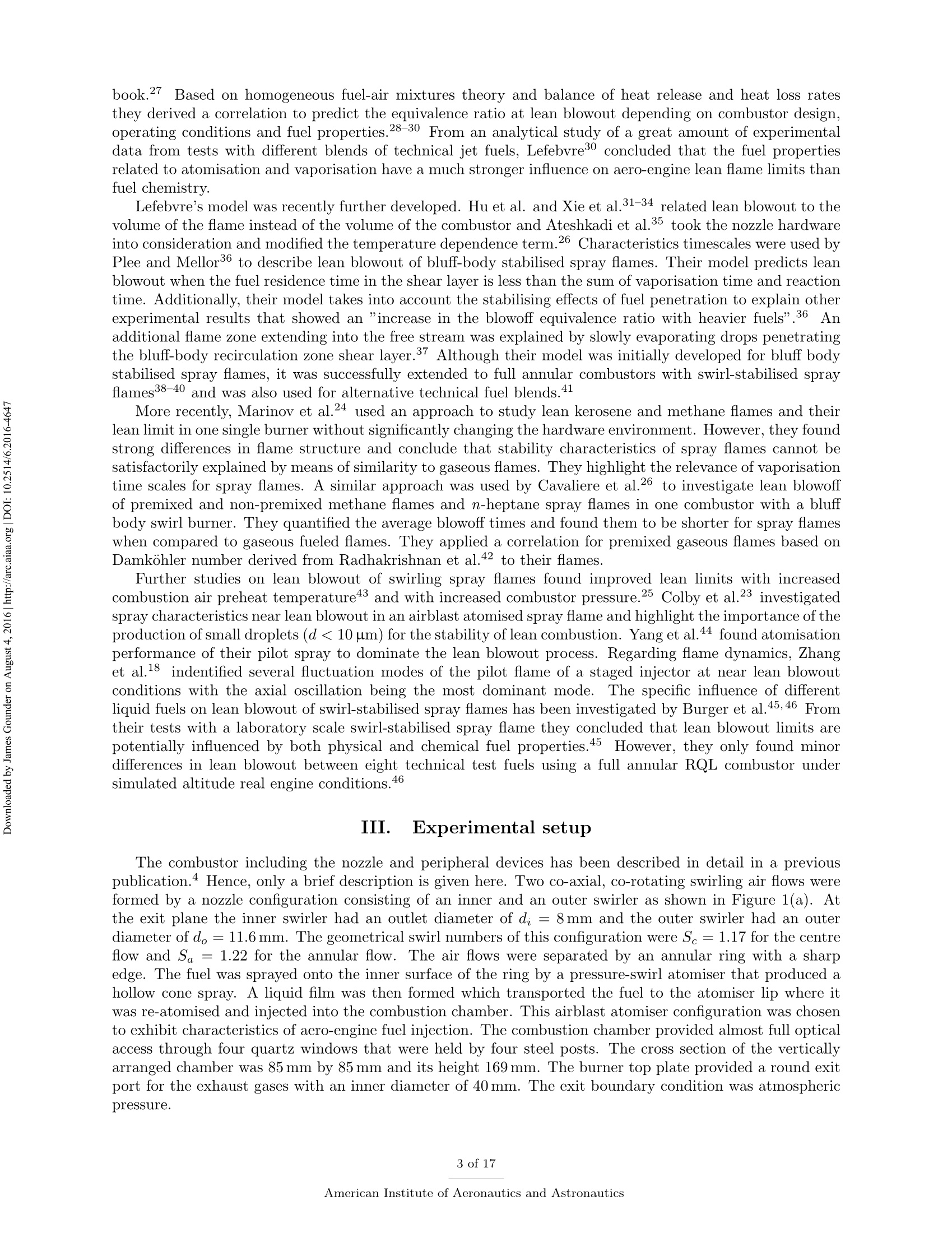
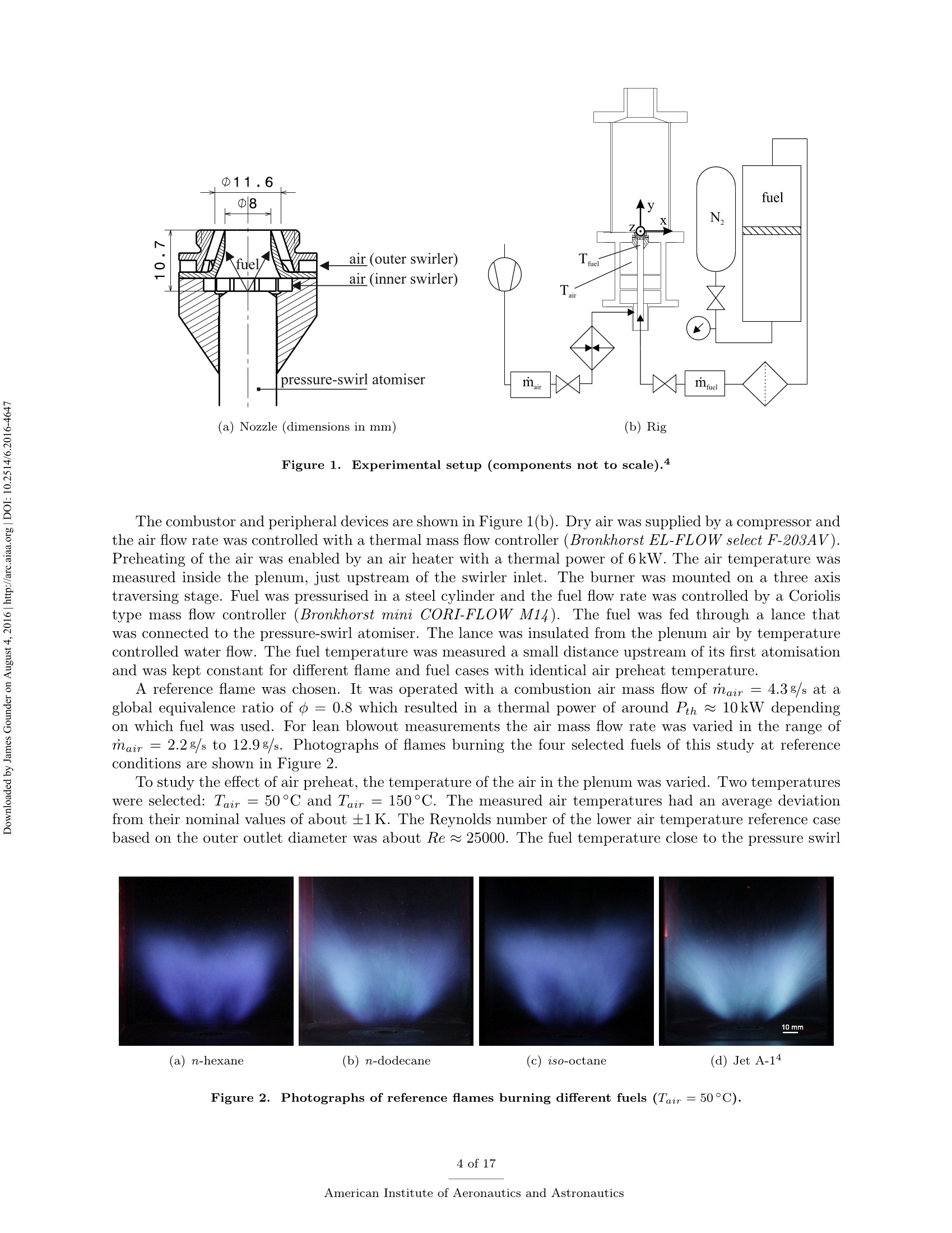
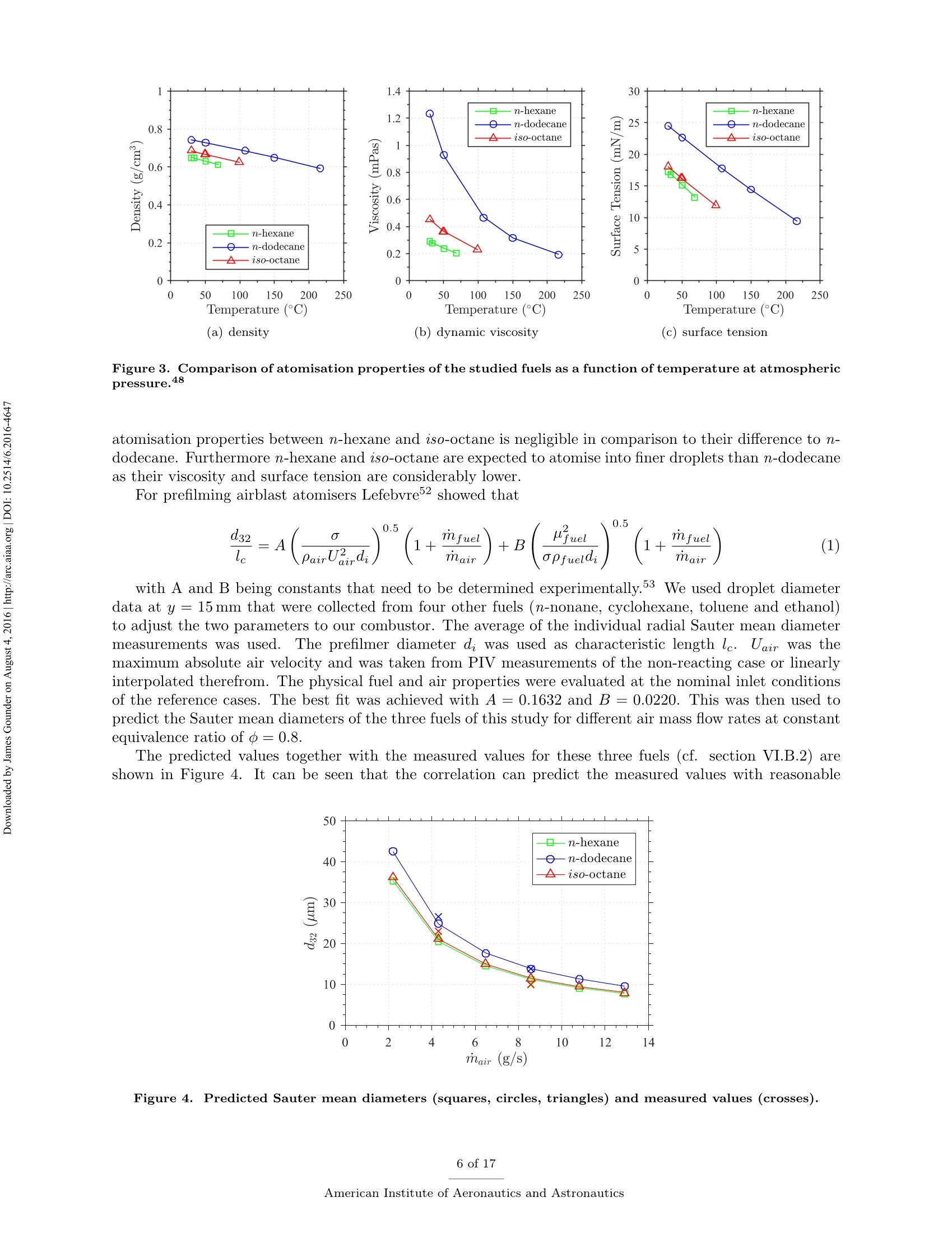
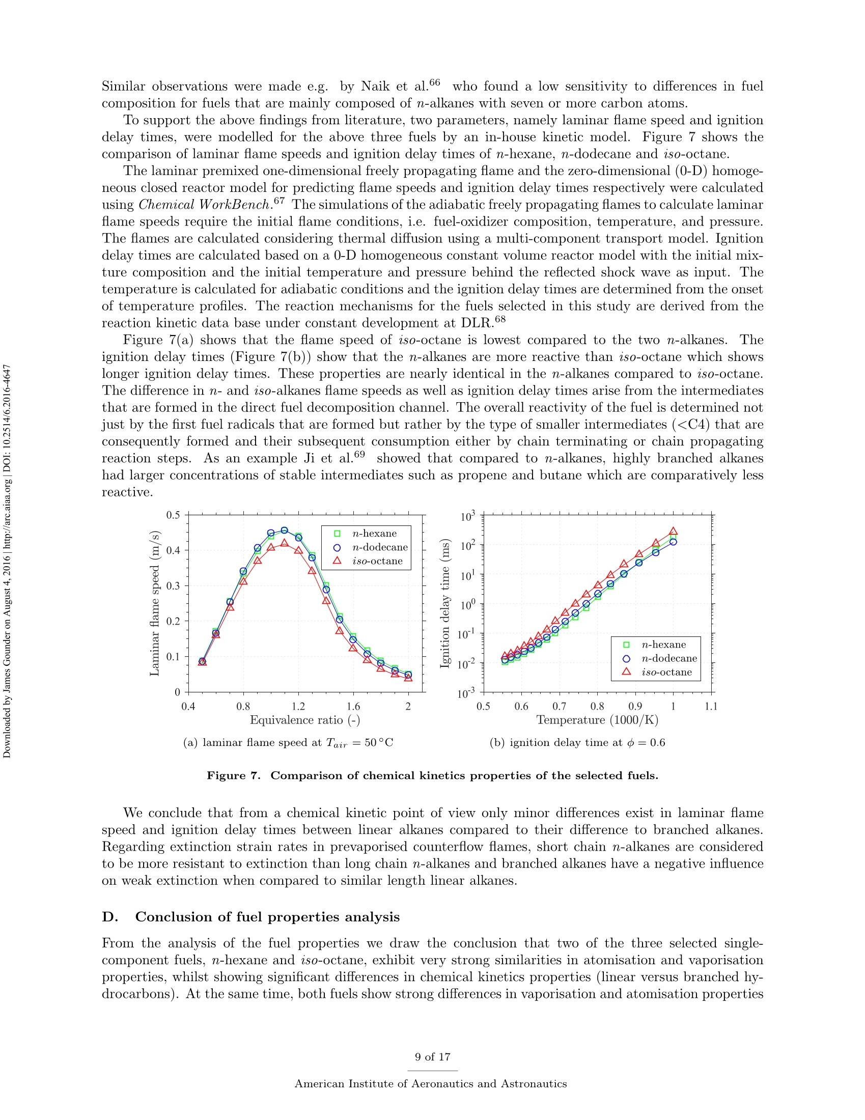
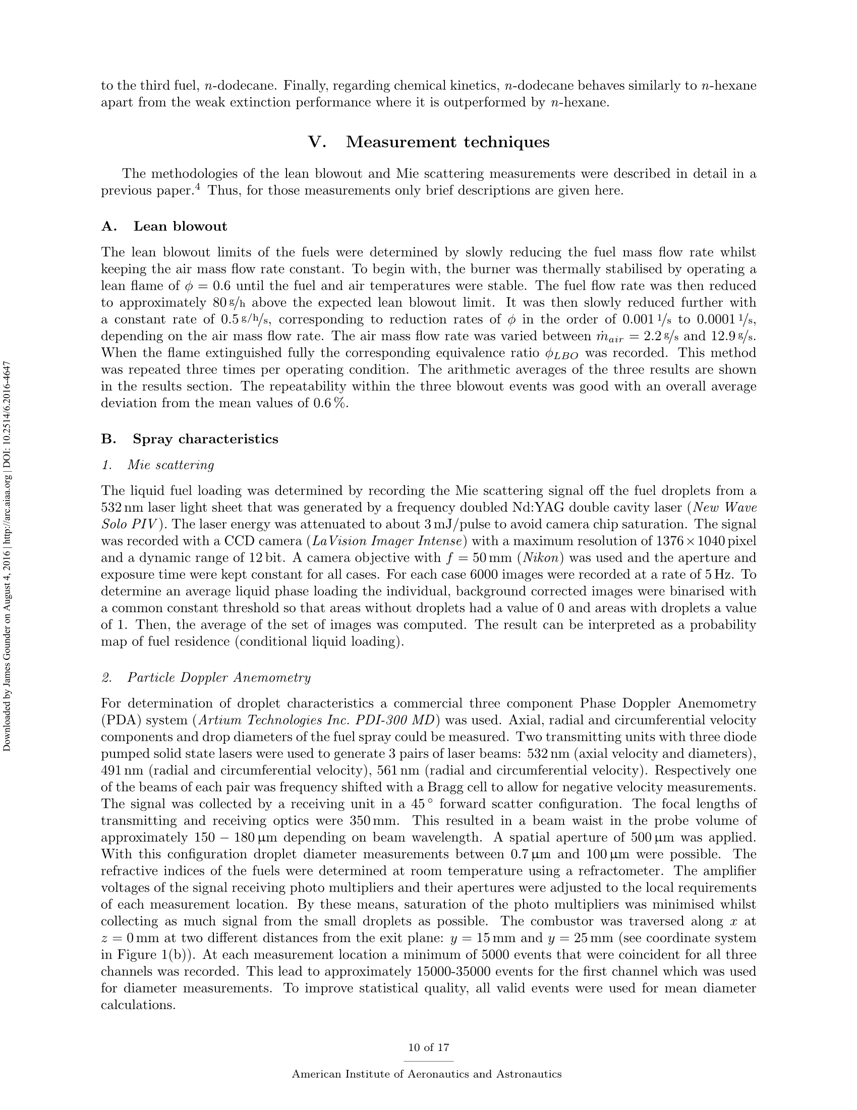
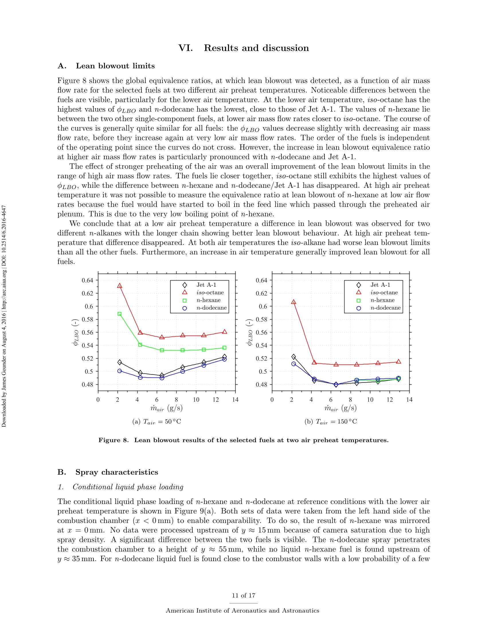
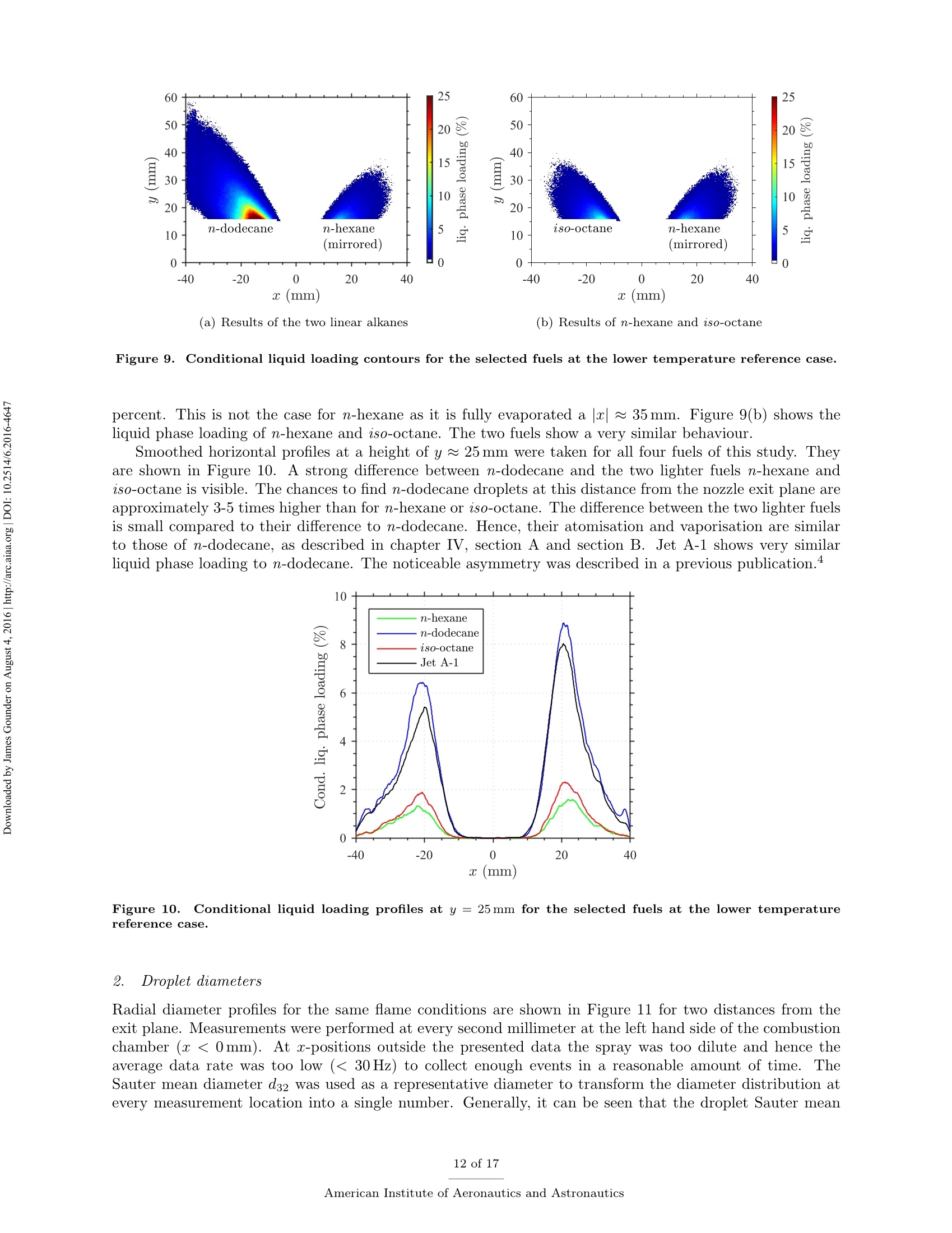
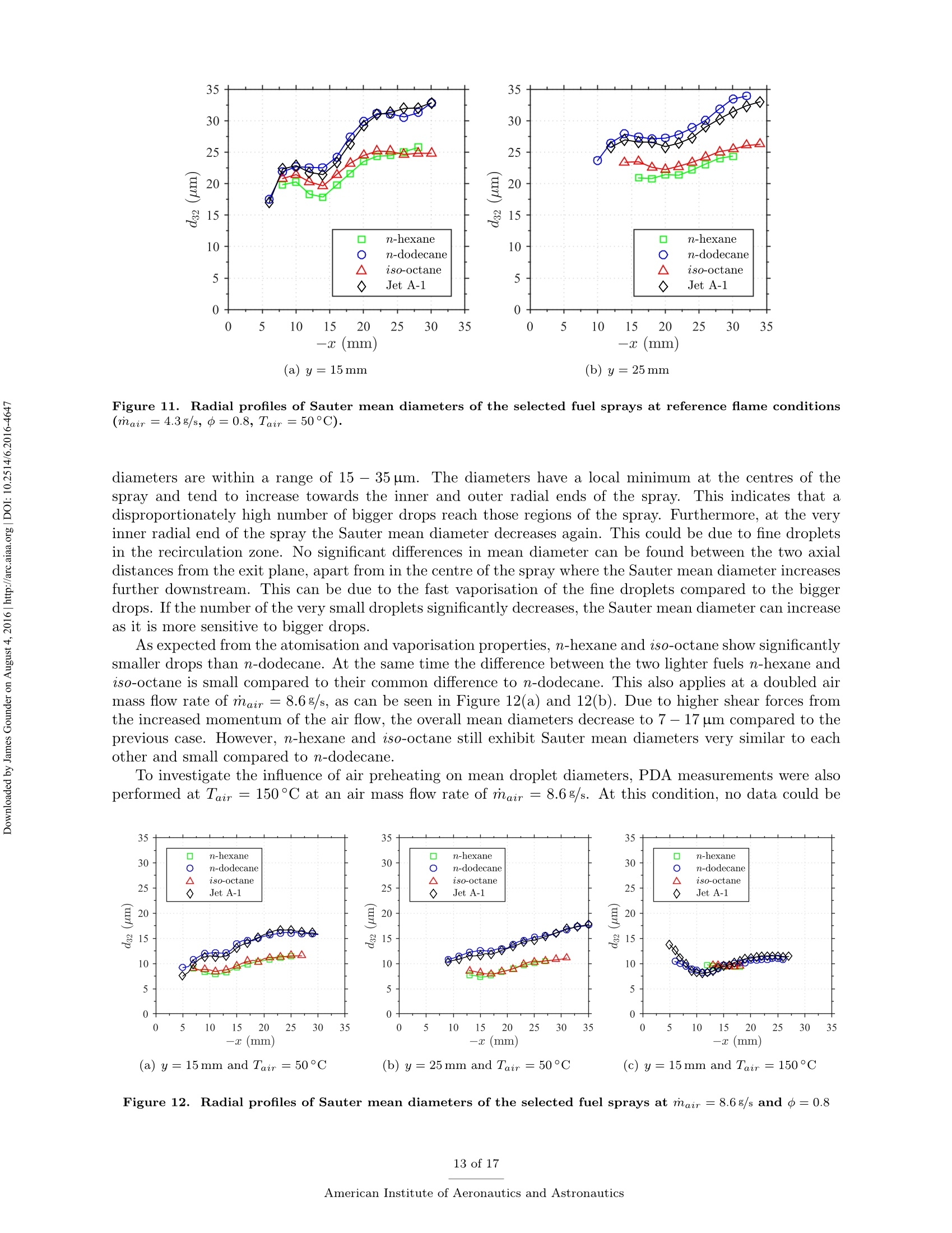
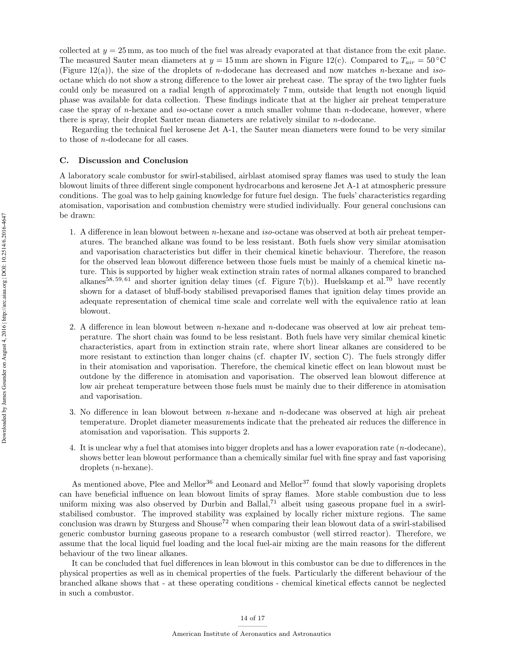
Propulsion and Energy ForumJuly 25-27, 2016, Salt Lake City, UT52nd AIAA/SAE/ASEE Joint Propulsion ConferenceCrossMarkclick for updates Investigation of differences in lean blowout of liquidsingle-component fuels in a gas turbine modelcombustor J. Grohmann, B. Rauch, T. Kathrotia, W. Meierand M. Aigner German Aerospace Center (DLR) Institute of Combustion Technology Pfoffenwaldring 38-40, 70569 Stuttgart, Germany The influence of selected single-component hydrocarbons on lean blowout behaviourof swirl-stabilised spray flames was investigated. Additional information on the spraycharacteristics was collected by Phase Doppler Anemometry (PDA) and Mie scatteringmeasurements. The measurements were accomplished in a gas turbine model combustorunder atmospheric pressure and at two different air preheat temperatures. The combustorfeatured a dual-swirl geometry and a prefilming airblast atomiser. The combustion chamberprovided good optical access and yielded well-defined boundary conditions. Three single-component hydrocarbons were chosen: one short and one long linear alkane (n-hexaneand n-dodecane) and one branched alkane (iso-octane). Kerosene Jet A-1 was used as atechnical reference. Results show noticeable differences in the lean blowout limits of thevarious fuels, at comparable flow conditions. By using the results of the measurements,of additional modelling and of an assessment of the fuel properties it was concluded thatfuel differences in lean blowout in this combustor can be due to differences in the physicalproperties as well as in the chemical properties. Nomenclature PDA Phase Doppler Anemometry LBO Lean blowout CFD Computational fluid dynamics RQL Rich quench lean TemperatureRS Thermal power Mass flow rate Reynolds number Geometrical swirl number Global equivalence ratio p,o,pi DIensity, surface tension, dynamic viscosity Prefilmer diameter Sauter mean diameter Initial drop diameter Total evaporation time Neff Effective evaporation rate 3,y,Z Reference coordinate system u, u, WVelocities in reference coordinate system *Research Associate, DLR, Institute of Combustion Technology, Stuttgart, Germany TResearch Associate, DLR, Institute of Combustion Technology, Stuttgart, Germany +Post-Doctorate, DLR, Institute of Combustion Technology, Stuttgart, Germany sSenior Scientist, DLR, Institute of Combustion Technology, Stuttgart, Germany ( Professor, DLR, Director of the I n stitute of C ombustion Technology, Stut t gart, G e rmany ) I. Introduction Production pathways for alternative aviation fuels offer the possibility to modify the chemical compo-sition of the final product in order to improve physical and chemical properties for optimised combustionperformance. Depending on feedstock (e.g. coal, natural gas or biomass) and process parameters, alternativefuels can contain hydrocarbons of significantly different types and chain lengths. However, the influence ofthe chemical composition of the fuel on combustion performance is not fully understood. Four main processes govern the combustion of liquid fuels in gas turbine combustors: atomisation, va-po isat on, tuurbulent mixing and chemical reaction. These processes happen simultaneously, have stronginteractions and cannot be easily independently measured in a technical combustor. They depend on differ-ent physical and chemical properties, show variable dependence on operating conditions, such as temperature,pressure, flow field and boundary conditions and vary with fuel composition. Because of this, a fuel variationis always a multi-parameter variation (e.g. in viscosity, boiling point and ignition delay time). For the designof fuels or fuel optimised combustors it is necessary to know whether the fuel properties that are related toa certain subprocess are at all relevant. Therefore it is important to be able to estimate the influence ofcertain fuel properties on a chosen combustion performance criterion (e.g. lean blowout). Particularly, therelative influence of a subprocess (relative compared to the influence of the other subprocesses) is of interest.This is a great challenge that needs input from experimental, theoretical and numerical studies. For this study a recently developed gas turbine model combustor was used to experimentally investigatethe influence of fuel variation on the lean blowout behaviour. Boundary conditions, such as air, fuel andwall temperatures, were well defined and measured in detail, as the collected data are also used for CFDvalidation.’The combustor setup exhibits characteristics of real aero-engines, i.e. airblast atomisation ofliquid fuel and a turbulent swirling flow field in a confined combustor. The experiments described in thiswork have been performed at atmospheric pressure. To reduce the additional complexity of the physical and chemical processes of multi-component fuels,single-component fuels have been used. Our goal is to gain a fundamental understanding of the influence ofthese fuels on a near-technical combustion system, before working on fuel mixtures or even fuel optimisation.Hence, experiments were performed with six fuels from the main four chemical classes of hydrocarbons(normal, branched and cyclic alkanes, and aromatics). For comparison kerosene Jet A-1 and ethanol wereused. The results of three single-component fuels (n-hexane, n-dodecane and iso-octane) are presented inthis publication, as well as the results for kerosene Jet A-1 which was used as a technical reference. The combustor and experimental setup have been presented in detail in a previous publication,4 as wellas its flow field, liquid fuel loading, flame luminosity and lean blowout behaviour for n-hexane, n-dodecaneand Jet A-1. Fuel differences were described but not interpreted in detail. This paper extends previousresults to the investigation ofa fourth fuel (iso-octane), spray characteristics measurements (Phase DopplerAnemometry) for all four fuels, a second air preheat temperature and a detailed discussion and comparison ofa wide range of relevant fuel properties. By taking advantage of similarities and differences in certain physicaland chemical properties of the selected fuels we aim to interpret differences in lean blowout behaviour. Tosupport the analysis, information from in-house vaporisation modelling and chemical kinetics modelling wereused. II..ILean blowout and fuel influence In the past, various aspects of spray combustion were studied using laboratory scale model combustorswith prefilming airblast atomisers, more or less similar to the one used in this study.5-22 The majority ofthe investigations used kerosene or a kerosene surrogate as a fuel. To the authors’ knowledge, the influenceof different single component hydrocarbon fuels on airblast atomised swirling spray flames, has not beeninvestigated in detail. This study investigates fuel influence on lean blowout behaviour of airblast atomisedswirling spray flames..There is general interest in understanding lean blowout as modern combustors areoperated under lean conditions to reduce emissions.23-25 In their reviews Cavaliere et al.26 and Marinov etal.24 show that a significant body of work regarding lean blowout of gaseous fueled swirling flames exists.However, lean blowout of spray flames has been studied in much less detail. Early work on spray flames was done by Lefebvre, Ballal and their co-workers and is summarised in their book.27 Based on homogeneous fuel-air mixtures theory and balance of heat release and heat loss ratesthey derived a correlation to predict the equivalence ratio at lean blowout depending on combustor design,operating conditions and fuel properties.28-30 From an analytical study of a great amount of experimentaldata from tests with different blends of technical jet fuels, Lefebvre30 concluded that the fuel propertiesrelated to atomisation and vaporisation have a much stronger influence on aero-engine lean flame limits thanfuel chemistry. Lefebvre’s model was recently further developed. Hu et al. and Xie et al.31-34 related lean blowout to thevolume of the flame instead of the volume of the combustor and Ateshkadi et al.35 took the nozzle hardwareinto consideration and modified the temperature dependence term.26 Characteristics timescales were used byPlee and Mellor36 to describe lean blowout of bluff-body stabilised spray flames. Their model predicts leanblowout when the fuel residence time in the shear layer is less than the sum of vaporisation time and reactiontime. Additionally, their model takes into account the stabilising effects of fuel penetration to explain otherexperimental results that showed an "increase in the blowoff equivalence ratio with heavier fuels”.36Anadditional flame zone extending into the free stream was explained by slowly evaporating drops penetratingthe bluff-body recirculation zone shear layer.37 Although their model was initially developed for bluff bodystabilised spray flames, it was successfully extended to full annular combustors with swirl-stabilised sprayflames38-40 and was also used for alternative technical fuel blends.41 More recently, Marinov et al.24 used an approach to study lean kerosene and methane flames and theirlean limit in one single burner without significantly changing the hardware environment. However, they foundstrong differences in flame structure and conclude that stability characteristics of spray flames cannot besatisfactorily explained by means of similarity to gaseous flames. They highlight the relevance of vaporisationtime scales for spray flames. A similar approach was used by Cavaliere et al.26 to investigate lean blowoffof premixed and non-premixed methane flames and n-heptane spray flames in one combustor with a bluffbody swirl burner. They quantified the average blowoff times and found them to be shorter for spray flameswhen compared to gaseous fueled flames. They applied a correlation for premixed gaseous flames based onDamkohler number derived from Radhakrishnan et al.42 to their flames. Further studies on lean blowout of swirling spray flames found improved lean limits with increasedcombustion air preheat temperature43 and with increased combustor pressure.25 Colby et al.23 investigatedspray characteristics near lean blowout in an airblast atomised spray flame and highlight the importance of theproduction of small droplets (d<10 um) for the stability of lean combustion. Yang et al.44 found atomisationperformance of their pilot spray to dominate the lean blowout process. Regarding flame dynamics, Zhanget a1.18indentified several fluctuation modes of the pilot flame of a staged injector at near lean blowoutconditions with the axial oscillation being the most dominant mode..The specific influence of differentliquid fuels on lean blowout of swirl-stabilised spray flames has been investigated by Burger et al.45,46 Fromtheir tessttss wwiitthh a laboratory scale swirl-stabilised spray flame they concluded that lean blowout limits arepotentially influenced by both physical and chemical fuel properties. However, they only found minordifferences in lean blowout between eight technical test fuels using a full annular RQL combustor undersimulated altitude real engine conditions.46 III.L。 Experimental setup The combustor including the nozzle and peripheral devices has been described in detail in a previouspublication.4 Hence, only a brief description is given here. Two co-axial, co-rotating swirling air flows wereformed by a nozzle configuration consisting of an inner and an outer swirler as shown in Figure 1(a). Atthe exit plane the inner swirler had an outlet diameter of di = 8 mm and the outer swirler had an outerdiameter of d。=11.6 mm. The geometrical swirl numbers of this configuration were Se=1.17 for the centreflow and Sa = 1.22 for the annular flow. The air flows were separated by an annular ring with a sharpedge. The fuel was sprayed onto the inner surface of the ring by a pressure-swirl atomiser that produced ahollow cone spray. A liquid film was then formed which transported the fuel to the atomiser lip where itwas re-atomised and injected into the combustion chamber. This airblast atomiser configuration was chosento exhibit characteristics of aero-engine fuel injection. The combustion chamber provided almost full opticalaccess through four quartz windows that were held by four steel posts. The cross section of the verticallyarranged chamber was 85 mm by 85 mm and its height 169 mm. The burner top plate provided a round exitport for the exhaust gases with an inner diameter of 40 mm. The exit boundary condition was atmosphericpressure. (a) Nozzle (dimensions in mm) (b) Rig Figure 1. Experimental setup (components not to scale). The combustor and peripheral devices are shown in Figure 1(b). Dry air was supplied by a compressor andthe air flow rate was controlled with a thermal mass flow controller (Bronkhorst EL-FLOW select F-203AV).Preheating of the air was enabled by an air heater with a thermal power of 6kW. The air temperature wasmeasured inside the plenum, just upstream of the swirler inlet. The burner was mounted on a three axistraversing stage. Fuel was pressurised in a steel cylinder and the fuel flow rate was controlled by a Coriolistype mass flow controller (Bronkhorst mini CORI-FLOW M14). The fuel was fed through a lance thatwas connected to the pressure-swirl atomiser. The lance was insulated from the plenum air by temperaturecontrolled water flow. The fuel temperature was measured a small distance upstream of its first atomisationand was kept constant for different flame and fuel cases with identical air preheat temperature. A reference flame was chosen. It was operated with a combustion air mass flow of mair=4.3 g/s at aglobal equivalence ratio of =0.8 which resulted in a thermal power of around Pth~ 10kW dependingon which fuel was used. For lean blowout measurements the air mass flow rate was varied in the range ofmair = 2.2g/s to 12.9g/s. Photographs of flames burning the four selected fuels of this study at referenceconditions are shown in Figure 2. To study the effect of air preheat, the temperature of the air in the plenum was varied. Two temperatureswere selected: Tair =50°C and Tair =150°C. The measured air temperatures had an average deviationfrom their nominal values of about ±1K. The Reynolds number of the lower air temperature reference casebased on the outer outlet diameter was about Re~25000. The fuel temperature close to the pressure swirl Figure 2. Photographs of reference flames burning different fuels (Tair=50°C). atomiser outlet was kept constant at Tfuel = 30°C for the lower air temperature and at Tfuel = 50°C forthe higher air temperature. Due to strong heat transfer from the plenum air into the fuel lance, the fueltemperature for the higher air temperature test could not be kept at the same level as for that with the lowerair temperature. However it was kept constant for variations in air mass flow rate, equivalence ratio andfuel in the respective cases. The measured fuel temperatures had an average deviation from their nominalvalues of about ±1 K for the lower temperature case and about ±5 K for the higher temperature case. IV.. sSelected fuels for this study and their properties Three single-component hydrocarbons were selected for this study: n-hexane,n-dodecane and iso-octane.They had a purity greater than 99%.. n-Hexane and n-dodecane represent short and long linear alkanesand iso-octane (2,2,4-trimethylpentane) is a representative for the branched alkanes. FFor comparison allmeasurements were also performed with kerosene Jet A-1 as a reference. As indicated above, the global equivalence ratio and the air mass flow rate were kept constant to definereference conditions for all fuels. As a result the thermal power, the fuel mass flow rate and the adiabaticflame temperature differed between the various fuel cases. Such differences are unavoidable when comparingfuels. However, for the chosen fuels of this study, the differences are relatively small. Table 1 shows thevalues of these four parameters for the selected fuels at reference conditions. The equivalence ratio of theJet A-1 was calculated based on its average C:H ratio. n-hexane n-dodecane iso-octane Jet A-1 0.8 0.8 0.8 0.8 Pth 10.12kW 10.12kW 10.10kW 10.22kW mfuel 814.1g/h 826.3g/h 820.1g/h 850.0g/h Tad 2065.2K 2069.6K 2067.4K n.a. Table 1. Flame parameters of the studied fuels at reference conditions. Some of the thermodynamic properties, e.g. the heat capacity, are usually declared per quantity of fuel.This can be achieved on a mass or a molar basis. Depending on the relative size differences of the molecules,this can lead to different fuel rankings. However, as shown in Table 1, the fuel mass flow rates at comparableequivalence ratios are relatively close to each other. Furthermore, the comparison of lean blowout behaviouris done on an equivalence ratio basis.. Therefore we consider the mass specific quantities to be relevant forfuel comparisons in this study. In the following sections we look at process relevant physical and chemical properties of the selected fuels.Most of the properties depend on temperature (and also pressure) and on its way from initial atomisation tofinal combustion the fuel is exposed to a variety of temperatures. Hence, characteristic fuel properties needto be compared at different temperatures as their relative difference might be temperature dependent as well.As all experiments were performed at atmospheric pressure, the influence of pressure on the physical andchemical properties was not addressed. The fuel properties data were taken from the ThermoData Engine(TDE),47-49 version 2.1, if not stated otherwise. A. Atomisation properties Three physical fuel parameters are commonly known to have an impact on atomisation quality of a liquidfuel: density, viscosity and surface tension. Figure 3 shows their temperature dependence for the three single-component fuels of this study for a temperature range between Tfuel =30°C and their respective boilingpoint. Two main conclusions can be drawn. Firstly, the lines show no intersections at any temperature.Hence, whatever the impact of one of the parameters on atomisation is, their fuel related order is independentof the temperature. This means we do not expect one fuel to have a much different atomisation performancerelative to another fuel at low temperature than at high temperature. Secondly, the properties of n-hexane and iso-octane lie considerably closer to each other than to thelong linear alkane n-dodecane. This is particularly apparent for dynamic viscosity and surface tension whichare known to have a strong impact on prefilming airblast atomisation, compared to liquid density which isconsidered to have little effect on mean drop size.50-53Therefore it can be concluded that the difference in Figure 3. Comparison of atomisation properties of the studied fuels as a function oftemperature at atmosphericpressure.48 atomisation properties between n-hexane and iso-octane is negligible in comparison to their difference to n-dodecane. Furthermore n-hexane and iso-octane are expected to atomise into finer droplets than n-dodecaneas their viscosity and surface tension are considerably lower. For prefilming airblast atomisers Lefebvre showed that with A and B being constants that need to be determined experimentally.53 We used droplet diameterdata at y=15 mm that were collected from four other fuels (n-nonane, cyclohexane, toluene and ethanol)to adjust the two parameters to our combustor. The average of the individual radial Sauter mean diametermeasurements was used. The prefilmer diameter di was used as characteristic length le. Uair was themaximum absolute air velocity and was taken from PIV measurements of the non-reacting case or linearlyinterpolated therefrom. The physical fuel and air properties were evaluated at the nominal inlet conditionsof the reference cases. The best fit was achieved with A=0.1632 and B =0.0220. This was then used topredict the Sauter mean diameters of the three fuels of this study for different air mass flow rates at constantequivalence ratio ofo=0.8. The predicted values together with the measured values for these three fuels (cf. section VI.B.2) areshown in Figure 4.It can be seen that the correlation can predict the measured values with reasonable Figure 4. Predicted Sauter mean diameters (squares, circles, triangles) and measured values (crosses). accuracy and that the expectation of n-hexane and iso-octane performing very similarly in atomisation andn-dodecane atomising into bigger drops is confirmed. Note, that the diameter data were collected at reactingconditions but the influence of vaporisation was neglected here. B. Vaporisation properties The evaporation process is influenced by a multitude of thermodynamical properties (vapour pressure, en-thalpy of vaporisation, specific heat capacity, heat conductivity, to name a few) and process properties (suchas pressure, temperature, relative velocity of the droplet to the gas flow, species concentration in the gasfield). To gain a first understanding of the differences in the fuel evaporation behaviour, the boiling pointsare compared in Table 2.. One can see that the boiling points of n-hexane and iso-octane are relativelysimilar and the boiling point of n-dodecane is twice as high. Boiling point Table 2. Boiling points of the studied fuels at atmospheric pressure.54 This is also reflected in the evolution of the vapour pressure with temperature as reported in Figure 5(a).In consequence one can assume a similar evaporation behaviour of n-hexane and iso-octane. In contrast, theenthalpy of vaporisation does not show the same tendencies (see Figure 5(b)). At low intermediate liquidtemperatures n-hexane has the highest enthalpy of vaporisation, which slows down the evaporation process. To quantitatively analyse the differences in the evaporation processes the effective evaporation rate Xeffas defined by Lefebvre27 is used. te is the total evaporation time (including droplet heating up) and do is the initial diameter. The effective evaporation rate was also considered by Lefebvre as one of the influencing parameters on LBO."The in-house code Spraysim was used to compute the effective evaporation rates. It is a simulation tool de-veloped at the DLR, Institute of Combustion Technology, for spray systems found in premixing/prevaporisingmodules and gas turbine combustors and has been described in previous publications (e.g. by Rauch et al.5).The evaporation model is based on the model of Abramzon and Sirignano56 and extended to multicomponentfuels. The high reliability and accuracy of the evaporation model was shown in several validation studies.55,57Figure 6 shows the effective evaporation rate for all fuels in comparison. The initial air temperature wasvaried. One can see, that the effective evaporation rates of n-hexane and iso-octane are practically the Figure 5. Comparison of vaporisation properties of the studied fuels as a function of temperature at atmo-spheric pressure.48 same over the whole temperature range. This surpasses the initial hypothesis based on the thermodynamicproperties of the fuels that the difference in vaporisation of n-hexane and iso-octane is small compared totheir difference to n-dodecane. To compute the evaporation rate, the initial conditions of the droplets werethe same for all fuels with an initial diameter of do = 30 um, a constant initial liquid phase temperature ofTiig,o =30°C and an initial relative velocity between air and droplets of Urel,0=2m/s. In reality these mightbe slightly different between fuels and depend on the type of fuel and preceding processes. Figure 6. Evolution of the effective evaporation rate as function of ambient gas temperature. Initial diameter,temperature and relative velocity of the droplet were the same for all fuels. C..Chemical kinetics properties Several characteristics are usually used to describe the chemical kinetic properties of fuels. Among thoseare laminar flame speed, ignition delay time and extinction strain rate. In a series of experiments Holley etal.58-60 determined extinction strain rates of a wide range of single-component hydrocarbons and technicaljet fuels. The fuels were prevaporised in a heated nitrogen flow before a non-premixed planar counterflowflame was established. The fuel flow rate was then reduced until extinction occurred and the maximumstrain rate was measured just before the extinction event. They found the weak extinction strain rates ofn-heptane to exceed those of iso-octane for a wide range of equivalence ratios58 and found n-octane flames tobe more resistant to extinction than iso-octane flames.59 Implications of these results for flame stability wereconcluded and the importance of branched alkanes on the flame response was highlighted. When comparinglinear alkanes they found those with smaller carbon numbers to have greater resistance to extinction thanthose with longer carbon chains, which was explained by molecular mass diffusivity.60 In a similar setupWon et al.61 found iso-octane to have notably poorer extinction strain rates than a set of n-alkanes rangingbetween 7 and 10 in carbon number. When compared on a fuel mass fraction basis they also found thehighest extinction resistance with the shortest n-alkane. When validating a detailed chemical reaction mechanism of n-alkanes from n-octane to n-hexadecane,Westbrook et a1.62 found that ignition delay times at higher temperatures and species profiles of a jet stirredreactor of the n-alkanes are very similar. They concluded that those n-alkanes are sufficiently similar thatthey can be exchanged among each other in many application simulations. In their literature review theyalso mentioned that straight chain hydrocarbons are more easily ignited under (piston) engine conditionsthan branched hydrocarbons. The similarity in ignition delay times of higher n-alkanes was also confirmedby Davidson et al.63 at temperatures above 1250 K. Li et al.64 used shock tube measurements to determineignition delay times of three branched alkanes. In their literature review they list a wide range of previousstudies that have found generally lower reactivity of branched alkanes compared to linear alkanes.Bycomparing their data to ignition delay times of linear alkanes they could confirm that an increase in thedegree of carbon chain branching increases the ignition delay times. From a review of laminar flame speed measurements and corresponding modelling Ranzi et al.655con-cluded that laminar flame speeds of linear alkanes with carbon numbers of four or more are nearly identical.Branched hydrocarbons however, have lower burning velocities than their corresponding normal component. Similar observations were made e.g.by Naik et al.66 who found a low sensitivity to differences in fuelcomposition for fuels that are mainly composed of n-alkanes with seven or more carbon atoms. To support the above findings from literature, two parameters, namely laminar flame speed and ignitiondelay times, were modelled for the above three fuels by an in-house kinetic model. Figure 7 shows thecomparison of laminar flame speeds and ignition delay times of n-hexane, n-dodecane and iso-octane. The laminar premixed one-dimensional freely propagating flame and the zero-dimensional (0-D) homoge-neous closed reactor model for predicting flame speeds and ignition delay times respectively were calculatedusing Chemical WorkBench.7 The simulations of the adiabatic freely propagating flames to calculate laminarflame speeds require the initial flame conditions, i.e. fuel-oxidizer composition, temperature, and pressure.The flames are calculated considering thermal diffusion using a multi-component transport model. Ignitiondelay times are calculated based on a 0-D homogeneous constant volume reactor model with the initial mix-ture composition and the initial temperature and pressure behind the reflected shock wave as input. Thetemperature is calculated for adiabatic conditions and the ignition delay times are determined from the onsetof temperature profiles. The reaction mechanisms for the fuels selected in this study are derived from thereaction kinetic data base under constant development at DLR.68 Figure 7(a) shows that the flame speed of iso-octane is lowest compared to the two n-alkanes.Theignition delay times (Figure 7(b)) show that the n-alkanes are more reactive than iso-octane which showslonger ignition delay times. These properties are nearly identical in the n-alkanes compared to iso-octane.The difference in n- and iso-alkanes flame speeds as well as ignition delay times arise from the intermediatesthat are formed in the direct fuel decomposition channel. The overall reactivity of the fuel is determined notjust by the first fuel radicals that are formed but rather by the type of smaller intermediates (
确定


还剩15页未读,是否继续阅读?

产品配置单
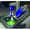


北京欧兰科技发展有限公司为您提供《燃气轮机模型燃烧室中燃料喷雾液滴粒径检测方案(激光粒度仪)》,该方案主要用于天然气/燃气中燃料喷雾液滴粒径检测,参考标准--,《燃气轮机模型燃烧室中燃料喷雾液滴粒径检测方案(激光粒度仪)》用到的仪器有LaVision SprayMaster inspex 喷雾成像测量系统、激光相位多普勒干涉仪LDV,PDI,PDPA,PDA、LaVision DaVis 智能成像软件平台
推荐专场


相关方案
更多
该厂商其他方案
更多