


方案详情
文
采用LaVision的时间分辨体视层析粒子成像测速系统(TRTOMO-PIV)对低速湍流边界层中流场的相干结构进行了详细讨论和研究。
方案详情

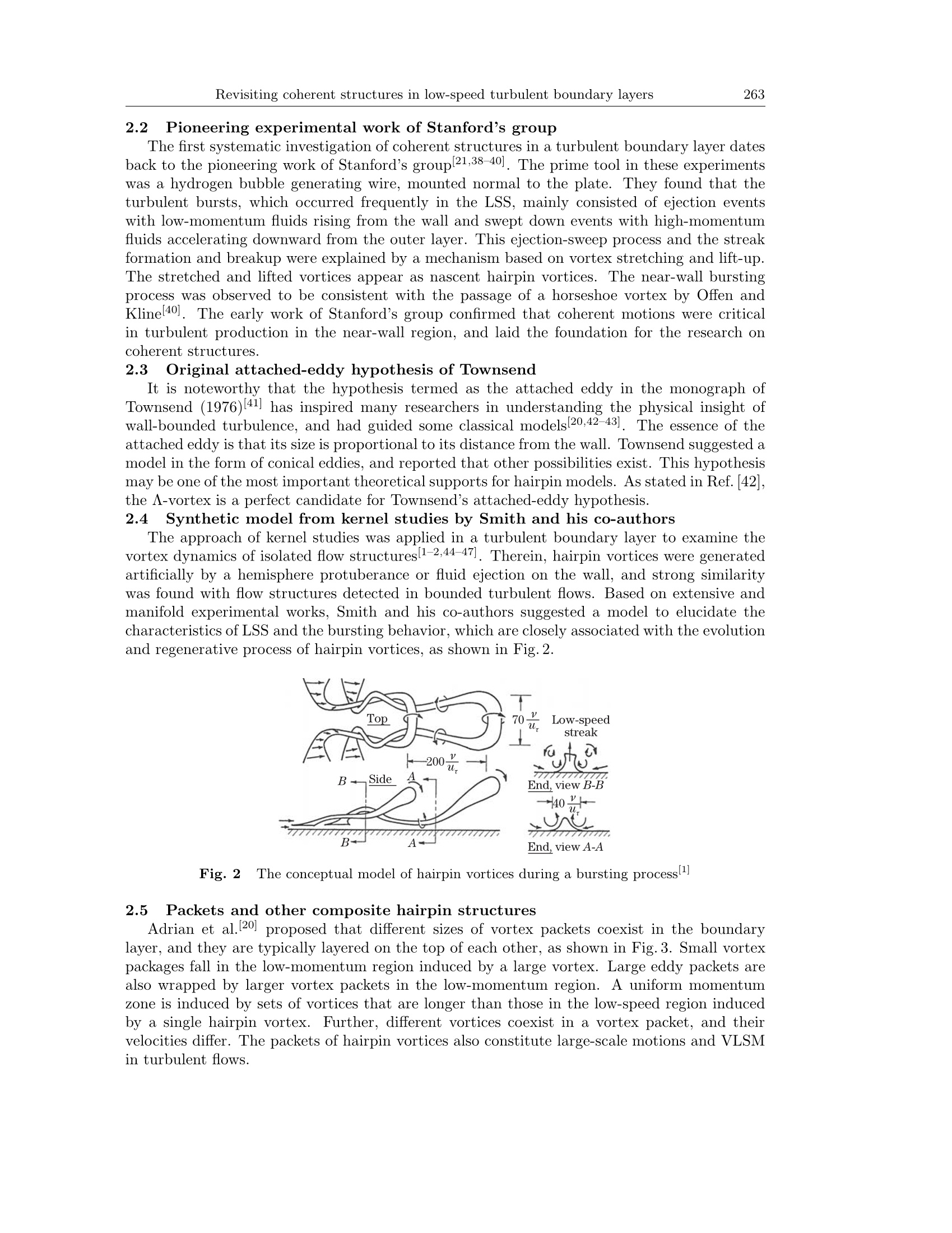
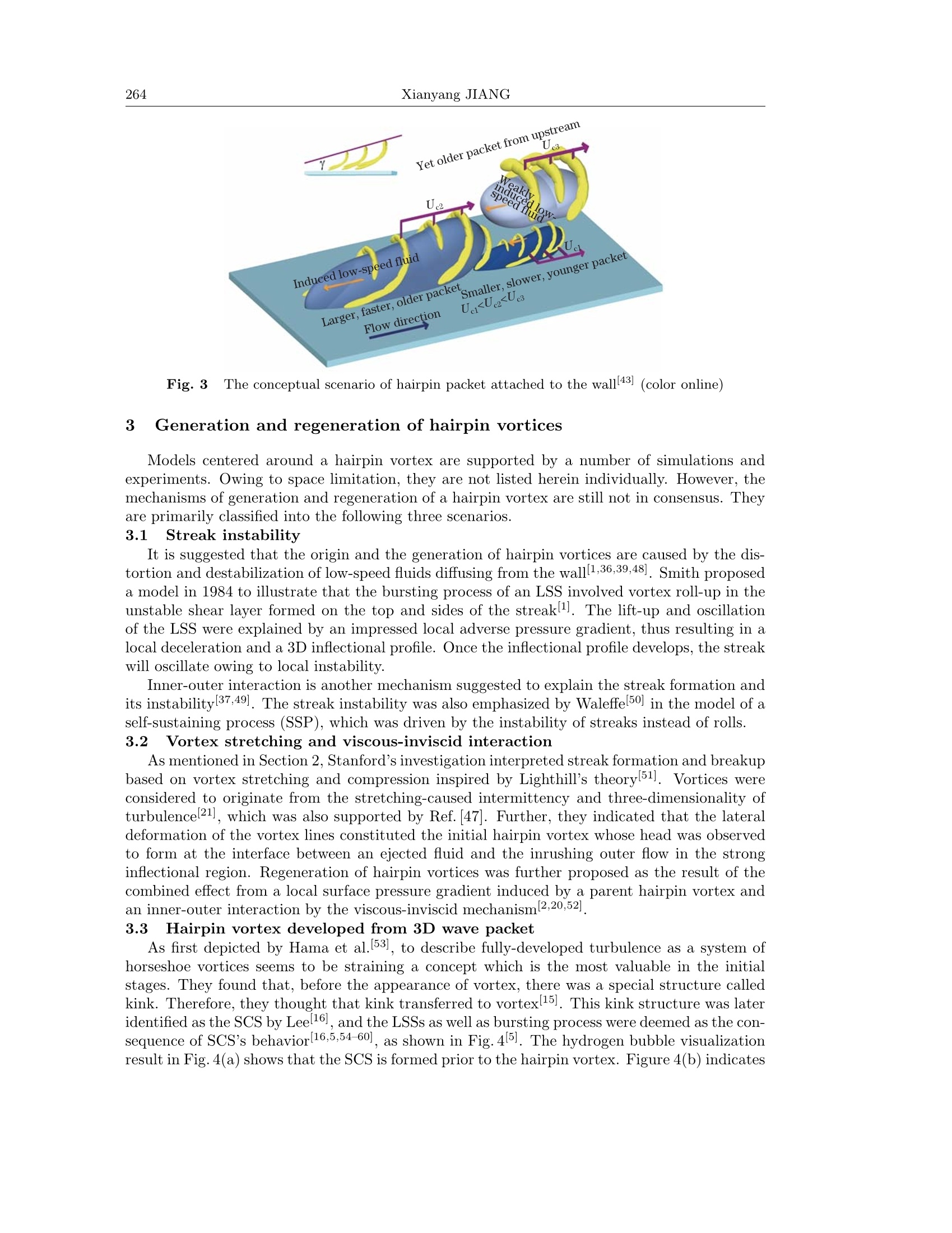
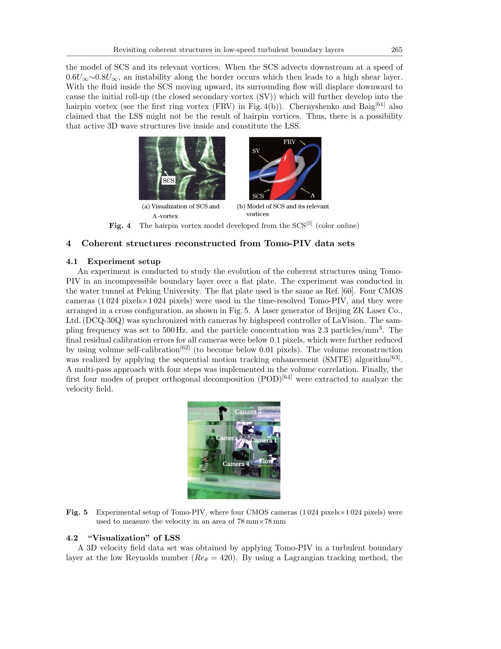
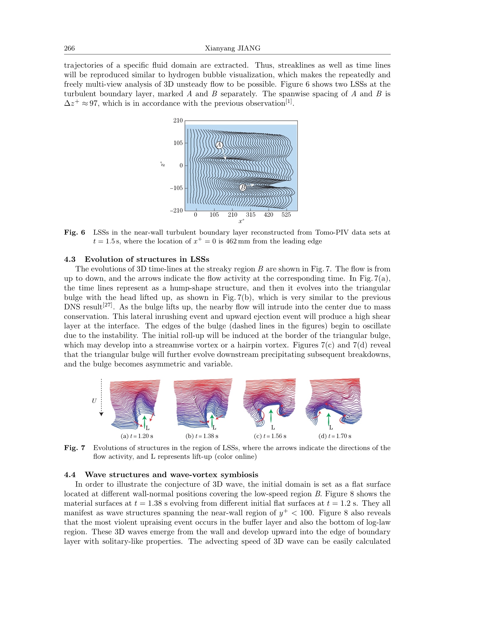
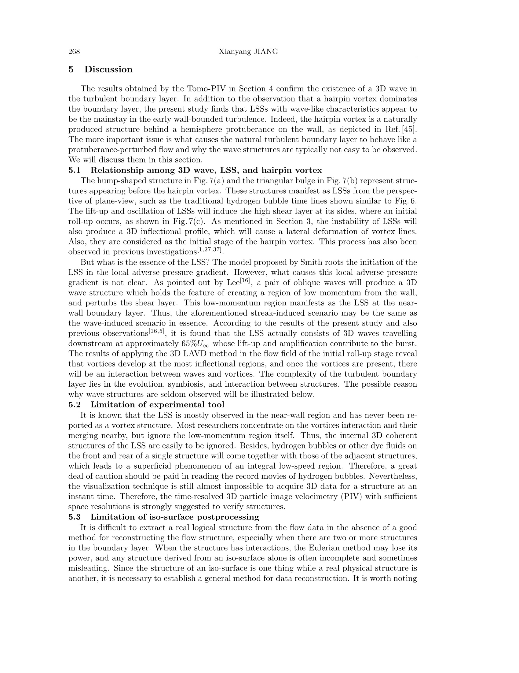
ResearchGateSee discussions, stats, and author profiles for this publication at: https://www.researchgate.net/publication/330803545 Appl. Math. Mech. -Engl. Ed., 40(2), 261-272(2019)Applied Mathematics and Mechanics (English Edition) Revisiting coherent structures in low-speed turbulent boundary layers Article in Applied Mathematics and Mechanics· February 2019 DOI: 10.1007/s10483-019-2445-8 CITATIONS READS3 176 1 author: Jiang X.Y. Peking University 4 PUBLICATIONS 4 CITATIONS SEE PROFILE https://doi.org/10.1007/s10483-019-2445-8 Revisiting coherent structures in low-speed turbulentboundary layers* Xianyang JIANG1,2,T 1. State Key Laboratory for Turbulence and Complex Systems,Peking University, Beijing 100871, China; 2. Department of Aeronautics and Astronautics, College of Engineering, Peking University, Beijing 100871, China (Received Sept.5,2018/Revised Nov. 6, 2018) Abstract Coherent structures are essential for the momentum exchange and turbu-lence production in wall-bounded turbulent flows. Diversified coherent structures havebeen observed in turbulent boundary layers, and hairpin-based vortices dominate mostof the relevant literature. However, there is no consensus yet on the origin and formingmechanism of hairpin vortices.. HIerein, five cornerstones pertaining to the frameworkof hairpin-based coherent structures are reviewed, and three different hairpin generationmechanisms are clarified. Next, the time-resolved tomographic particle inage velocime-try (Tomo-PIV) is used in an early turbulent boundary layer (Reg= 420) to investigatethe origin of hairpin vortices. The timelines reveal a triangular bulge in the low-speedstreak (LSS), and the initial roll-up occurs at two sides of it. Meanwhile, the materialsurfaces manifest as a three-dimensional (3D) wave structure in the LSS, which may sup-port the model of a soliton-like coherent structure (SCS). Subsequently, the method ofLagrangian-averaged vorticity deviation is used to detect early vortices. We find that the3D wave structure is flanked by two vortices, thus confirming the roll-up of timelines anddemonstrating the advantage of the Lagrangian criteria in capturing structures in com-plex flows. These results suggest that various coherent structures may evolve from themetamorphosis of 3D wave structures and their later interaction. Finally, the limitationsof traditional experimental and post-processing tools are discussed. Key words coherent structure, hairpin vortex, soliton-like coherent structure (SCS)Chinese Library Classification0357.5 2010 Mathematics Subject Classification 76F40, 76D17,76D33 Introduction Coherent structures are important in turbulent production, and are regarded as “beasts inturbulent jungle”1]. Over the past half a century, numerous efforts have been devoted in captur- * Citation: JIANG, X. Y. Revisiting coherent structures in low-speed turbulent boundary layers.Applied Mathematics and Mechanics (English Edition), 40(2),261-272 (2019) https://doi.org/10.1007/s10483-019-2445-8 t Corresponding author, E-mail: xyjmh@pku.edu.cn Project supported by the National Natural Science Foundation of China (Nos. 10921202, 11221061,11632002,11521091,11602005, and 91752000) ( @Shanghai U n i v ersity a n d S p ringer-Verlag GmbH Ger m any, part of Springer Nature 2019 ) ing and examining them in both incompressiblel2-9] and compressible[10-14] wall-bounded flows.These structures manifest in a wide variety of shapes and sizes. However, no consistent con-clusion has been presented on the elemental structure. In a low-speed boundary layer, typicalcoherent structures include single structures such as A-vortexl15], soliton-like coherent structure(SCS)[16], horseshoe or hairpin vortexl17], pocket[18], typical eddy[19], and streamwise vortex.Further, there are composite structures such as hairpin packets[20], low-speed streaks (LSSs)[21],chain of ring-like vortices[22], turbulent spots[23],and very large scale motions (VLSM)[24]. Withthe development in numerical simulations and experimental techniques over the last decades,the previously found coherent structures were confirmed and extended, especially by direct nu-merical simulation (DNS)[25-27] and tomographic particle image velocimetry(Tomo-PIV)[28-34S)me these structures are hairpin-like vortices, while others are non-hairpin-like structuresincluding non-vortical wave packets. However, hairpin-like structures (including their asym-metric and composite variations) appear to be the dominant mainstay or the basic element inmost of the literature, although diversified opinions exist from their shapes to their origins.This prevailing hairpin-based concept is sometimes applied crudely, which causes confusion andmisconception of wall-bounded turbulent flows. In this paper, we attempt to clarify the conceptof hairpin-based structure from its original idea to its forming mechanism. The new results fromTomo-PIV are presented to illustrate the characteristic of a three-dimensional (3D) wave, andthe evolution and symbiosis of the wave-vortex are reported. 2 Framework of hairpin-based structures The hairpin-based framework includes all hairpin-like coherent structures regardless ofwhether they are symmetric or asymmetric, such as horseshoes, hairpins, cane-shape structures,arch vortices, and also their composite variations, such as hairpin packets or group hairpins. Itappears that the cornerstones of hairpin-based frameworks are built from following fundamentalhypotheses and classical experiments. 2. 1 Initial hypothesis of horseshoe vortices proposed by Theodorsen Theodorsen (1952)[35] proposed a hairpin vortex model for turbulence production and dis-sipation in wall-bounded flows. In his hypothesis, a two-dimensional (2D) vortex line in theboundary layer moves away from the wall because of an environmental disturbance. Becausethe velocity away from the wall is higher than that near the wall, the middle part of the vor-tex line is stretched into a A-shape structure that grows outward from the wall with headsinclined downstream at 45°, with spanwise dimensions proportional to the distance from thewall, as shown in Fig. 1(a). This model was first identified by Head and Bandyopadhyayl17] ata reasonably high Reynolds number, although the A-vortex was visualized earlier by Hama andNutant[15]. Most observed vortices in the turbulent boundary layer are asymmetric, and arepredominantly distorted as arch-shaped structures, one-legged hairpins, or cane-like structures,as shown in Fig.1(b). They are often observed above the buffer layer, and are considered asthe result of instability of LSSI36-37. (a) Horseshoe vortex model in Ref. [35] (b) Hairpin vortex model in Ref. [3] Fig. 1 Models of horseshoe vortex and hairpin vortex 2.2 Pioneering experimental work of Stanford’s group The first systematic investigation of coherent structures in a turbulent boundary layer datesback to the pioneering work of Stanford’s group[21,38-401. The prime tool in these experimentswas a hydrogen bubble generating wire, mounted normal to the plate. They found that theturbulent bursts, which occurred frequently in the LSS, mainly consisted of ejection eventswith low-momentum fluids rising from the wall and swept down events with high-momentumfluids accelerating downward from the outer layer. This ejection-sweep process and the streakformation and breakup were explained by a mechanism based on vortex stretching and lift-up.The stretched and lifted vortices appear as nascent hairpin vortices. The near-wall burstingprocess was observed to be consistent with the passage of a horseshoe vortex by Offen andKline[40]. The early work of Stanford’s group confirmed that coherent motions were criticalin turbulent production in the near-wall region, and laid the foundation for the research oncoherent structures. 2.3 Original attached-eddy hypothesis of Townsend It is noteworthy that the hypothesis termed as the attached eddy in the monograph ofTownsend (1976)[41] has inspired many researchers in understanding the physical insight ofwall-bounded turbulence, and had guided some classical models[20,42-43. The essence of theattached eddy is that its size is proportional to its distance from the wall. Townsend suggested amodel in the form of conical eddies, and reported that other possibilities exist. This hypothesismay beone of the most important theoretical supports for hairpin models. As stated in Ref. [42],the A-vortex is a perfect candidate for Townsend's attached-eddy hypothesis. 2.4 Synthetic model from kernel studies by Smith and his co-authors The approach of kernel studies was applied in a turbulent boundary layer to examine thevortex dynamics of isolated flow structures1-2,44-47. Therein, hairpin vortices were generatedartificially by a hemisphere protuberance or fluid ejection on the wall, and strong similaritywas found with flow structures detected in bounded turbulent flows. Based on extensive andmanifold experimental works, Smith and his co-authors suggested a model to elucidate thecharacteristics of LSS and the bursting behavior, which are closely associated with the evolutionand regenerative process of hairpin vortices, as shown in Fig. 2. Fig.2 The conceptual model of hairpin vortices duringa bursting process 2.5 Packets and other composite hairpin structures Ad al.[20]pn et al.oprrooppoosseed that different sizes of vortex packets coexist in the boundarylayer, and they are typically layered on the top of each other, as shown in Fig. 3. Small vortexpackages fall in the low-momentum region induced by a large vortex. Large eddy packets arealso wrapped by larger vortex packets in the low-momentum region. A uniform momentumzone is induced by sets of vortices that are longer than those in the low-speed region inducedby a single hairpin vortex. Further, different vortices coexist in a vortex packet, and theirvelocities differ. The packets of hairpin vortices also constitute large-scale motions and VLSMin turbulent flows. Fig. 3 The conceptual scenario of hairpin packet attached to the wall43] (color online) 3 Generation and regeneration of hairpin vortices Models centered around a hairpin vortex are supported by a number of simulations andexperiments. Owing to space limitation, they are not listed herein individually. However, themechanisms of generation and regeneration of a hairpin vortex are still not in consensus. Theyare primarily classified into the following three scenarios. 3.1 Streak instability It is suggested that the origin and the generation of hairpin vortices are caused by the dis-tortion and destabilization of low-speed fluids diffusing from the walll1,36,39,48. Smith proposeda model in 1984 to illustrate that the bursting process of an LSS involved vortex roll-up in theunstable shear layer formed on the top and sides of the streak l. The lift-up and oscillationof the LSS were explained by an impressed local adverse pressure gradient, thus resulting in alocal deceleration and a 3D inflectional profile. Once the inflectional profile develops,the streakwill oscillate owing to local instability. Inner-outer interaction is another mechanism suggested to explain the streak formation andits instabilityl37,49]. The streak instability was also emphasized by Waleffel50] in the model of aself-sustaining process (SSP), which was driven by the instability of streaks instead of rolls. 3.2 Vortex stretching and viscous-inviscid interaction As mentioned in Section 2, Stanford’s investigation interpreted streak formation and breakupbased on vortex stretching and compression inspired by Lighthill’s theoryl51]. Vortices wereconsidered to originate from the stretching-caused intermittency and three-dimensionality ofturbulencel21], which was also supported by Ref.[47]. Further, they indicated that the lateraldeformation of the vortex lines constituted the initial hairpin vortex whose head was observedto form at the interface between an ejected fluid and the inrushing outer flow in the stronginflectional region. Regeneration of hairpin vortices was further proposed as the result of thecombined effect from a local surface pressure gradient induced by a parent hairpin vortex andan inner-outer interaction by the viscous-inviscid mechanism[2,20,52] 3.3 Hairpin vortex developed from 3D wave packet As first depicted by Hama et al.53], to describe fully-developed turbulence as a system ofhorseshoe vortices seems to be straining a concept which is the most valuable in the initialstages. They found that, before the appearance of vortex, there was a special structure calledkink. Therefore, they thought that kink transferred to vortex[15. This kink structure was lateridentified as the SCS by Leel16], and the LSSs as well as bursting process were deemed as the con-sequence of SCS’s behavior 16,5,54-60], as shown in Fig. 4. The hydrogen bubble visualizationresult in Fig. 4(a) shows that the SCS is formed prior to the hairpin vortex. Figure 4(b) indicates the model of SCS and its relevant vortices. When the SCS advects downstream at a speed of0.6U。o~0.8U。, an instability along the border occurs which then leads to a high shear layer.With the fluid inside the SCS moving upward, its surrounding flow will displace downward tocause the initial roll-up (the closed secondary vortex (SV)) which will further develop into thehairpin vortex (see the first ring vortex (FRV) in Fig. 4(b)). Chernyshenko and Baig 61 alsoclaimed that the LSS might not be the result of hairpin vortices. Thus, there is a possibilitythat active 3D wave structures live inside and constitute the LSS. Fig. 4 The hairpin vortex model developed from the SCs 5 (color online) 4 Coherent structures reconstructed from Tomo-PIV data sets 4.1 Experiment setup An experiment is conducted to study the evolution of the coherent structures using Tomo-PIV in an incompressible boundary layer over a flat plate. The experiment was conducted inthe water tunnel at Peking University. The flat plate used is the same as Ref. [60]. Four CMOScameras (1024 pixels×1024 pixels) were used in the time-resolved Tomo-PIV, and they werearranged in a cross configuration, as shown in Fig.5. A laser generator of Beijing ZK Laser Co.,Ltd. (DCQ-30Q) was synchronized with cameras by highspeed controller of LaVision. The sam-pling frequency was set to 500 Hz, and the particle concentration was 2.3 particles/mm. Thefinal residual calibration errors for all cameras were below 0.1 pixels, which were further reducedby using volume self-calibration[62] (to become below 0.01 pixels). The volume reconstructionwas realized by applying the sequential motion tracking enhancement (SMTE) algorithm 63]A multi-pass approach with four steps was implemented in the volume correlation. Finally, thefirst four modes of proper orthogonal decomposition (POD)[64] were extracted to analyze thevelocity field. Fig. 5 Experimental setup of Tomo-PIV, where four CMOS cameras (1 024 pixels×1 024 pixels) wereused to measure the velocity in an area of 78 mmx78mm 4.2 “Visualization”of LSS A 3D velocity field data set was obtained by applying Tomo-PIV in a turbulent boundarylayer at the low Reynolds number (Reg=420). By using a Lagrangian tracking method, the trajectories of a specific fluid domain are extracted. Thus, streaklines as well as time lineswill be reproduced similar to hydrogen bubble visualization, which makes the repeatedly andfreely multi-view analysis of 3D unsteady flow to be possible. Figure 6 shows two LSSs at theturbulent boundary layer, marked A and B separately. The spanwise spacing of A and B is△z+97, which is in accordance with the previous observation 1. Fig. 6 LSSs in the near-wall turbulent boundary layer reconstructed from Tomo-PIV data sets att=1.5s, where the location ofc+= 0 is 462 mm from the leading edge 4.3 Evolution of structures in LSSs The evolutions of 3D time-lines at the streaky region B are shown in Fig. 7. The flow is fromup to down, and the arrows indicate the flow activity at the corresponding time. In Fig. 7(a),the time lines represent as a hump-shape structure, and then it evolves into the triangularbulge with the head lifted up, as shown in Fig.7(b), which is very similar to the previousDNS resultl27. As the bulge lifts up, the nearby flow will intrude into the center due to massconservation. This lateral inrushing event and upward ejection event will produce a high shearlayer at the interface. The edges of the bulge (dashed lines in the figures) begin to oscillatedue to the instability. The initial roll-up will be induced at the border of the triangular bulge,which may develop into a streamwise vortex or a hairpin vortex. Figures 7(c) and 7(d) revealthat the triangular bulge will further evolve downstream precipitating subsequent breakdowns,and the bulge becomes asymmetric and variable. U Fig. 7 Evolutions of structures in the region of LSSs, where the arrows indicate the directions of theflow activity, and L represents lift-up (color online) 4.4 Wave structures and wave-vortex symbiosis In order to illustrate the conjecture of 3D wave, the initial domain is set as a flat surfacelocated at different wall-normal positions covering the low-speed region B. Figure 8 shows thematerial surfaces at t= 1.38 s evolving from different initial flat surfaces at t=1.2 s. They allmanifest as wave structures spanning the near-wall region of y+<100. Figure 8 also revealsthat the most violent upraising event occurs in the buffer layer and also the bottom of log-lawregion. These 3D waves emerge from the wall and develop upward into the edge of boundarylayer with solitary-like properties. The advecting speed of 3D wave can be easily calculated from the positions of wave peak at each time instant. The average streamwise advecting speedof 3D wave is found to be approximately 65% of the freestream velocity. The width W+ofthe wave form is nearly 80, the height H+of the wave form is nearly 80, and the streamwisespan L+is close to 200. The dimension of wave structure is very close to that of the hairpinstructure measured by Smith (see Fig.2). The early work of Smithll] had noticed that theinflected region usually consists of several waves, and the number is generally from 2 to 5.However, these wave structures are usually ignored by most of researchers who focus mainly onthe vortices. According to the works 16,5,54-60] these 3D wave structures may be identified asthe SCS, which was argued to develop from a pair of oblique waves. It is known that there is no universal definition about vortices, and most of identificationschemes on the turbulent boundary layer are based on the instantaneous velocity field 65-66]We try to further examine the flow by applying the Lagrangian detecting method. An objec-tive vortices criterion called the Lagrangian-averaged vorticity deviation (LAVD) was proposedrecentlyl67], which is implemented to detect vortex boundaries in the present study. The LAVDis defined as67 where Xo is the initial material domain, w is the vorticity, and w is the averaged local vorticityover the domain ofX(t; Xo). The structures detected by the tubular level surfaces of the LAVDare the Lagrangian coherent structures, which are the objectives to the coordinate frame. Fora more thorough description about this method, see Refs. [67] and [68]. Figure 9 shows two quasi-streamwise vortices Vi and V by the LAVD method at t=1.56 s.They are located at two sides of a wave structure, which is a material surface evolving fromthe flat surface initiated at y+=27,and t=1.2 s. It is illustrated that the vortices emerge atthe most inflectional region of the material surface, and they are not symmetrically distributed.Since no vvoortical structure is detected by the traditional Eulerian method in this study, we mayconclude that the Lagrangian method has advantages in detecting the early vortex in the highshear layer. This is because most Lagrangian methods inspect and trace a domain of fluids fora finite time, which is easier to extract key structures with few effects from instantaneous noise.It is hard to read the cause and effect of wave-vortices only from Fig.9. Most observations inthe turbulent boundary layer find the symbiosis of wave structures, vortices, LSSs, and alsoother composite structures, and there must be the mutual induction among them. However,the saturate vortices are the most obvious structures to attract attention. Fig. 8 Material surfaces evolving from dif-ferent initial height levels (color on-line) Fig.9 Symbiosis of wave structures and La-grangian vortices Vi and V (color on-line) 5 Discussion The results obtained by the Tomo-PIV in Section 4 confirm the existence of a 3D wave inthe turbulent boundary layer. In addition to the observation that a hairpin vortex dominatesthe boundary layer,the present study finds that LSSs with wave-like characteristics appear tobe the mainstay in the early wall-bounded turbulence. Indeed, the hairpin vortex is a naturallyproduced structure behind a hemisphere protuberance on the wall, as depicted in Ref. 45].The more important issue is what causes the natural turbulent boundary layer to behave like aprotuberance-perturbed flow and why the wave structures are typically not easy to be observed.We will discuss them in this section. 5.1 Relationship among 3D wave, LsS, and hairpin vortex The hump-shaped structure in Fig.7(a) and the triangular bulge in Fig.7(b) represent struc-tures appearing before the hairpin vortex. These structures manifest as LSSs from the perspec-tive of plane-view, such as the traditional hydrogen bubble time lines shown similar to Fig.6.The lift-up and oscillation of LSSs will induce the high shear layer at its sides, where an initialroll-up occurs, as shown in Fig.7(c). As mentioned in Section 3, the instability of LSSs willalso produce a 3D inflectional profile, which will cause a lateral deformation of vortex lines.Also, they are considered as the initial stage of the hairpin vortex. This proce.1.27.37ss has also beenobserved in previous investigations1,27,37. But what is the essence of the LSS? The model proposed by Smith roots the initiation of theLSS in the local adverse pressure gradient. However, what causes this local adverse pressuregradient is not clear. As pointed out by Leel16], a pair of oblique waves will produce a 3Dwave structure which holds the feature of creating a region of low momentum from the wall,and perturbs the shear layer. This low-momentum region manifests as the LSS at the near-wall boundary layer. Thus, the aforementioned streak-induced scenario may be the same asthe wave-induced scenario in essence. According to the results of the present study and alsoprevious observationsl16,5], it is found that the LSS actually consists of 3D waves travellingdownstream at approximately 65%U。。 whose lift-up and amplification contribute to the burst.The results of applying the 3D LAVD method in the flow field of the initial roll-up stage revealthat vortices develop at the most inflectional regions, and once the vortices are present, therewill be an interaction between waves and vortices. The complexity of the turbulent boundarylayer lies in the evolution, symbiosis, and interaction between structures. The possible reasonwhy wave structures are seldom observed will be illustrated below. 5.2 Limitation of experimental tool It is known that the LSS is mostly observed in the near-wall region and has never been re-ported as a vortex structure. Most researchers concentrate on the vortices interaction and theirmerging nearby, but ignore the low-momentum region itself. Thus, the internal 3D coherentstructures of the LSS are easily to be ignored. Besides, hydrogen bubbles or other dye fluids onthe front and rear of a single structure will come together with those of the adjacent structures,which leads to a superficial phenomenon of an integral low-speed region. Therefore, a greatdeal of caution should be paid in reading the record movies of hydrogen bubbles. Nevertheless,the visualization technique is still almost impossible to acquire 3D data for a structure at aninstant time. Therefore, the time-resolved 3D particle image velocimetry (PIV) with sufficientspace resolutions is strongly suggested to verify structures. 5.3 Limitation of iso-surface postprocessing It is difficult to extract a real logical structure from the flow data in the absence of a goodmethod for reconstructing the flow structure, especially when there are two or more structuresin the boundary layer. When the structure has interactions, the Eulerian method may lose itspower, and any structure derived from an iso-surface alone is often incomplete and sometimesmisleading. Since the structure of an iso-surface is one thing while a real physical structure isanother, it is necessary to establish a general method for data reconstruction. It is worth noting that most people concentrate their postprocessing on finding the structure with high vorticity.However, not all the coherent structures are vortices. In the wave structure, for example, thereis little vorticity. 5.4 Eulerian view and Lagrangian view There are various definitions and detection methods of vortices, and most of them are frame-dependant based on the localized Eulerian criteria, from which reading the cause and effect israther difficult...In contrast, the Lagrangian tracing method has shown its effectiveness incapturing structures in complex flows with the DNS[26-27,69-72. Though, precisely extractinga structure in the experiments is just a beginning in the turbulent boundary layer. It needstime-resolved experimental techniques that have enough space resolution with low noise. Theadvantage of Lagrangian criteria is that extracting the evolution and interaction of structures ispossible, which is usually absent in the previous investigation by applying the Eulerian method.Since the Eulerian method holds its superiority in instantaneous velocity fields especially wherethe viscous effect cannot be ignored, the combination of Lagrangian-based criteria with thosetraditional Eulerian methods is a potential path to obtain a complete structure as well as theirevolution. Overall, it must be admitted that the fact-based framework of hairpin-based structures isuseful in understanding turbulent boundary layers. The present work just provides anotherperspective to view the early turbulent flow on a flat plate. Since the 3D wave structures couldbe traced back to early transitional boundary layers, the generation of various coherent struc-tures may be considered as the results of metamorphosis and evolution of 3D wave structuresand their later symbiosis and interaction. 6 Conclusions Many viewpoints about the hairpin vortex cannot be united due to the diversified observa-tion in experiments and simulations. The hairpin-based framework is indeed one of the gooddepictions in wall-bounded turbulent flows, though the origin of hairpins vortex is in lack ofphysical and clear explanation. This paper tries to clarify the history and different explanationsof the framework, and discusses the limitations in experimental techniques and postprocessingmethods. Besides, new results based on the time-resolved Tomo-PIV are presented. The evo-lution of different coherent structures is extracted from the 3D velocity data sets by applyingthe Lagrangian tracking method. It is found that the LSS manifests as a 3D wave structure.The hump-shaped structure located in the streaky region will evolve into the triangular bulgewhose edges oscillate violently due to the instability caused by fluid activity of lateral inrushand upward ejection. 3D wave structures reconstructed from the evolution of material surfacesseem to support the SCS theory 16,5]. The dimensions of the 3D wave are W+~80, H+~80,and L+~ 200. The propagation speed of the wave is approximately 65% of the freestreamvelocity. By using the LAVD vortices detecting method, quasi-streamwise vortices are foundat the sides of the 3D wave. According to the observation of the author and also the previousstudy, it is concluded that the 3D wave structure is the initiator of hairpin vortices. Due to theadvantage in identifying coherent structures, the Lagrangian method seems to be a promisingtool in resolving a large number of data derived from the DNS and Tomo-PIV. References [1] SMITH, C. R. A synthesized model of the near-wall behavior in turbulent boundary layers. Pro-ceedings of the 8th Symposium of Turbulence (eds. PATTERSONAND,G. K. and ZAKIN, J. L.),University of Missouri-Rolla, Rolla (1984) SMITH, C. R., WALKER, J. D. A., HAIDARI, A. H., and SOBRUN, U.On the dynamics ofnear-wall turbulence. Philosophical Transactions: Physical and Engineering Sciences, 336, 131-175 (1991) ( 3] R OBINSON, S. K. C oherent moti o ns in the t urb u lent boun d ary layer . Annu a l Revie w of Fluid Mechanics, 23, 601-639 (1991) ) ( [4] LEE, C . B. a nd CHEN,S. Y . Dyn a mics of b o undary layer tran s ition. Tra n sition and Tur b ulentControl, 2, 39-86 ( 2006) ) ( 5] 1 L EE, C. B. and W U , J. Z. Tr a nsition in w a ll-bounded flows. Applied Mechanics Reviews, 6 1 ,030802 (2008) ) ( 6] Z HONG, H., CHEN, S., an d L EE, C. B . Experimental study of freely falling thin disks: tr a nsitionfrom planar zigzag t o s piral. Physics of Fluids , 23 , 011702 (2011) ) ( [7 ] L EE, C. B., SU, Z., ZHONG,H., CHEN, S. , Z H OU, M., and WU, J. Experimental in v estigationof f reely falling thin disks, part 2: transition o f three-dimensional motion fro m zigzag to spiral.Journal of Fluid M echanics, 7 32, 77-1 0 4 (2013) ) ( 8 Z HU, Y., C HEN, X . , WU, J., CHEN, S. , L E E, C. B., and GAD-EL-HAK, M. A er o dynamicheating i n t ransitional hypersonic b oundary layers: role o f second-mode instability. Physics ofFluids, 30,011701 (2018) ) ( 9] J IMENEZ, J. Coherent structures in wall-bounded tu r bulence. Journal of Fluid Mechanics, 842,513-531 (2018) ) ( [10 ] Z HU,Y. D., YUAN,H. J., ZHANG, C. H., and LEE, C. B. Image-preprocessing method for near-wall particle image velocimetry (PIV) image in t errogation wi t h very large in-plane displacement.Measurement Science a n d Technology, 2 4 , 1 2 5302 ( 2 013) ) ( [11] ZHANG, C. H . , T A NG,Q., and LEE, C. B. Hypersonic bound a ry-layer transition on a flar e dcone. Acta Mechanica Sinica, 29,48-54 (2013) ) ( [12 ] Z HU, Y. , Z HANG, C. H., C H EN, X., Y U AN, H., WU, J., CHEN, S. Y., LEE , C. B., and GAD-EL-HAK,M. Tra n sition in hy p ersonic bo u ndary layers: role of dilatational waves. AIAA J ournal,54,3039-3049 ( 2016) ) ( [13 CHEN, X.,ZHU, Y., and LEE, C. B. Interactions between second mode and low-frequency wavesin a hypersonic boundary l a yer. J ournal of Fluid Mechanics, 8 2 0, 6 9 3-735 (2 0 17) ) ( [14 L EE, C. B. and CHEN, S. Y. A review of recent progr e ss in th e study of transition in hypersonicboundary l a yer. N ational Science R e view, n w y052 (2 0 18) ) ( [15] :H AMA, F. R. an d NUTANT , J. Detai l ed flow-field obs e rvations in th e transition process in athick boundary l a yer. Proceedings of the H e at Transfer an d Fluid Mechanics Institute, 16, 77-93(1963) ) ( [16 ] L EE, C. B. Ne w fea t ures of CS solitons and the formation of v o rtices. Phy s ics Letters A, 2 47 , 397- 4 02(1998) ) ( [17 ] HEAD,M. R. and BANDYOPADHYAY, P. New aspects of turbulent boundary-layer structure.Journal of Fluid M echanics, 107, 2 9 7-338 (1981) ) ( [18 ] F ALCO, R. E. The rol e of outer flow coherent m o tions in the production of turbulence near a wall.Proceedings ofAFOSR Wo r kshop on C oh e rent Structure of Turbulent Boundary Layers, LehighUniversity, Bethlehem, PA (1978) ) ( [19] CHU, C. and F A LCO, R. E . Vor t ex rin g /viscous wall layer interaction model of the t u rbulenceproducti o n process n e ar walls. Experiments in Fl u ids, 6, 305-31 5 (198 8 ) ) ( [20 ] ADRIAN,R. J . , M EINHART, C. D., an d TO M KINS, C. D . Vort e x organization in the outerregion of the turbulent boundary layer. Journal of Fluid Mechanics, 422, 1-54 (2000) ) ( [21] KLINE, S.J . , REYNOLDS, W. C., SCHRAUB, F. A. , and RUNSTADLER, P. W. The structureof turbulent boundary l ayers. Journal of Fluid Mechanics, 30, 741C773 (1967) ) ( [22K A CHANOV, Y. S. Physical mechanisms of laminar-boundary-layer transition. Annual Re v iew of Fluid Mechanics, 26, 411-482 ( 1 994) ) ( [23 ] E MMO N S, H. W. T h e lamin a r-turbulent trans i tion in a bo u n d ary layer , part I. J o u r nal oftheAeronautical Sciences, 18, 490-498 (1951) ) ( 24] K IM, K . C. a n d ADRIAN, R. J. Ver y large-scale motion in the outer layer. Physics of Fluids, 11, 4 17-422 (1999) ) ( [25] WU, X . a n d MOIN, P. Direct numerical simu l ation of turb u lence in a no m inally zero- p ressure-gradient f lat-plate boundary layer. J ournal o f Fluid Mechanics, 630, 5C41 (2009) ) ( [26] CHEN,W. Numerical Simulation of B oundary Layer Transition by C om b ined Comp a ct DifferenceMethod, Ph. D. d issertation, Nanyang Technological University, Singapore (2013) ) ( [27 ]Z HAO, Y., YANG, Y., and CHEN, S. Evol u tion of material surfaces in the temporal transitionin channel flow. Journal of Fluid Mechanics, 793,840-876 (2016) ) ( [28 ] SCHRODER, A., GEISLER, R., ELSINGA, G. E. , SCARANO, F., and DIERKSHEIDE, U. Investigation of a turbulent spot and a t ripped turbulent b o undary layer flow using time-resolvedtomographic PIV. E x periments in Fluids, 44,3 0 5-316 (2008) ) ( [29 DENNIS, D . J . C. a n d N I CKELS, T. B. Exp e rimental me a surement of l arge-scale three-dimensional s tructures i n a t urbulent b oundary la y er, p a rt 1 : vortex packets. Journal of FluidMechanics, 673, 180-217 (2011) ) ( [30] A . TKINSON, C., COUDERT, S. , F O UCAUT, J. M. , S T ANISLAS, M., a nd S O RIA, J. Tomo-graphic part i cle image velocimetry measurements o f a high Reynolds n u mber tu r bulent bo u nd-ary l ayer. Progress in V Wall Turbulence: Understanding and Modeling (eds. STANISLA S , M . ,JIMENEZ, J. , a n d M A RUSIC,I.), S pringer Netherlands, Dordrecht, 113-120 ( 201 1 ) ) ( [31] TANG, Z . Q., JIANG, N., SCHRODER, A., and GEISLER,R. T omographic PIV investigation of coherent structures in a turbulent boundary layer flow. Acta Mechanica Sinica, 28, 572-582 (2012) ) ( 32 ] G AO, Q., ORTIZ-DUENAS,C., and L ONGMIRE, E. Evolution of coh e rent structures in turbu-lent boundary layers b ased on m oving tomographic PIV. Esp e riments in F l ui d s, 54, 162 5 (2013) ) ( [33] S : ABATINO,D. R. and ROSSMANN,T. Tomog r aphic PIV measurements of a regenerating hair-pin vortex. Experiments in Fluids, 57,6(2 0 16) ) ( 34]. J ODAI,Y. an d EL S INGA, G. E. E x perimental observation of hairpin auto-generation events ina turbulent boundary layer. J ournal of F luid Mechanics, 795, 611- 6 33 (2016) ) ( [35 ]T HEODORSEN, T. Mech a nism of turbulence. Proceedings of Second Midwestern Conference onFluid Mechanics, Ohio S t ate U n iversity, C olumbus (1 9 5 2) ) ( [36 ] S CHOPPA, W. and HUSS A IN, F. Coherent structure generation in near-wall turbulence. JournalofFluid Mechanics, 453, 57C108 (2002) ) ( [37 ] S TANISLAS,M. Near wall turb u lence: an experimental view. Phys i cal Review Fluids, 2, 100 5 06 (2017) ) ( [38 ]R UNSTADLER, P. W., KLINE,S. J.,and REYNOLDS, W. C. An Experimental Investigation ofthe Flow Structure of the Turbulent B o undary Lay e r, Sta n ford Univ e rsity, California (1963) ) ( [39] KIM, H. T ., KLINE, S. J., and REYNOLDS, W. C. Th e production of turbulence near a smoothwall in a turbulent boundary layer. Journal o f Fluid Mechanics, 5 0, 1 33- 6 0 (1971) ) ( [40] OFFEN, G.R. a nd KLINE, S. J. A proposed model of the bursting process in t u rbulent boundarylayers. Journal of Fluid Mechanics, 70, 209-228(1975) ) ( [41] TOWNSEND, A. A. The Structure of T ur b ulent Shear Flow, 2n d ed., Cambridge University Press,Cambridge (1976) ) ( [42 PERRY, A. E. and CHONG, M. S. O n the mechanism of wall turb u lence. Jou r nal of FluidMechanics, 119, 1 73C217 ( 1 982) ) ( [43] ADRIAN, R . J. H ai rpin vo r tex organization in wall t u rbulence. P h ysics o f F l uids, 19,041301(2007) ) ( [44] SMITH, C. R. and PAXSON, R. D. A tec h nique for evaluation o f three-dimensional behavior inturbulent boundary layers u sing c omputer a u gmented hydrogen bub b le-wire flow vis u alization. Ecperiments in Fluids, 1, 43-49 (1983) ) ( [45] ACARLAR, M. S . a nd SMITH, C. R. A s tu d y of hairpin vorti c es in a la m i n ar boun d ary layer , part 1 : h airpin v ortices generated b y a h e misphere pr o tuberance. Journal of F luid Mechanics,175, 1 C41 ( 1987) ) ( [46 ] ACARLAR,M. S. and SMITH, C. R. A stu d y of hairpin vort i ces in a l aminar boundary layer, part2: hairpin vortices generated b y fluid injection. Journal of Fluid Mechanics, 1 7 5,43 - 8 3 (19 8 7) ) ( [47] HAIDARI, A. H. and SM I TH, C. R. The generation and rege n eration of s i n g le hairpin vortices.Journal o f Fluid M echanics, 277, 1 3 5-162 (1994) ) ( [48] FALCO, R. E. A coherent str u cture model of the turb u lent boundary layer and its ability to predictReynolds n umber d e pendence. Philosophical Transactions: iPhysical S ciences a nd E ngineering, 336, 103- 1 29 (1991) ) ( [49] MARUSIC, I., MATHIS, R. , an d HU T CHINS, N. Pr e di c tive model for wall - bounded turb u lentflow. Science,329,1 9 3-196 ( 2 010) ) ( [50 ] W ALEFFE,F. On a self-sustaining process in shea r flow s . Phy s ics of Fluids, 9, 88 3 -900 (19 9 7) ) ( [51L I GHTHILL,J. Ac o ustic streaming. Jour n al of Sound and Vibra t ion, 61, 3 91-418 ( 1978) ) ( [52] ZHOU, J., ADRIAN, R. J., BALACHANDAR, S., and KENDALL, T. M. Mechanisms for gen-erating coherent p ackets of hairpin v ortices i n channel f low. J ournal of Fluid Mechanics, 387,353-396 (1999) ) ( [53 ]H AMA,F. R., L ONG, J. D. , and HEGARTY,J. C.On transition from laminar to turbulent flow.Journal o f Applied Physics, 28, 388 - 394 (1957) ) ( [54 ]L EE, C. B. Po s sible universal tr a nsitional scenario in a flat p l ate b o undary layer: me a surementand visualization. P hysical R eview E , 6 2 , 3 6 59-36 7 0 (2000) ) ( 55] LEE, C. B., HONG, Z. X.,KACHANOV, Y. S., BORODULIN, V.I., and GAPONENKO, V.V.A s tudy in transitional flat plate boundary layers: measurement an d visualization. Experiments in Fluids, 28, 243 - 251 ( 2000) ) ( [56 L] EE, C. B. and FU, S. On the formation of the chain of ring-like vortices in a transitional boundarylayer. Experiments in Fluids , 30 , 35 4 -357 ( 2001) ) ( 57] L EE,C. B. On the formation of the streamwise vortex in a tr a nsitional boundary layer (in Chi-nese). Acta Physica Sinica, 50, 182- 1 84 ( 2001) ) ( 58 LI, R. Q. and LEE, C. B. A link be t ween chaos dynamics and the onset of t urbulence in atransitional boundary l a yer (in C hinese). Acta Physica Si n ica, 51, 17 4 3-1749 (20 0 2) ) ( [59] LEE, C. B. CS-soliton: i ts feature and importance (in Chinese). Experiments and Measurementsin Fluid Mechanics, 17, 5 7-60 (2003) ) ( [60] LEE,C . B. a n d LI, R . Q. Dominant st r ucture fo r turbulent production in a transitional b oundarylayer. Journal o f T urbulence, 8, 1-34 (2007) ) ( [61] CHERNYSHENKO, S. I . a n d BAIG, M. F. Th e mechanism of str e ak forma t ion in ne a r-wallturbulence. Journal of Fluid Mechanics, 544, 99-131 (2005) ) ( [62] WIENEKE, B. Volume self-calibration for 3 D particle imag e velocimetry. Experiments in Fluids, 45, 549 - 556 ( 2008) ) ( [63 ] L YNCH, K. P. and SCARANO, F. An eff i cient and accurate approach to MTE-MART for time-resolved tomographic P I V. E x periments in Fl u ids, 56, 66(2015) ) ( [64 ]M OIN, P. and MOSER, R. D . Characteristic-eddy decomposition of t u rb u lence in a channel.Journal of Fluid Mechanics, 200, 471-509(1989) ) ( [65] CHONG, M. S., P E RRY, A. E., and CANTWELL, B. J. A gener a l c lassification of th r ee-dimensional flow fields. Physic s of Fluids A : Fluid Dynamics, 2,765-777 ( 1990) ) ( 66 CHAKRABORTY, P., BALACHANDAR,S., and ADR I AN, R. J. On the relationships between l ocal vortex i dentification schemes. J ournal of Fluid Mechanics, 535, 18 9 -214 (20 0 5) ) ( 67] H ALLER,G.,HADJIGHASEM, A., FARAZMAND,M., and HUHN, F. Defining coherent vorticesobjectively from the vorticity. Journal o f Fluid M echanics, 7 9 5, 136-173 (2016) ) ( 68 : H ALLER, G. Dynamic rotation and stretch tensors from a dynamic polar decomposition. Journalof the Mechanics and Physics o f S o lids, 86, 7 0-93 (2016) ) ( [69 ]Y ANG,Y. and PULLIN, D. I. On Lagrangian and vo r tex-surface fields for flows with Taylor-Greenand K ida-Pelz initial conditions. Journal of Fluid Mechanics, 661, 446-481 ( 2010) ) ( [70 ] Y ANG, Y. a n d PUL L IN, D. I. Ev o lution of vortex-surface fields in viscous Ta y lor-Green andKida-Pelz f lows. Journal of Fluid Mechanics, 685, 146 - 164 (2011) ) ( [71 ] Z HAO, Y. , Y ANG, Y., a nd CHEN , S. Vor t ex reconnection in the la t e transition in ch a nnel flow.Journal o f F luid M echanics, 802, R 4 (2016) ) ( [72] ZHAO, Y., X IONG, S . , Y A NG, Y. a nd CHEN, S. Si n uo u s disto r tion of vortex sur f aces in th e lateral growth o f turbulent s pots. P hysical R euiew F l uids, 3,074701 (2 0 18) ) All content following this page was uploaded by Jiang X.Y. on February View publication stats Coherent structures are essential for the momentum exchange and turbulence production in wall-bounded turbulent flows. Diversified coherent structures have been observed in turbulent boundary layers, and hairpin-based vortices dominate most of the relevant literature. However, there is no consensus yet on the origin and forming mechanism of hairpin vortices. Herein, five corner stones pertaining to the framework of hairpin-based coherent structures are reviewed, and three different hairpin generation mechanisms are clarified. Next, the time-resolved tomographic particle image velocimetry (Tomo-PIV) is used in an early turbulent boundary layer (Reθ = 420) to investigate the origin of hairpin vortices. The timelines reveal a triangular bulge in the low-speed streak (LSS), and the initial roll-up occurs at two sides of it. Meanwhile, the material surfaces manifest as a three-dimensional (3D) wave structure in the LSS, which may support the model of a soliton-like coherent structure (SCS). Subsequently, the method of Lagrangian-averaged vorticity deviation is used to detect early vortices. We find that the 3D wave structure is flanked by two vortices, thus confirming the roll-up of timelines and demonstrating the advantage of the Lagrangian criteria in capturing structures in complex flows. These results suggest that various coherent structures may evolve from themetamorphosis of 3D wave structures and their later interaction. Finally, the limitationsof traditional experimental and post-processing tools are discussed
确定


还剩11页未读,是否继续阅读?

产品配置单


北京欧兰科技发展有限公司为您提供《低速湍流边界层中速度场,相干结构检测方案(粒子图像测速)》,该方案主要用于其他中速度场,相干结构检测,参考标准--,《低速湍流边界层中速度场,相干结构检测方案(粒子图像测速)》用到的仪器有体视层析粒子成像测速系统(Tomo-PIV)、LaVision DaVis 智能成像软件平台
推荐专场


相关方案
更多
该厂商其他方案
更多