


方案详情
文
采用结构化平面激光照明成像SLIPI对空心喷雾的平面液滴粒径采用LIF/MIE比值全局粒径测量方法进行了测量和分析。采用SLIPI方法可以有效消除杂散光的影响,使得这种方法特别适合于致密喷雾的粒径测量和分析。
方案详情

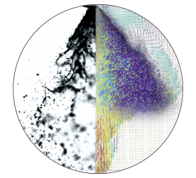
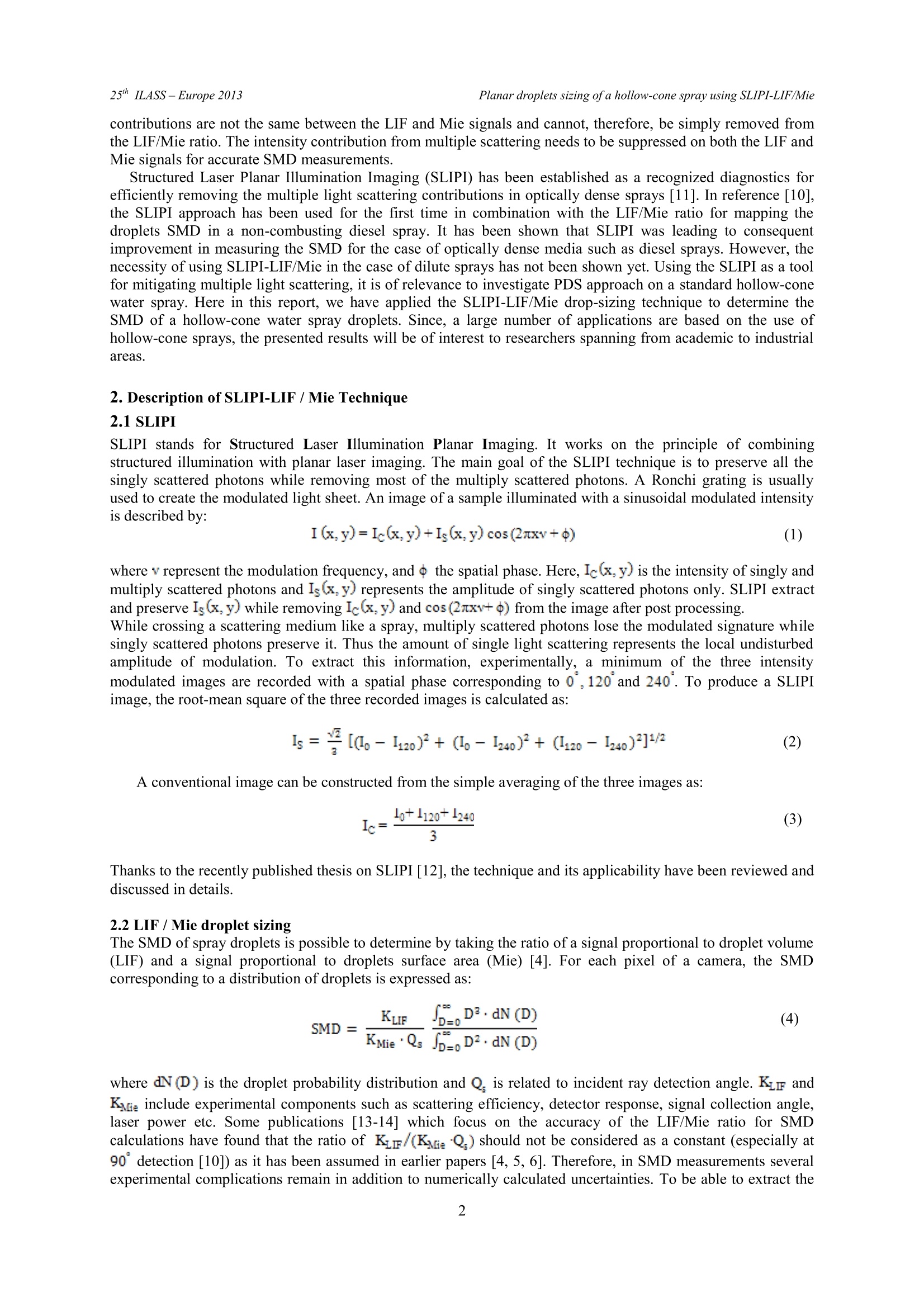
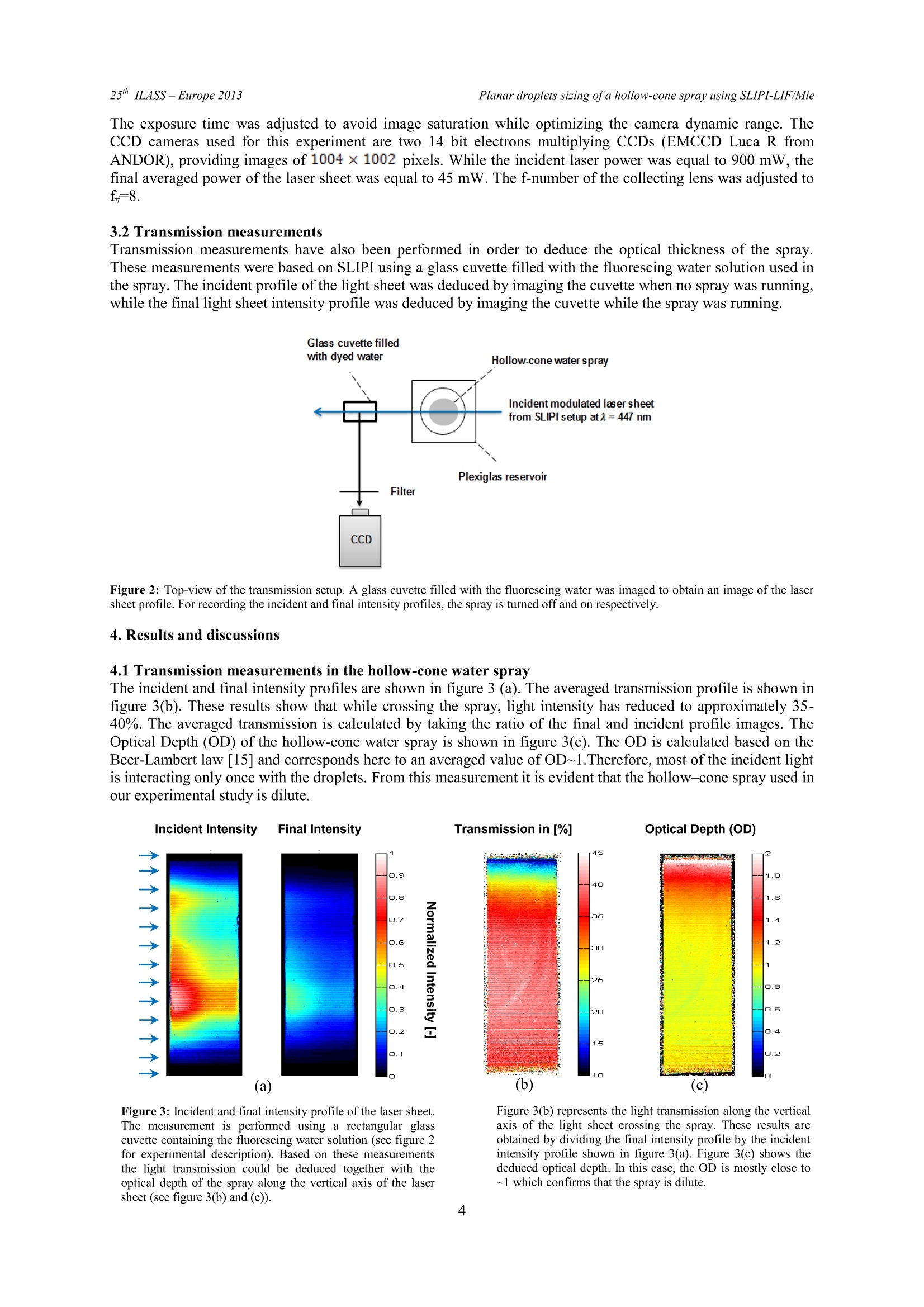
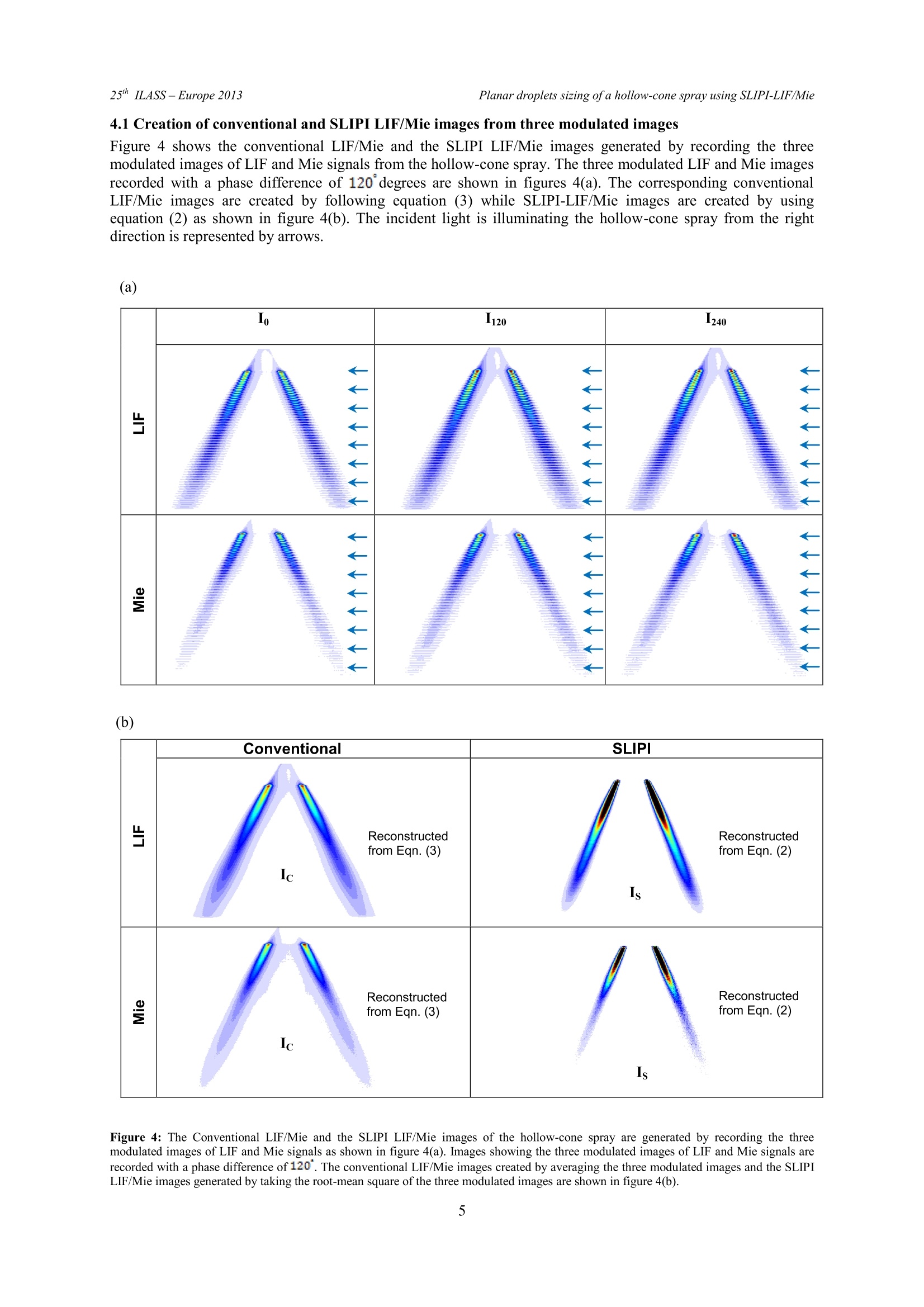
ILASS -Europe 2013, 25" European Conference on Liquid Atomization and Spray Systems, Chania, Greece, 1-4 September 2013 Planar droplets sizing of a hollow-cone spray using SLIPI-LIF/Mie25" ILASS- Europe 2013 Planar droplets sizing of a hollow-cone spray using SLIPI-LIF/MIE Y.N. Mishra. E. Kristensson . S.G. Pettersson and E. Berrocal* Division of Combustion Physics, Lund University, SE-22100, Lund, Sweden Abstract In this work, we report an original experimental approach for measuring the two-dimensional distribution of thedroplets Sauter Mean Diameter (SMD) using the SLIPI-LIF/MIE technique. A hollow-cone spray is formed bycontinuously injecting water mixed with a non-toxic fluorescing dye at 20 bars injection pressure. The spray isilluminated using a continuous wave laser. The illumination wavelength (here, 447 nm) is carefully chosen toexcite the injected dye/water mixture, which generates a significant Laser Induced Fluorescence (LIF) signalpeaking at 514 nm. The LIF and Mie signals are simultaneously recorded using two CCD cameras and theirintensity ratio is used to extract a two-dimensional distribution of the droplets SMD. In this article, we show thaeven for the case of a dilute hollow-cone spray, where single scattering events are in majority, the LIF/Miemeasurement of droplets SMD still remains strongly affected by multiple light scattering. We demonstrate, then,that the use of SLIPI is unavoidable to obtain trustable SMD measurements based on the LIF/Mie ratio, even foroptically dilute sprays. 1. Introduction The practical demands of high performance of liquid atomizer based combustion devices have necessitatedimproving the atomization process since it is directly linked to the efficiency of the device. The performance of aspray is judged by its ability to disintegrate the bulk liquid into micrometric droplets which transport andevaporate prior to combustion. This characteristic of a spray decides the efficiency as well as features of anyliquid driven combustion system. It is therefore significant to investigate the spray structure with both hightemporal and spatial resolution. Droplets sizing is a key component for determining the spatial distribution ofspray morphology and for quantitative characterization of spray. In the past, various optical measurement techniques have been developed to determine droplet sizedistributions. One of the first optical approaches for drop-sizing was reported in 1976 and is known as ensemblelight scattering [1]. The ensemble light scattering (ELS) is a line-of-sight technique, which detects forwardscattered light from the particles in a light path formed by collimated laser beam. Prior to its arrival at thedetector, the non-scattered signal from the droplets passes through a Fourier Transform lens to generate atdiffraction pattern. For each spherical particle, this diffraction pattern represents a concentric laser light ring.Widely spaced rings represents small spherical particles whereas, a large spherical particle represents closelyspaced rings. Apart from these features, the ELS measurement provides a poor spatial resolution and is verysensitive to multiple light scattering issues. In the early eighties, Phase Doppler anemometry (PDA)[2-3] wasintroduced as a point measurement technique for measuring the spray droplet diameters. Today, the technique isused as a standard tool for simultaneous real time measurement of the geometric size of droplets and velocity.Even though, it is a well-established and accurate tool for droplet characterization, the PDA measurements cantake several hours due to point by point scanning over the wide-spread spray. Also, the technique fails to giveany data in optically dense media. In the year 1993, planar drop-sizing (PDS) was first time implemented in a transient spray as an imaging toolfor instantaneous two-dimensional mapping of the droplets distribution [4]. In PDS, the LIF and Mie signalsfrom a light sheet illuminated media are simultaneously recorded and the intensity ratio of the LIF and Miesignal yields relative SMD of spray droplets [4-+7-]. As an advanced technique, PDS has two main advantagesover PDA, first, /improved spatial resolution and second, the faster measurement over a wider section of a spray.However, discrepancies in PDS measurements remained prominent mainly due to the multiple light scatteringand the SMD measurements were not reliable. Later, polarization ratio method(PRM) was developed formeasuring the relative SMD [8]. In PRM, a 45° polarized laser beam crosses a spray and the vertical andhorizontal components ofMie signal are simultaneously recorded with two cameras. The ratio ofthe vertical andhorizontal components is used to deduce the geometrical mean diameter. PRM technique has not been exploredmuch due to the multiple light scattering issues. Therefore, all the above mentioned techniques are efficientlyapplicable only in low droplets densities to avoid signal perturbations introduced by multiple light scattering. Inoptically dense sprays, measurements are“paralyzed”by both multiple light scattering and light extinction. Adetailed study has been reported in reference [9], on the account for light extinction and multiple scattering inPDS of dense sprays. Recent results [10] from planar droplet sizing have shown that multiple light scattering ( C o rresponding author: edouard.berrocal@forbrf.lth.se ) contributions are not the same between the LIF and Mie signals and cannot, therefore, be simply removed fromthe LIF/Mie ratio. The intensity contribution from multiple scattering needs to be suppressed on both the LIF andMie signals for accurate SMD measurements. Structured Laser Planar Illumination Imaging (SLIPI) has been established as a recognized diagnostics forefficiently removing the multiple light scattering contributions in optically dense sprays [11]. In reference [10],the SLIPI approach has been used for the first time in combination with the LIF/Mie ratio for mapping thedroplets SMD in a non-combusting diesel spray. It has been shown that SLIPI was leading to consequentimprovement in measuring the SMD for the case of optically dense media such as diesel sprays. However, thenecessity of using SLIPI-LIF/Mie in the case of dilute sprays has not been shown yet. Using the SLIPI as a toolfor mitigating multiple light scattering, it is of relevance to investigate PDS approach on a standard hollow-conewater spray. Here in this report, we have applied the SLIPI-LIF/Mie drop-sizing technique to determine theSMD of a hollow-cone water spray droplets. Since, a large number of applications are based on the use ofhollow-cone sprays, the presented results will be of interest to researchers spanning from academic to industrialareaS. 2. Description of SLIPI-LIF /Mie Technique 2.1 SLIPI SLIPI stands for Structured Laser Illumination Planar Imaging. It works on the principle of combiningstructured illumination with planar laser imaging. The main goal of the SLIPI technique is to preserve all thesingly scattered photons while removing most of the multiply scattered photons. A Ronchi grating is usuallyused to create the modulated light sheet. An image of a sample illuminated with a sinusoidal modulated intensityis described by: where v represent the modulation frequency, and 中 the spatial phase. Here,Ic(x,y) is the intensity of singly andmultiply scattered photons and Is(x.y) represents the amplitude of singly scattered photons only. SLIPI extractand preserve Is(x, y) while removing Ic(x,y)and cos(2nxv+) from the image after post processing. While crossing a scattering medium like a spray, multiply scattered photons lose the modulated signature whilesingly scattered photons preserve it. Thus the amount of single light scattering represents the local undisturbedamplitude of modulation. To extract this information, experimentally, a minimum of the three intensitymodulated images are recorded with a spatial phase corresponding to 0 , 120 and 240. To produce a SLIP]image, the root-mean square of the three recorded images is calculated as: A conventional image can be constructed from the simple averaging of the three images as: Thanks to the recently published thesis on SLIPI [12], the technique and its applicability have been reviewed anddiscussed in details. 2.2 LIF/Mie droplet sizing The SMD of spray droplets is possible to determine by taking the ratio of a signal proportional to droplet volume(LIF) and a signal proportional to droplets surface area (Mie) [4]. For each pixel of a camera, the SMDcorresponding to a distribution of droplets is expressed as: where dN (D) is the droplet probability distribution and Q. is related to incident ray detection angle. Kur andKMie include experimental components such as scattering efficiency, detector response, signal collection angle,laser power etc. Some publications [13-14] which focus on the accuracy of the LIF/Mie ratio for SMDcalculations have found that the ratio of KLm/(KQ) should not be considered as a constant (especially a190°detection [10]) as it has been assumed in earlier papers [4, 5, 6]. Therefore, in SMD measurements severalexperimental complications remain in addition to numerically calculated uncertainties. To be able to extract the absolute SMD using SLIPI LIF/Mie approach, a number of assumptions and procedures must be considered asreported in reference [10]. In this study, only the relative SMD is considered in the two-dimensional distributionof the hollow-cone water spray droplets. 3. Description of the experiment 3.1 Experimental set-up A hollow-cone water spray is investigated at ambient temperature, atmospheric pressure and with a liquidinjection pressure set to 20 bars. In order to achieve a broad band LIF signal, the injected water is seeded withtranslucent fluorescing dye from yellow highlighter’s ink. While exiting the nozzle, the dyed water solutionforms a liquid sheet which quickly disintegrates into ligaments and fine droplets. A portable SLIPI setup hasbeen designed and a schematic of the optical arrangement is shown in figure 1. The center of the spray isilluminated at =447 nm (CW: DPSS solid-state laser) at a height of 1 cm below the nozzle tip. The verticallymodulated laser sheet of height 5.8 cm excites the seeded dye present in the spray droplets. This results to a LIFemission peaking at 514 nm. The Mie and LIF signals are specifically detected using two high efficiency opticalfilters. For the LIF signal a long pass filter with a cut-off wavelength at 490 nm is used, whereas, for the Miesignal, a band-pass filter with transmission centered at 438 nm (±12 nm) is used (optical density 6 in blocking). The SLIPI LIF and Mie images are simultaneously recorded using the standard detection scheme (two camerasof same dynamic range positioned orthogonal to each other) at 90 from the illuminated plane. This schemeallows detecting the LIF and Mie signals simultaneously once the perfect overlapping in between the two imagesis obtained to ensure the actual spray symmetry deduced from the ratio. For the perfect overlapping, the LIF andMie images must be warp in order to have the same field of view at the pixel scale. This warping process isperformed from a calibration procedure and using an adequate test pattern. However, in order to obtained goodstatistics of the spray development over time, the LIF and Mie images were recorded with a relatively longexposure time. The LIF signal was recorded at camera exposure time of 200 ms with 200 accumulations, and theMie signal was recorded at exposure time of 5 ms with 300 accumulations. Square Figure 1: Top-view of the experimental setup The exposure time was adjusted to avoid image saturation while optimizing the camera dynamic range. TheCCD cameras used for this experiment are two 14 bit electrons multiplying CCDs (EMCCD Luca R fromANDOR), providing images of 1004×1002 pixels. While the incident laser power was equal to 900 mW, thefinal averaged power of the laser sheet was equal to 45 mW. The f-number of the collecting lens was adjusted tof-8. 3.2 Transmission measurements Transmission measurements have also been performed in order to deduce the optical thickness of the spray.These measurements were based on SLIPI using a glass cuvette filled with the fluorescing water solution used inthe spray. The incident profile of the light sheet was deduced by imaging the cuvette when no spray was running.while the final light sheet intensity profile was deduced by imaging the cuvette while the spray was running. Figure 2: Top-view of the transmission setup. A glass cuvette filled with the fluorescing water was imaged to obtain an image of the lasersheet profile. For recording the incident and final intensity profiles, the spray is turned off and on respectively. 4. Results and discussions 4.1 Transmission measurements in the hollow-cone water spray The incident and final intensity profiles are shown in figure 3(a). The averaged transmission profile is shown infigure 3(b). These results show that while crossing the spray, light intensity has reduced to approximately 35-40%. The averaged transmission is calculated by taking the ratio of the final and incident profile images. TheOptical Depth (OD) of the hollow-cone water spray is shown in figure 3(c). The OD is calculated based on theBeer-Lambert law [15] and corresponds here to an averaged value of OD~1.Therefore, most of the incident lightis interacting only once with the droplets. From this measurement it is evident that the hollow-cone spray used inour experimental study is dilute. Transmission in [%] (a) (b) (c) Figure 3: Incident and final intensity profile of the laser sheet.The measurement is performed using a rectangular glasscuvette containing the fluorescing water solution (see figure 2for experimental description). Based on these measurementsthe light transmission could be deduced together with theoptical depth of the spray along the vertical axis of the lasersheet (see figure 3(b) and (c)). Figure 3(b) represents the light transmission along the verticalaxis of the light sheet crossing the spray. These results areobtained by dividing the final intensity profile by the incidentintensity profile shown in figure 3(a). Figure 3(c) shows thededuced optical depth. In this case, the OD is mostly close to~1 which confirms that the spray is dilute. 4.1 Creation of conventional and SLIPILIF/Mie images from three modulated images Figure 4 shows the conventional LIF/Mie and the SLIPI LIF/Mie images generated by recording the threemodulated images of LIF and Mie signals from the hollow-cone spray. The three modulated LIF and Mie imagesrecorded with a phase difference of 120 degrees are shown in figures 4(a). The corresponding conventionalLIF/Mie images are created by following equation (3) while SLIPI-LIF/Mie images are created by usingequation (2) as shown in figure 4(b). The incident light is illuminating the hollow-cone spray from the rightdirection is represented by arrows. (b) Figure 4: The Conventional LIF/Mie and the SLIPI LIF/Mie images of the hollow-cone spray are generated by recording the threemodulated images of LIF and Mie signals as shown in figure 4(a). Images showing the three modulated images of LIF and Mie signals arerecorded with a phase difference of 120. The conventional LIF/Mie images created by averaging the three modulated images and the SLIPILIF/Mie images generated by taking the root-mean square of the three modulated images are shown in figure 4(b). Comparing the conventional and the SLIPI images in figure 4(b), it is evident that in the SLIPI-LIF /Mie imagesthe signal intensity at right shoulder of the hollow-cone spray is higher as compared to its left shoulder (due tolight extinction), whereas, in the conventional LIF/Mie images, the light intensity from the two shoulders of thehollow-cone spray has not reduced much. This is due to the presence of the cumulative contribution of multiplelight scattering in case of conventional LIF/Mie images. Therefore, the issues of multiple light scattering are apparent in conventional LIF/Mie images of the hollow-conespray and images are affected by blurring effects. On the other hand, those effects are not visible in the SLIPIimages because the SLIPI technique removes most of the multiply scattered photons. This result is consistentwith the application of SLIPI approach in a hollow-cone water spray in previous paper [11]. 4.2 Relative SMD mapping The relative SMD of droplets distribution is shown in figure 5 from the LIF/Mie image ratios. A good symmetryof the hollow-cone spray can be observed on these images, both for the conventional and the SLIPI images.Color bars with black and white background have both been used on the same SMD images for comparisonpurposes. The Conventional LIF/Mie and the SLIPI-LIF/Mie images are presented in figure 5(a-c) and in figure5(b-d) respectively. From the conventional SMD part, we could easily see the presence of blurring effects aroundthe central part of the spray. This contributes to dislocation of local signature of droplets distributions. Figure 5: Comparison between the conventional and the SLIPI SMD images. Figures 5(a) and 5(c) represent the conventional LIF/Mieimages with black and white background, respectively. The SLIPI LIF/Mie images with black and white background are shown infigures 5(b) and 5(d). This comparison concludes that the conventional SMD images suffers from multiple light scattering; whereas, theSLIPI SMD images yield a faithful description of relative SMD distribution in the hollow-cone spray. In conventional images, such issues are mostly apparent around the spray edges and towards the spray formingtails. In figure 5(c), the marked area refers to those effects; hiding the true value of SMD due to smoothing andunwanted light going up to the nozzle exit. On the other hand, the SLIPI-SMD images given in figure 5(b) and5(d) are corrected from the multiple light scattering contributions and, therefore, reproduce a faithful twcdimensional distributions of droplets SMD. However, the droplets SMD cannot be considered in rectangularmarked area in figure 5(d) due the presence of a liquid sheet and ligaments. The spray droplets with large andlow SMD can be easily distinguishable along with the hollow region as shown in figure 5(d). The global blurringeffect from the center of the hollow-cone spray is completely removed. Also in figure 5(d), one could identifythe presence of small droplets evaporating around the hollow-cone spray. Signal from these small droplets is lowdue to low droplets concentration but still detectable with SLIPI-LIF/Mie. It is also important to highlight thatsince the SLIPI-LIF/Mie images are free from the multiple light scattering contributions, the spray symmetry inSMD is achieved by taking the ratio of LIF and Mie images. More specifically, with the SLIPI approach, theinfluence of the light extinction is cancelled out by dividing the LIF/Mie signals of the two shoulders of thehollow-cone spray. Therefore, the SLIPI-SMD on the two sides of the hollow-cone spray represents a very goodsymmetry which was not possible to achieve with the earlier measurements performed using the PSD drop-sizingtechnique reported in reference [6]. 5. Conclusions The LIF/ Mie planar drop sizing approach was merged together with SLIPI, to extract the two-dimensionaldistribution of droplets SMD in a hollow-cone water spray. Results of two-dimensional SMD mapping werepresented and compared for conventional and SLIPI images. However, the SLIPI-SMD results need to becalibrated with a PDA system for knowing the size of droplets which is currently in progress. The transmissionmeasurements confirmed the dilute nature of the spray. It was found that even in this case, the multiple lightscattering effects impose large errors on the SMD measurement. Therefore, for faithful SMD mapping it isimportant to use SLIPI-LIF/Mie over the conventional LIF/Mie approach to mitigate the multiple light scatteringissues. The LIF/Mie signal detection strategy with one camera instead of two cameras can also be an importantfactor to consider for such measurements. In future studies, it would be very useful to verify the presentedapproach at different liquid pressures of injection, different incident laser power, different dye concentration anddifferent camera fu. Such study would demonstrate the robustness of the technique. A second future work shouldfocus on the calibration procedure to obtain the absolute SMD mapping. Acknowledgements The authors gratefully acknowledge the Swedish Research Council, for providing the financial support for theProject 2011-4272. Funding from Linne centre (within the Lund Laser Centre), the CECOST (through SSF andSTEM), and the ERC Advance Grant DALDECS is highly appreciated. References [1] P.N. Wild et al., Appl.Opt. 25(19) (1986)3520-3526. ( [2]W. D . Bachalo et al., J. Eng. Pow. 102 (1980) 798. ) ( [3]L.G. Dodge et al., Appl.Opt. 26 (1987) 2144-2154. ) ( [4] C.N. Y eh et al., 1 ( 1996) 297-308. ) ( [5]P.L. G a l et al., Opt. L aser Technol. 3 1 ( 1 999) 75-83. ) ( [6] B.D. Stojkovic et al.,Appl. Phys. B 73 (2001) 75 - 83. ) [7] R. Domann et al., Par. Part. Syst. Charact. 20 (3) (2003) 209-218. ( [8] D. L. Hofeldt et al., Appl. Opt.32 (1993) 7551-7558. ) [9] D. Stepowski et al., 13th Int. symp Lisbon, Proceed. paper 1061 (2006). ( [10]E. B errocal et al., Appl. Phy s . B 109 (2012)683-694. ) ( [11] E. Berrocal et al.,Opt. Express 16 (2008)17870-17881. ) ( [ 1 2] E. Kristensson, Ph.D. thesis, Lund University (2012). ) ( [13]G. Charalampous et al., Appl.Opt 50(9)(2011) 1197-1209 ) ( [ 1 4] G. Charalampous et al., Appl. Opt 50(20) (2011) 3622-3637. ) ( [ 1 5 ] H . C. van de H ulst, D over (1981). ) In this work, we report an original experimental approach for measuring the two-dimensional distribution of the droplets Sauter Mean Diameter (SMD) using the SLIPI-LIF/MIE technique. A hollow-cone spray is formed by continuously injecting water mixed with a non-toxic fluorescing dye at 20 bars injection pressure. The spray is illuminated using a continuous wave laser. The illumination wavelength (here, 447 nm) is carefully chosen to excite the injected dye/water mixture, which generates a significant Laser Induced Fluorescence (LIF) signal peaking at 514 nm. The LIF and Mie signals are simultaneously recorded using two CCD cameras and their intensity ratio is used to extract a two-dimensional distribution of the droplets SMD. In this article, we show that even for the case of a dilute hollow-cone spray, where single scattering events are in majority, the LIF/Mie measurement of droplets SMD still remains strongly affected by multiple light scattering. We demonstrate, then, that the use of SLIPI is unavoidable to obtain trustable SMD measurements based on the LIF/Mie ratio, even for optically dilute sprays.
确定

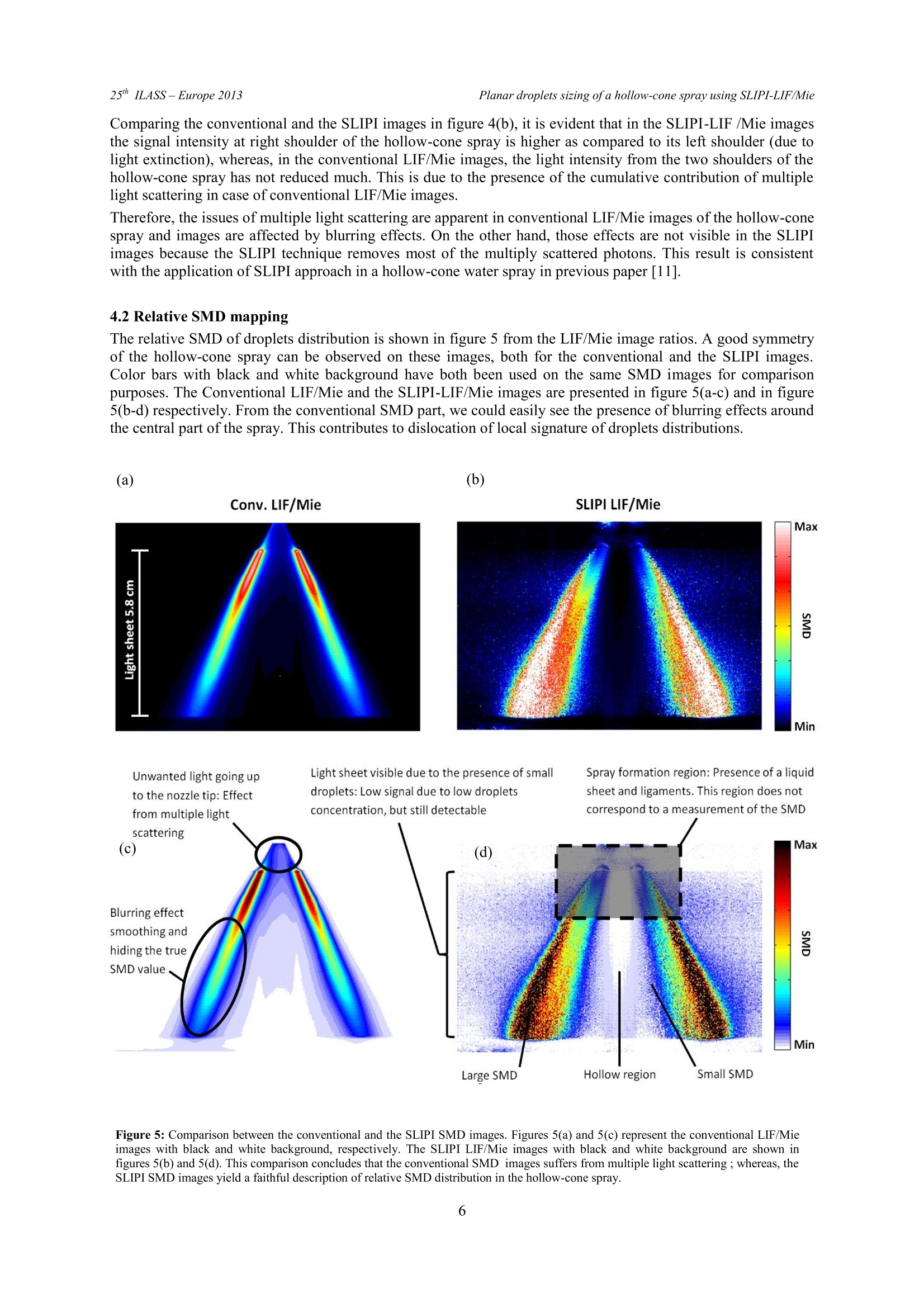
还剩5页未读,是否继续阅读?

产品配置单

北京欧兰科技发展有限公司为您提供《空心喷雾中液滴粒径检测方案(激光粒度仪)》,该方案主要用于其他中液滴粒径检测,参考标准--,《空心喷雾中液滴粒径检测方案(激光粒度仪)》用到的仪器有LaVision SprayMaster 喷雾成像测量系统
推荐专场


相关方案
更多
该厂商其他方案
更多