


采用美国Artium 公司的PDI-200型相位多普勒粒子干涉仪,对燃气轮机燃烧室新型双相空气喷射器喷雾的液滴粒径和SMD的空间分布及其与燃料的位置关系进行了实验测量研究。
方案详情

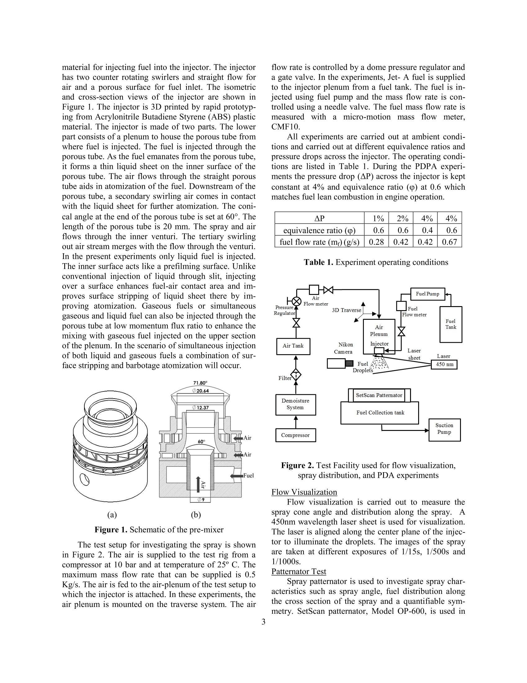
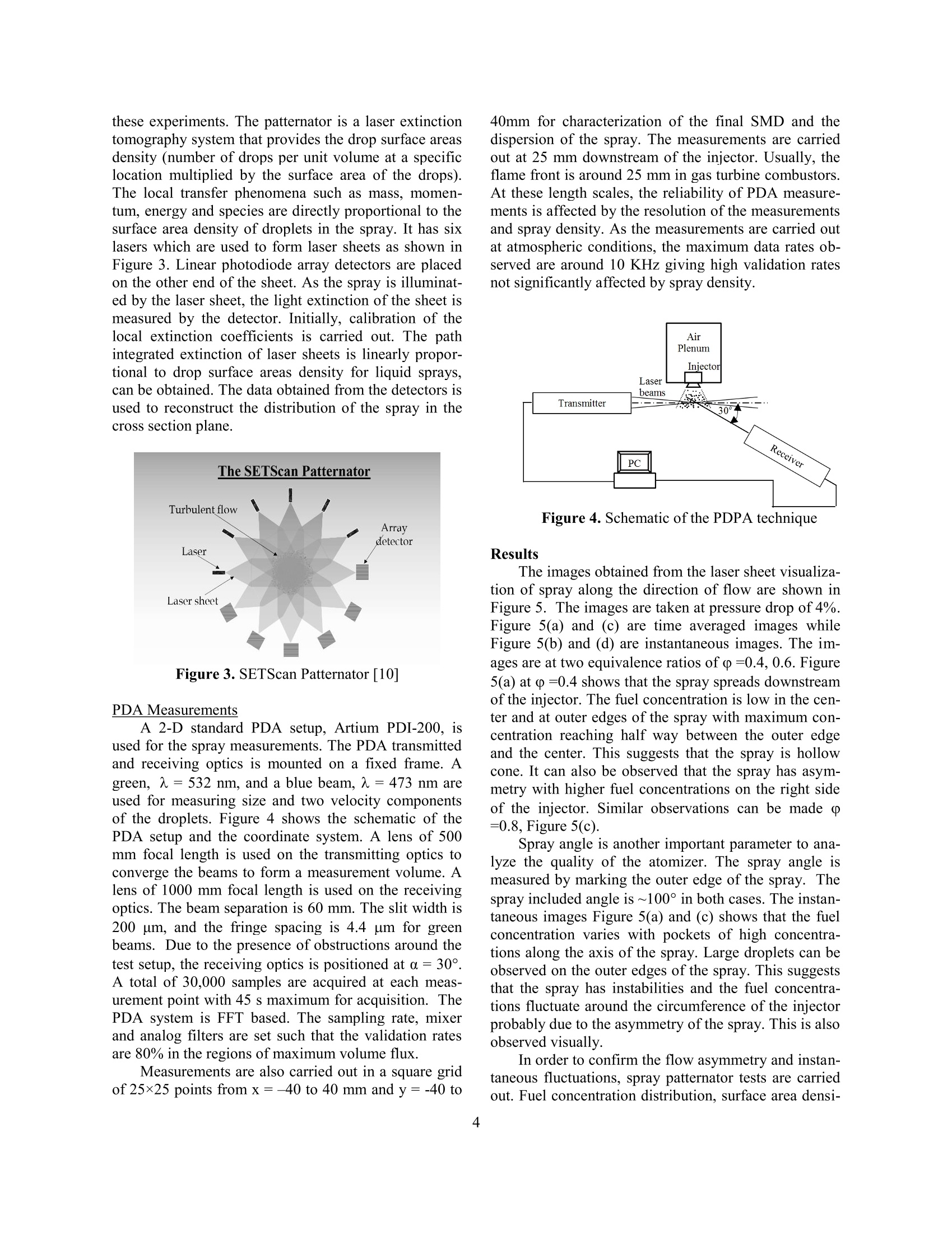
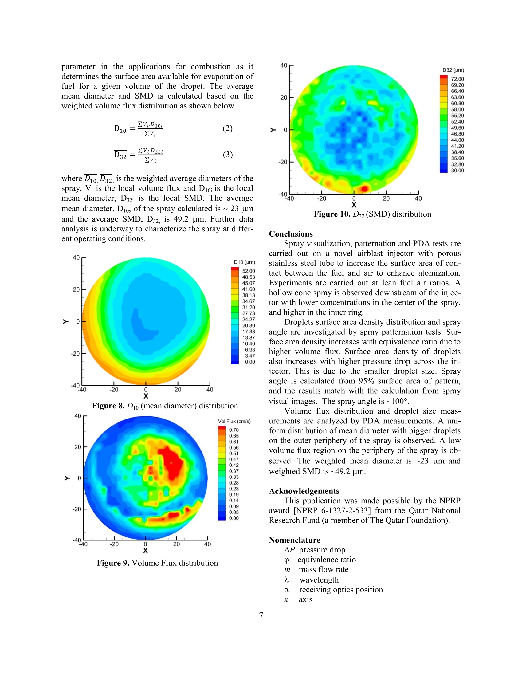
ResearchGateSee discussions,stats, and author profiles for this publication at: https://www.researchgate.net/publication/304626868 ILASS Americas 27th Annual Conference on Liquid Atomization and Spray Systems, Raleigh,NC, May 2015 Study of Spray Distribution and Fuel Placement from a Novel Dual Phase AirblastInjector for Gas Turbine Combustor Conference Paper· May 2015 CITATIONS READS 0 66 4 authors, including: Jianing Li University of Cincinnati 6 PUBLICATIONS 2 CITATIONS Mahmoud HamzaUniversity of Cincinnati7 PUBLICATIONS 4 CITATIONS SEE PROFILE SEE PROFILE Umesh Bhayaraju University of Cincinnati 22 PUBLICATIONS 66 CITATIONS SEE PROFILE Some of the authors of this publication are also working on these related projects: Project DIr koeln View project Study of Spray Distribution and Fuel Placement from a Novel Dual Phase Airblast Injectorfor Gas Turbine Combustor Jianing Li", Mahmoud Hamza, Umesh Bhayaraju and San-Mou Jeng Combustion Research Laboratory (CRL) Department of Aerospace Engineering and Engineering Mechanics University of Cincinnati 45220 USA Abstract A novel airblast injector is designed for gas turbine combustors. Unlike standard pressure swirl and prefilming/non-prefilming air blast atomizers, the novel injector has a porous stainless steel tube with 7 um porosity. The poroustube is used to inject the fuel between two air streams. The advantage of such an injector is that it can increase thesurface area of contact between the fuel and air by forming a thin liquid sheet along the circumference of the tubewhich will enhance the distribution the fuel more effectively, and produce a fine spray at engine idle conditions. Theinjector can also be used to inject simultaneously both liquid and gaseous fuels. An experimental approach is adopt-ed in the present study to characterize initially the spray and fuel placement emanating from this injector. The fuelinjector consists of two streams of air, viz. through inner section of the tube and another swirling stream mergingdownstream of the tube. Jet-A fuel is injected through the surface of the porous tube. Due to the permeability of thetube, a thin liquid sheet is produced along the tube which is atomized by the inner airstream by surface stripping ofthe liquid sheet. Further, a secondary breakup occurs downstream of the tube. The swirl vane angle and air split areselected to increase the amount of air through the tube and enhance the atomization. Flow visualization studies showa hollow conical spray. Patternator tests are carried out to study the fuel distribution and symmetry of the spray. Theresults show a hollow cone spray with asymmetric distribution of volume flux. Spray characterization is further car-ried out with PDPA at selected operating conditions. The measured SMD shows that the atomization is reasonablygood with wide fuel placement downstream of the atomizer at atmospheric conditions. Introduction The development of next generation aero-enginesis predominantly driven by NOx requirements. Thecurrent state of low NOx technology is governed by theimprovements made to the conventional Rich burn,Quick quench, Lean burn (RQL) combustor design.This approach has limited potential to cope with thestringent emission standards in future. To cater forthese standards, a revolutionary step has been takentowards lean combustor technology in United States.Similar approach is adopted in European Union withLowNOx programs from early 1990s. It's well understood that NOx formation is primari-ly governed by flame temperature and residence time ofthe species in the combustor. Lean combustor operateswith excess amount of air in the primary reaction zoneof the combustor at high power conditions. The excessair reduces the adiabatic flame temperature in the pri-mary zone reducing the NOx emissions. lDue to fastrate chemical kinetics, the length scales of the reactionzone are smaller thereby reducing combustor length andthe residence time for thermal NOx formation. Severaltechnologies have been developed like lean premixed(LP), lean premixed and pre-vaporized (LPP, LP (P)),dual annular staged combustion and concepts like GETAPS combustor [1]. Though these technologies arepromising, there are several issues associated with theseincluding static and dynamic flame stability problemsas well as auto ignition concerns. Atomization of fueland fuel-air mixing plays an important role in these leancombustor designs [2-7]. One of the other promising concepts of lean burncombustion is Lean Direct Injection (LDI), developedas an ultra-low NOx combustion scheme for future avi-ation gas turbines that has potential to reduce NOxemissions down to ppm level. In the LDI concept, theliquid fuel is directly injected into the combustionchamber of a gas turbine enabling rapid mixing with airat lean fuel-to-air ratios. The architecture of the LDIcombustor makes it compact with small residence time,low temperatures and significant size and weight reduc-tion of the combustor with lesser requirements for linercooling air tending towards convective cooling in theprimary zone thereby increasing combustion efficiency.LDI can operate on wide range of alternate fuels suchas FT process Jet Fuels, Hydropressed fuels, 100%blended fuels and biofuels. The LDI strategy facilitatesrapid and uniform premixed combustion under leanoperation, resulting in lower peak temperatures and lowresidence times. A rapid fuel evaporation process andfuel-air mixing is supposed to eliminate local hot spotsin this technology, thereby producing a uniform tem-perature distribution within the combustion chamber.The technology improves combustor exit temperature profile which will increase the life of the turbine com-ponents. While the concept of the LDI system is com-prehensive, achieving the required levels of perfor-mance can be challenging. Lean combustion systemsare prone to localized extinction and re-ignition. Thisalong with localized heat release zones can trigger axialacoustic modes in the combustor leading to combustioninstabilities [8, 9]. The instabilities results in significantincrease in the heat loads on the combustor liners po-tentially causing structural damage of the chamber.Furthermore, limitations in atomization, fuel-air mixingand evaporation will result in varied stoichiometric ra-tios in the reaction zone yielding higher than desiredNOx levels. Accordingly, there is an ongoing need inthe art to further develop LDI systems with novel injec-tion and fuel placement concepts that can achieve en-hanced atomization quality, increased fuel-air mixingrates, low levels of combustion instabilities, low pollu-tant and particulate formation, improved lean blow-outmargins and improved turndown ratio. To overcome the above mentioned issues with theprevious art in the LDI technology, new methods areunder consideration for improving the stability of theLDI combustors. One of the methods is to make theinjectors smaller and inject the fuel through large num-ber of injectors there by improving the mixing of fueland air. The advantage of splitting into smaller multipleswirler zones has benefit of effectively using the air foratomization. For larger swirlers, though excess air goesthrough the swirler, the amount of air contributing toatomization of the liquid fuel is far less and local AFRcan be low. By using multiple swirlers the overall AFRis evenly distributed. The amount of swirl strength andsize of the fuel injector/air-swirlers will be based on theflashback, LBO and auto ignition characteristics of theLDI combustor taking into consideration the require-ments for alternative fuels. The flame lengths will besmaller and the combustors length can be reduced giv-ing less residence time for NOx formation. However,for smaller injectors fuel injection/delivery strategy tothe injector is critical. Methods have to be developed toimprove the fuel-air contact surface and uniform fueldistribution in the injector. Furthering this technologyfor dual phase fuel injection (liquid and gas simultane-ously) and alternate fuels from the same injector, fuelinjection strategy is even more critical. In purview ofthis need, a novel injector is designed to improve thefuel injection delivery to the injector such that there isimproved atomization and mixing of fuel and air. Experimental Setup The experiments are carried out in CombustionResearch Lab (CRL), University of Cincinnati. In thepresent study, a novel injector is designed with porous material for injecting fuel into the injector. The injectorhas two counter rotating swirlers and straight flow forair and a porous surface for fuel inlet. The isometricand cross-section views of the injector are shown inFigure 1. The injector is 3D printed by rapid prototyp-ing from Acrylonitrile Butadiene Styrene (ABS) plasticmaterial. The injector is made of two parts. The lowerpart consists of a plenum to house the porous tube fromwhere fuel is injected. The fuel is injected through theporous tube. As the fuel emanates from the porous tube,it forms a thin liquid sheet on the inner surface oftheporous tube. The air flows through the straight poroustube aids in atomization of the fuel. Downstream of theporous tube, a secondary swirling air comes in contactwith the liquid sheet for further atomization. The coni-cal angle at the end of the porous tube is set at 60°. Thelength of the porous tube is 20 mm. The spray and airflows through the inner venturi. The tertiary swirlingout air stream merges with the flow through the venturi.In the present experiments only liquid fuel is injected.The inner surface acts like a prefilming surface. Unlikeconventional injection of liquid through slit, injectingover a surface enhances fuel-air contact area and im-proves surface stripping of liquid sheet there by im-proving atomization. Gaseous fuels or simultaneousgaseous and liquid fuel can also be injected through theporous tube at low momentum flux ratio to enhance themixing with gaseous fuel injected on the upper sectionof the plenum. In the scenario of simultaneous injectionof both liquid and gaseous fuels a combination of sur-face stripping and barbotage atomization will occur. Figure 1. Schematic of the pre-mixer The test setup for investigating the spray is shownin Figure 2. The air is supplied to the test rig from acompressor at 10 bar and at temperature of 25° C. Themaximum mass flow rate that can be supplied is 0.5Kg/s. The air is fed to the air-plenum of the test setup towhich the injector is attached. In these experiments, theair plenum is mounted on the traverse system. The air flow rate is controlled by a dome pressure regulator anda gate valve. In the experiments, Jet-A fuel is suppliedto the injector plenum from a fuel tank. The fuel is in-jected using fuel pump and the mass flow rate is con-trolled using a needle valve. The fuel mass flow rate ismeasured withamicro-motion mass flowmeter.CMF10. All experiments are carried out at ambient condi-tions and carried out at different equivalence ratios andpressure drops across the injector. The operating condi-tions are listed in Table 1. During the PDPA experi-ments the pressure drop (AP) across the injector is keptconstant at 4% and equivalence ratio (p) at 0.6 whichmatches fuel lean combustion in engine operation. AP 1% 2% 4% 4% equivalence ratio (() 0.6 0.6 0.4 0.6 fuel flow rate (mr)(g/s) 0.28 0.42 0.42 0.67 Table 1. Experiment operating conditions Figure 2. Test Facility used for flow visualization,spray distribution, and PDA experiments Flow Visualization Flow visualization is carried out to measure thespray cone angle and distribution along the spray. A450nm wavelength laser sheet is used for visualization.The laser is aligned along the center plane of the injec-tor to illuminate the droplets. The images of the sprayare taken at different exposures of 1/15s, 1/500s and1/1000s. Patternator Test Spray patternator is used to investigate spray char-acteristics such as spray angle, fuel distribution alongthe cross section of the spray and a quantifiable sym-metry. SetScan patternator, Model OP-600, is used in these experiments. The patternator is a laser extinctiontomography system that provides the drop surface areasdensity (number of drops per unit volume at a specificlocation multiplied by the surface area of the drops).The local transfer phenomena such as mass, momen-tum, energy and species are directly proportional to thesurface area density of droplets in the spray. It has sixlasers which are used to form laser sheets as shown inFigure 3. Linear photodiode array detectors are placedon the other end of the sheet. As the spray is illuminat-ed by the laser sheet, the light extinction of the sheet ismeasured by the detector. Initially, calibration of thelocal extinction coefficients is carried out. The pathintegrated extinction of laser sheets is linearly propor-tional to drop surface areas density for liquid sprays,can be obtained. The data obtained from the detectors isused to reconstruct the distribution of the spray in thecross section plane. Figure 3. SETScan Patternator [10] PDA Measurements A 2-D standard PDA setup, Artium PDI-200, isused for the spray measurements. The PDA transmittedand receiving optics is mounted on a fixed frame. Agreen, A= 532 nm, and a blue beam, =473 nm areused for measuring size and two velocity componentsof the droplets. Figure 4 shows the schematic of thePDA setup and the coordinate system. A lens of 500mm focal length is used on the transmitting optics toconverge the beams to form a measurement volume. Alens of 1000 mm focal length is used on the receivingoptics. The beam separation is 60 mm. The slit width is200 um, and the fringe spacing is 4.4 um for greenbeams. Due to the presence of obstructions around thetest setup, the receiving optics is positioned at a=30°.A total of 30,000 samples are acquired at each meas-urement point with 45 s maximum for acquisition. ThePDA system is FFT based. The sampling rate, mixerand analog filters are set such that the validation ratesare 80% in the regions of maximum volume flux. Measurements are also carried out in a square gridof 25×25 points from x=-40 to 40 mm and y=-40 to 40mm for characterization of the final SMD and thedispersion of the spray. The measurements are carriedout at 25 mm downstream of the injector. Usually, theflame front is around 25 mm in gas turbine combustors.At these length scales, the reliability of PDA measure-ments is affected by the resolution of the measurementsand spray density. As the measurements are carried outat atmospheric conditions, the maximum data rates ob-served are around 10 KHz giving high validation ratesnot significantly affected by spray density. Figure 4. Schematic of the PDPA technique Results The images obtained from the laser sheet visualiza-tion of spray along the direction of flow are shown inFigure 5. The images are taken at pressure drop of 4%.Figure 5(a) and (c) are time averaged images whileFigure 5(b) and (d) are instantaneous images. The im-ages are at two equivalence ratios of p=0.4, 0.6. Figure5(a) at (=0.4 shows that the spray spreads downstreamof the injector. The fuel concentration is low in the cen-ter and at outer edges of the spray with maximum con-centration reaching half way between the outer edgeand the center. This suggests that the spray is hollowcone. It can also be observed that the spray has asym-metry with higher fuel concentrations on the right sideof the injector. Similar observations can be made o=0.8, Figure 5(c). Spray angle is another important parameter to ana-lyze the quality of the atomizer. The spray angle ismeasured by marking the outer edge of the spray. Thespray included angle is ~100° in both cases. The instan-taneous images Figure 5(a) and(c) shows that the fuelconcentration varies with pockets of high concentra-tions along the axis of the spray. Large droplets can beobserved on the outer edges of the spray. This suggeststhat the spray has instabilities and the fuel concentra-tions fluctuate around the circumference of the injectorprobably due to the asymmetry of the spray. This is alsoobserved visually. In order to confirm the flow asymmetry and instan-taneous fluctuations, spray patternator tests are carriedout. Fuel concentration distribution. surface area densi- ty, symmetry of the spray and spray angle calculationare obtained from spray patternator tests. Figure 5. Flow visualization of spray (AP=4%) Spray patternator tests are carried out at two equiv-alence ratios, two pressure drop conditions and at 12.7mm and 19.05 mm downstream of the atomizer. Table2 shows the operating conditions and the spray anglemeasured from the patternator experiments. In Case d,spray angle measured from patternator matches with thecalculation result from spray visualization. case pressuredrop O h(mm) spray angle(degree) a 2% 0.6 19.05 115.8 b 2% 0.8 19.05 111.54 c 2% 0.6 12.7 118.8 d 4% 0.6 12.7 120.7 Table 2. Results of spray angle calculation Figure 6 (a) and (b) represent droplets surface areadensity distribution at 19.05 mm downstream of atom-izer. Figure 6 (c) and (d) represents droplets surfacearea density distribution at 12.7 mm downstream of theatomizer. The droplets surface area density is the prod-uct of the droplets surface area and the counts of drop-lets per unit volume. The surface area density is a sig-nificance parameter in combustion application due tothe high correlation to local evaporation rate. Fuel con-centration distribution is also proportional to dropletssurface area density which is represented in Figure 6.Figure 6 (a) and 6 (b) are at pressure drop of 2% and atequivalence ratio p=0.6 and p =0.8. As it is evident,the droplets spray surface area density increases withequivalence ratio. This is primary due to the increase infuel flow rates. An increase in fuel rates leads to highervolume flux and higher droplet density. Figure 6 (C) and6 (d) exemplifies that at same equivalence ratio condi-tion, higher droplet surface area density and fuel con-centration distribution can be obtained by increasingpressure drop. As the pressure drop across the injector is increasing, the velocity of air is increasing leading toincrease in surface stripping of liquid sheet on the po-rous tube. The increased surface stripping improvesatomization and much finer droplets are formed. Thesmaller droplets have higher surface to volume ratiothere by increasing the droplets surface area even whenthe mass flow rate of fuel is kept constant. Figure 6 (a)and 6 (C) shows that as downstream distance increasesfrom the injector, the spray expands. In all of the four cases discussed above, a hollowcone spray is observed, as evident from the contourplots, with lower fuel concentration in the center of thespray shown by green color, and higher concentrationdistribution in the form of an inner ring shown by redcolor. This is due to the atomization of the liquid sheetwhich is produced along the inner circumference of theporous tube. The liquid sheet is atomized by air enter-ing through the porous tube through surface strippingphenomena [11]. Similar to the observations made in Figure 5, thespray is asymmetric with higher concentrations on up-per right side of the spray. It is observed that some ofthe gaps between the vanes of the inner swirler areblocked during 3d printing of the injector causing non-uniform distribution of air leading to higher spray con-centrations on the right side of the atomizer (a) 2% pressure drop, p=0.6, 19.05mm downstream (c) 2% pressure drop, p=0.6, 12.7mm downstream (d) 4% pressure drop,p=0.6, 12.7mm downstream Figure 6. Droplet surface area density distribution Spray angle is calculated from the patternator data.It is defined from the distance from the atomizer to thelocation of spray pattern and the radius of spray patternwhich is calculated from 95% surface area of pattern.The calculation is given in Equation 1 and shown inFigure 7. The results of spray angle are listed in Table 2.Under same operation condition, spray angle remainssame as downstream distance changes. Also as pressuredrop stays same, higher equivalence ratio results insmaller spray angle. Figure 7. Spray angle Calculation PDA Measurements Droplet size measurements are carried out to accessthe spray distribution downstream of the injector. Themeasurmenet grid is rectangular. The data obtained isfurther processed and interpolated into a circular grid.The data is filtered such that there is minimum of 5 Hzdata rates at any given measurement point. The data isprocessed with Artium software. PDA measurementsare carried out at AP=4% and, p=0.6 condition.Figure 8 shows the contour plot of mean diameter D10.The contour plot shows a uniform distribution of meandiameter with higher droplet diameters on the outerperiphery of the spray. Further the mean diameter ishigher on the right side. This is, as explained in theearlier sections, due to the higher volume flux on theride side of the spray. This is also evident from thevolume flux data obtained from PDA measurments.Figure 9 shows volume flux distribution obtained fromthe PDA measurements. As can be observed the volumeflux is higher on the right side of the spray. The reasonfor higher volume flux is already explained in theearlier section. A low volume flux region is observedon the periphery of the spray which is expected. Furthera concentric ring of low volume flux around the highervolume flux region is observed which is not observed inthe patternator data. This is not clear from the PDA dataacquired. Further PDA data analysis needs to carriedout to explain the difference between volume fluxdistribution between PDA and Patternator. Figure 10, shows the contour plot of SMD (SauterMean Diameter) D32. Similar to Dio, the D32 shows auniform distribution in the spray with marginally higherdiameter on the right side of the spray. Also, higherdroplet diameters are observed on the outer periphery ofthe spray which is expected. The uniformity in thedistribution is mainly to the process of the atomization.The atomization occurs due to the surface stripping ofthe liqiud sheet [11]. In the present scenario, as theliquid eminates from the micro porous, the fuel isspread uniformly on the inner walls of the porous tube(in comparison the liquid sheet from a slit of anystandard airblast atomizer depends on themanufacturing tolerances ofthe slit). SMD is important parameter in the applications for combustion as itdetermines the surface area available for evaporation offuel for a given volume of the dropet. The averagemean diameter and SMD is calculated based on theweighted volume flux distribution as shown below. where D1o, D32, is the weighted average diameters of thespray, Vi is the local volume flux and D10i is the localmean diameter, D32i is the local SMD. The averagemean diameter, D10, of the spray calculated is ~ 23 umand the average SMD, D32, is 49.2 um. Further dataanalysis is underway to characterize the spray at differ-ent operating conditions. Figure 8. Dio (mean diameter) distribution Figure 9. Volume Flux distribution Figure 10. D32 (SMD) distribution Conclusions Spray visualization, patternation and PDA tests arecarried out on a novel airblast injector with porousstainless steel tube to increase the surface area of con-tact between the fuel and air to enhance atomization.Experiments are carried out at lean fuel air ratios. Ahollow cone spray is observed downstream of the injec-tor with lower concentrations in the center of the spray,and higher in the inner ring. Droplets surface area density distribution and sprayangle are investigated by spray patternation tests. Sur-face area density increases with equivalence ratio due tohigher volume flux. Surface area density of dropletsalso increases with higher pressure drop across the in-jector. This is due to the smaller droplet size. Sprayangle is calculated from 95% surface area of pattern,and the results match with the calculation from sprayvisual images. The spray angle is ~100°. Volume flux distribution and droplet size meas-urements are analyzed by PDA measurements. A uni-form distribution of mean diameter with bigger dropletson the outer periphery of the spray is observed. A lowvolume flux region on the periphery of the spray is ob-served. The weighted mean diameter is ~23 um andweighted SMD is ~49.2 um. Acknowledgements This publication was made possible by the NPRPaward [NPRP 6-1327-2-533] from the Qatar NationalResearch Fund (a member of The Qatar Foundation). Nomenclature AP pressure drop equivalence ratiom mass flow rate wavelength receiving optics position axis atomizer height spray angle r radius of spray pattern diameter volume flux Subscripts fuel local mean DoSMD Superscripts average References 1.Michael J. Foust, et. al. "Development of the GEAviation Low Emissions TAPS Combustor forNext Generation Aircraft Engines", 50th AIAAAerospace Meeting, AIAA 2012-0936, Nashville,Tennessee. 2. Yongqiang Fu, Jun Cai, Ahmed Elkady and San-Mou Jeng, "Fuel and Equivalence Ratio Effects onSpray Combustion of a Counter-rotating Swirler",AIAA 2005-0354,43rd AIAA Aerospace SciencesMeeting and Exhibit, Reno, Nevada, Jan. 10-13,2005. 3. Tacina, R. R., Wey, C., Choi, K.J., Flame TubeNOxEmissions Using a Lean-Direct-Wall-Injection Combustor Concept, Tm-2001-211105,AIAA2001-3271.presented att37thAI-AA/ASME/SAE/ASEE Joint Propulsion Confer-ence & Exhibit, July 8-11, 2001, Salt Lake City,Utah. 4. Tacina, R., Lee, P., Wey, C., "A Lean-Direct-Injection Combustor Using a 9 Point Swirl-VenturiFuel Injector," ISABE-2005-1106, Munich, Ger-many 5. Tacina, R., Mansour, A., Partelow, L., Wey, C.,"Experimental Sector and Flame-Tube Evaluationsof a Multipoint Integrated Module Concept forLowEmissionn Combustors" GT-2004-53263.ASME Turbo Expo 2004, Vienna, Austria. 6. Tacina, R., Wey, C., Laing, P., and Mansour, A.,"Sector TTeesststs of aLow-NOx, Lean-Direct-Injection, MultiPoint Integrated Module Combus-tor Concept," GT-2002-30089, ASME Turbo Expo2002,Amsterdam, the Netherlands. 7. Chi-Ming Lee, "NASA Low NOx Fuel FlexibleCombustor Technical Challenges", NASA GreenAviation Summit, September 8-9,2010. 8. Prachi Rojatkar, Milind Jog, San-Mou Jeng and Yi-Huan Kao, "Effect of Swirler Offset on Aerody- namics's (ofMultiswirlleerr Arrays", GGTT--26236,Dusseldorf, Germany, June 16-20,2014. 9. Y. Huanga and V. Yang, "Dynamics and stabilityof lean-premixedswirl-stabilized combustion"Progress in Energy and Combustion Science, vol.35, pp.293-364,2009. 10. Setscan OP-600 Manual 11. Umesh Bhayaraju and Christoph Hassa,“Analysisof Liquid sheet breakup of prefilming and non-prefilming airblast atomisers”, Atomization. andSprays, December, 2009 All content following this page was uploaded by Jianing Li on June he user has requested enhancement of the downloaded file. Corresponding author: lijg@mail.uc.edu A novel airblast injector is designed for gas turbine combustors. Unlike standard pressure swirl and prefilming/non-prefilming air blast atomizers, the novel injector has a porous stainless steel tube with 7um porosity. The porous tube is used to inject the fuel between two air streams. The advantage of such an injector is that it can increase the surface area of contact between the fuel and air by forming a thin liquid sheet along the circumference of the tube which will enhance the distribution the fuel more effectively, and produce a fine spray at engine idle conditions. The injector can also be used to inject simultaneously both liquid and gaseous fuels. An experimental approach is adopted in the present study to characterize initially the spray and fuel placement emanating from this injector. The fuel injector consists of two streams of air, viz. through inner section of the tube and another swirling stream merging downstream of the tube. Jet-A fuel is injected through the surface of the porous tube. Due to the permeability of the tube, a thin liquid sheet is produced along the tube which is atomized by the inner airstream by surface stripping of the liquid sheet. Further, a secondary breakup occurs downstream of the tube. The swirl vane angle and air split are selected to increase the amount of air through the tube and enhance the atomization. Flow visualization studies show a hollow conical spray. Patternator tests are carried out to study the fuel distribution and symmetry of the spray. The results show a hollow cone spray with asymmetric distribution of volume flux. Spray characterization is further car-ried out with PDPA at selected operating conditions. The measured SMD shows that the atomization is reasonably good with wide fuel placement downstream of the atomizer at atmospheric conditions.
确定


还剩7页未读,是否继续阅读?

产品配置单

北京欧兰科技发展有限公司为您提供《新型双相空气喷射器中SMD,液滴粒径分布检测方案(激光干涉仪)》,该方案主要用于其他中SMD,液滴粒径分布检测,参考标准--,《新型双相空气喷射器中SMD,液滴粒径分布检测方案(激光干涉仪)》用到的仪器有激光相位多普勒干涉仪LDV,PDI,PDPA,PDA
推荐专场


相关方案
更多
该厂商其他方案
更多