


采用LaVision公司的图像增强器IRO,DaVis软件,可调谐染料激光器,可编程时间控制单元等,搭建了一套平面激光诱导荧光和粒子成像测速同步联合测量系统。并利用该系统对旋流对流动结构和湍流射流中混合过程的影响进行了实验和理论研究。
方案详情

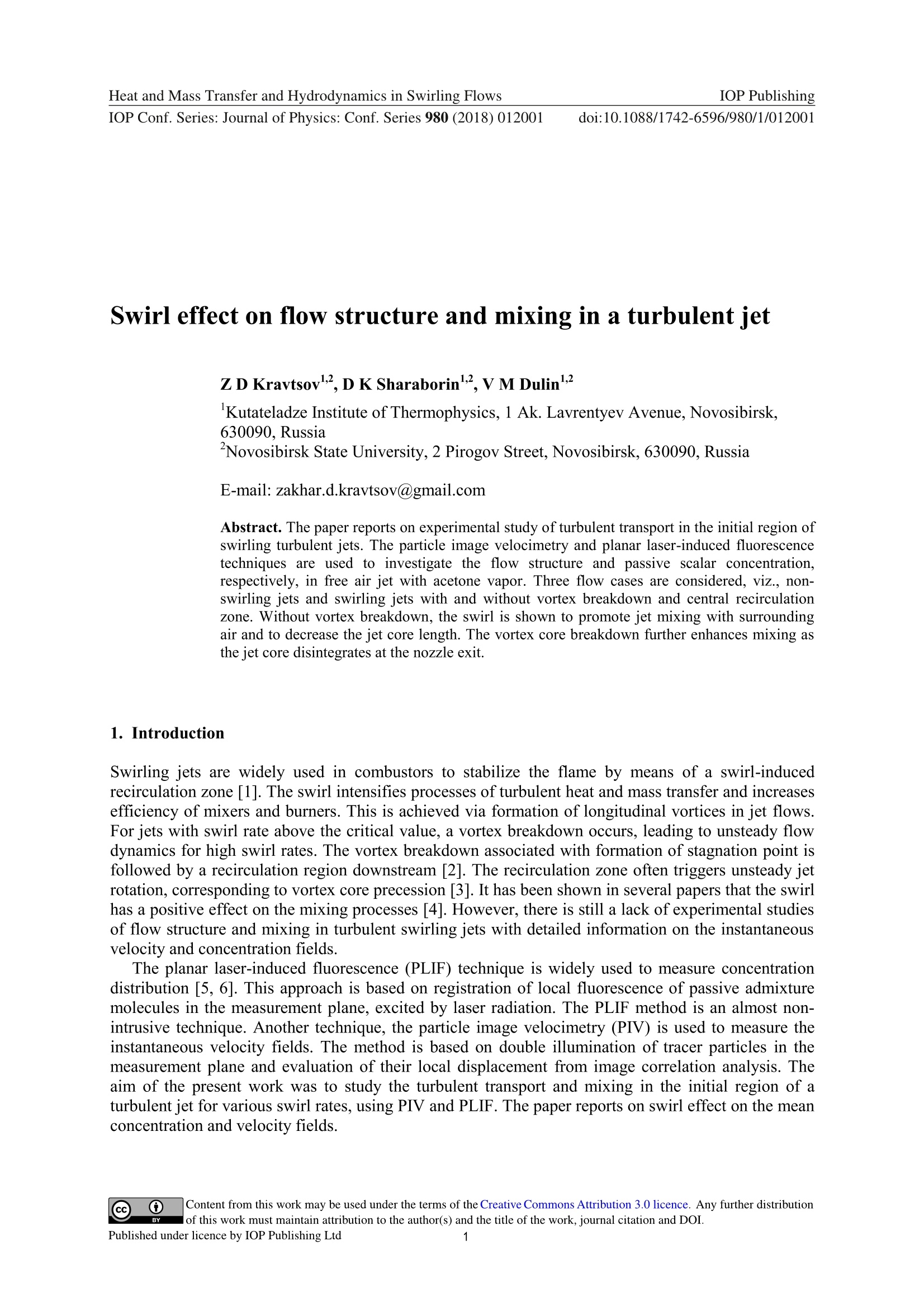
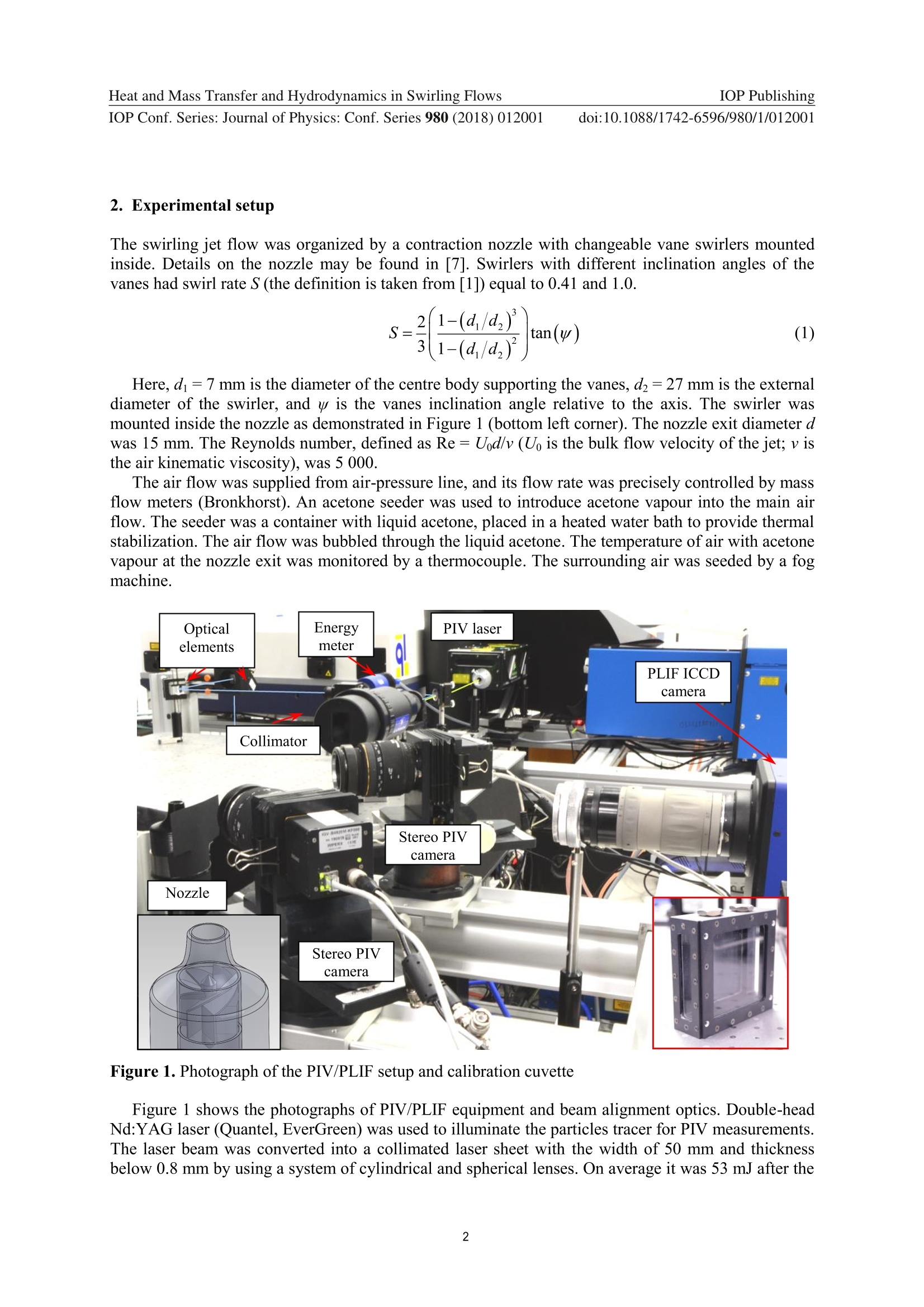
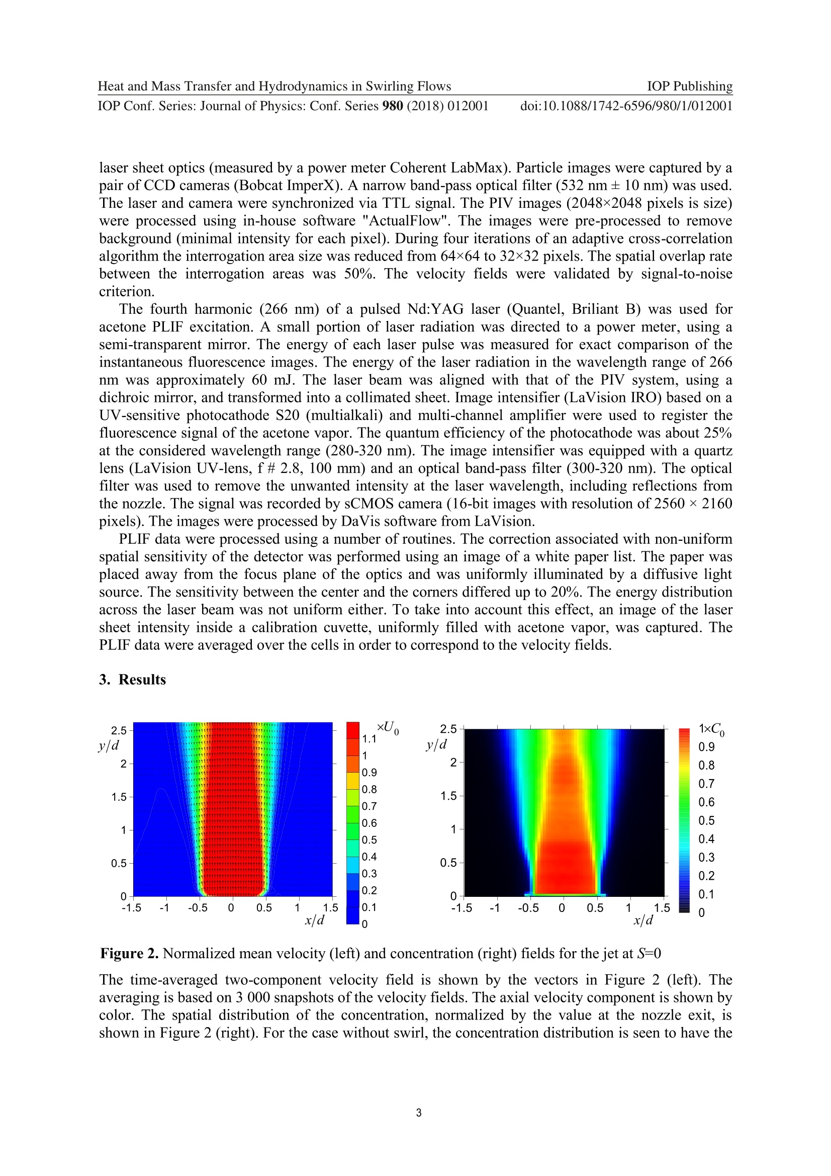
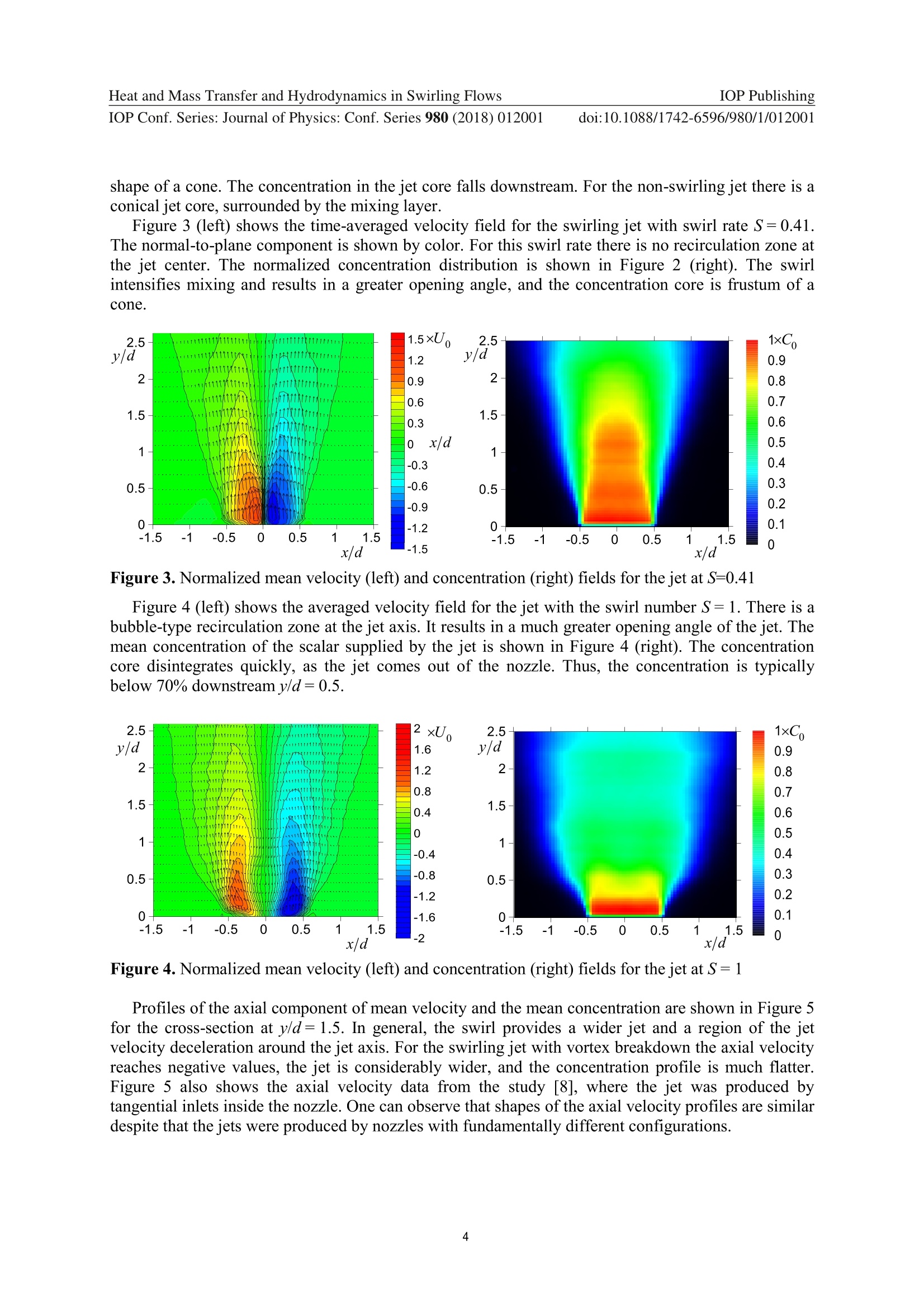
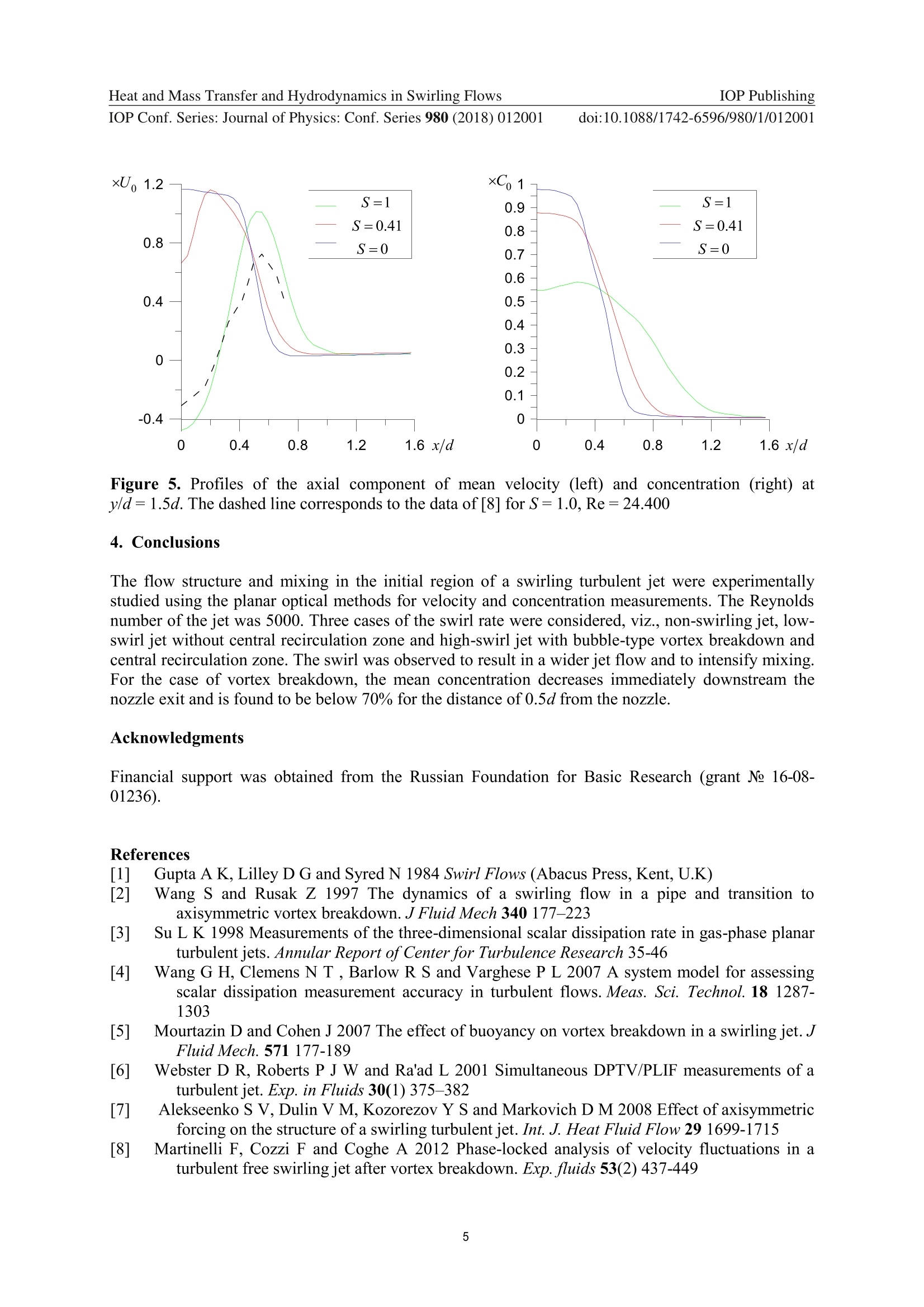
Journal of Physics: Conference Series IOP PublishingHeat and Mass Transfer and Hydrodynamics in Swirling FlowsIOP Conf. Series: Journal of Physics: Conf. Series 980 (2018) 012001 PAPER·OPEN ACCESS Related content Swirl effect on flow structure and mixing in aturbulent jet TMIOP ebooks Bringing you innovative digital publishing with leading voicesto create your essential collection of books in STEM research. Start exploring the collection - download the first chapter ofevery title for free. doi:10.1088/1742-6596/980/1/012001 Swirl effect on flow structure and mixing in a turbulent jet Z D Kravtsov ,D K Sharaborin,VM Dulin Kutateladze Institute of Thermophysics, 1 Ak. Lavrentyev Avenue, Novosibirsk,630090, Russia Novosibirsk State University, 2 Pirogov Street, Novosibirsk, 630090, Russia E-mail: zakhar.d.kravtsov@gmail.com Abstract. The paper reports on experimental study of turbulent transport in the initial region ofswirling turbulent jets. The particle image velocimetry and planar laser-induced fluorescencetechniques are used to investigate the flow structure and passive scalar concentration,respectively, in free air jet with acetone vapor. Three flow cases are considered, viz., non-swirling jets and swirling jets with and without vortex breakdown and central recirculationzone. Without vortex breakdown, the swirl is shown to promote jet mixing with surroundingair and to decrease the jet core length. The vortex core breakdown further enhances mixing asthe jet core disintegrates at the nozzle exit. 1. Introduction Swirling jets are widely used in combustors to stabilize the flame by means of a swirl-inducedrecirculation zone [1]. The swirl intensifies processes of turbulent heat and mass transfer and increasesefficiency of mixers and burners. This is achieved via formation of longitudinal vortices in jet flows.For jets with swirl rate above the critical value, a vortex breakdown occurs, leading to unsteady flowdynamics for high swirl rates. The vortex breakdown associated with formation of stagnation point isfollowed by a recirculation region downstream [2]. The recirculation zone often triggers unsteady jetrotation, corresponding to vortex core precession [3]. It has been shown in several papers that the swirlhas a positive effect on the mixing processes [4]. However, there is still a lack of experimental studiesof flow structure and mixing in turbulent swirling jets with detailed information on the instantaneousvelocity and concentration fields. The planar laser-induced fluorescence (PLIF) technique is widely used to measure concentrationdistribution [5, 6]. This approach is based on registration of local fluorescence of passive admixturemolecules in the measurement plane, excited by laser radiation. The PLIF method is an almost non-intrusive technique. Another technique, the particle image velocimetry (PIV) is used to measure theinstantaneous velocity fields. The method is based on double illumination of tracer particles in themeasurement plane and evaluation of their local displacement from image correlation analysis. Theaim of the present work was to study the turbulent transport and mixing in the initial region of aturbulent jet for various swirl rates, using PIV and PLIF. The paper reports on swirl effect on the meanconcentration and velocity fields. ( C o n tent f r om this work may be used under the terms of the Cre ativ e Co m mon s At tributio n 3.0 l i cenc e . Any f urther distributionl of this work must maintain attribution to the author(s) and t he t itle of the work, journal citation and DOI. ) IOP Conf. Series: Journal of Physics: Conf. Series 980 (2018) 012001 doi:10.1088/1742-6596/980/1/012001 2. Experimental setup The swirling jet flow was organized by a contraction nozzle with changeable vane swirlers mountedinside. Details on the nozzle may be found in [7]. Swirlers with different inclination angles of thevanes had swirl rate S (the definition is taken from [1]) equal to 0.41 and 1.0. Here, d=7 mm is the diameter of the centre body supporting the vanes, dz=27 mm is the externaldiameter of the swirler, and w is the vanes inclination angle relative to the axis. The swirler wasmounted inside the nozzle as demonstrated in Figure 1 (bottom left corner). The nozzle exit diameter dwas 15 mm. The Reynolds number, defined as Re=Ud/v (U is the bulk flow velocity of the jet; visthe air kinematic viscosity), was 5 000. The air flow was supplied from air-pressure line, and its flow rate was precisely controlled by massflow meters (Bronkhorst). An acetone seeder was used to introduce acetone vapour into the main airflow. The seeder was a container with liquid acetone, placed in a heated water bath to provide thermalstabilization. The air flow was bubbled through the liquid acetone. The temperature of air with acetonevapour at the nozzle exit was monitored by a thermocouple. The surrounding air was seeded by a fogmachine. Figure 1. Photograph of the PIV/PLIF setup and calibration cuvette Figure 1 shows the photographs of PIV/PLIF equipment and beam alignment optics. Double-headNd:YAG laser (Quantel, EverGreen) was used to illuminate the particles tracer for PIV measurements.The laser beam was converted into a collimated laser sheet with the width of 50 mm and thicknessbelow 0.8 mm by using a system of cylindrical and spherical lenses. On average it was 53 mJ after the laser sheet optics (measured by a power meter Coherent LabMax). Particle images were captured by apair of CCD cameras (Bobcat ImperX). A narrow band-pass optical filter (532 nm± 10 nm) was used..The laser and camera were synchronized via TTL signal. The PIV images (2048×2048 pixels is size)were processed using in-house software "ActualFlow". The images were pre-processed to removebackground (minimal intensity for each pixel). During four iterations of an adaptive cross-correlationalgorithm the interrogation area size was reduced from 64x64 to 32x32 pixels. The spatial overlap ratebetween the interrogation areas was 50%. The velocity fields were validated by signal-to-noisecriterion. The fourth harmonic (266 nm) of a pulsed Nd:YAG laser (Quantel, Briliant B) was used foracetone PLIF excitation. A small portion of laser radiation was directed to a power meter, using asemi-transparent mirror. The energy of each laser pulse was measured for exact comparison of theinstantaneous fluorescence images. The energy of the laser radiation in the wavelength range of 266nm was approximately 60 mJ. The laser beam was aligned with that of the PIV system, using adichroic mirror, and transformed into a collimated sheet. Image intensifier (LaVision IRO) based on aUV-sensitive photocathode S20 (multialkali) and multi-channel amplifier were used to register thefluorescence signal of the acetone vapor. The quantum efficiency of the photocathode was about 25%at the considered wavelength range (280-320 nm). The image intensifier was equipped with a quartzlens (LaVision UV-lens, f# 2.8, 100 mm) and an optical band-pass filter (300-320 nm). The opticalfilter was used to remove the unwanted intensity at the laser wavelength, including reflections fromthe nozzle. The signal was recorded by sCMOS camera (16-bit images with resolution of 2560×2160pixels). The images were processed by DaVis software from LaVision. PLIF data were processed using a number of routines. The correction associated with non-uniformspatial sensitivity of the detector was performed using an image of a white paper list. The paper wasplaced away from the focus plane of the optics and was uniformly illuminated by a diffusive lightsource. The sensitivity between the center and the corners differed up to 20%. The energy distributionacross the laser beam was not uniform either. To take into account this effect, an image of the lasersheet intensity inside a calibration cuvette, uniformly filled with acetone vapor, was captured. ThePLIF data were averaged over the cells in order to correspond to the velocity fields. 3. Results Figure 2. Normalized mean velocity (left) and concentration (right) fields for the jet at S=0 The time-averaged two-component velocity field is shown by the vectors in Figure 2 (left). Theaveraging is based on 3 000 snapshots of the velocity fields. The axial velocity component is shown bycolor. The spatial distribution of the concentration, normalized by the value at the nozzle exit, isshown in Figure 2 (right). For the case without swirl, the concentration distribution is seen to have the shape of a cone. The concentration in the jet core falls downstream. For the non-swirling jet there is aconical jet core, surrounded by the mixing layer. Figure 3 (left) shows the time-averaged velocity field for the swirling jet with swirl rate S=0.41.The normal-to-plane component is shown by color. For this swirl rate there is no recirculation zone atthe jet center. The normalized concentration distribution is shown in Figure 2 (right). The swirlintensifies mixing and results in a greater opening angle, and the concentration core is frustum of acone. Figure 3. Normalized mean velocity (left) and concentration (right) fields for the jet at S=0.41 Figure 4 (left) shows the averaged velocity field for the jet with the swirl number S=1. There is abubble-type recirculation zone at the jet axis. It results in a much greater opening angle of the jet. Themean concentration of the scalar supplied by the jet is shown in Figure 4 (right). The concentrationcore disintegrates quickly, as the jet comes out of the nozzle. Thus, the concentration is typicallybelow 70% downstreamy/d=0.5. Figure 4. Normalized mean velocity (left) and concentration (right) fields for the jet at S=1 Profiles of the axial component of mean velocity and the mean concentration are shown in Figure 5for the cross-section at y/d=1.5. In general, the swirl provides a wider jet and a region of the jevelocity deceleration around the jet axis. For the swirling jet with vortex breakdown the axial velocityreaches negative values, the jet is considerably wider, and the concentration profile is much flatter.Figure 5 also shows the axial velocity data from the study [8], where the jet was produced bytangential inlets inside the nozzle. One can observe that shapes of the axial velocity profiles are similardespite that the jets were produced by nozzles with fundamentally different configurations. Figure 5. Profiles of the axial component of mean velocity (left) and concentration (right) aty/d=1.5d. The dashed line corresponds to the data of [8] for S=1.0,Re=24.400 4. Conclusions The flow structure and mixing in the initial region of a swirling turbulent jet were experimentallystudied using the planar optical methods for velocity and concentration measurements. The Reynoldsnumber of the jet was 5000. Three cases of the swirl rate were considered, viz., non-swirling jet, low-swirl jet without central recirculation zone and high-swirl jet with bubble-type vortex breakdown andcentral recirculation zone. The swirl was observed to result in a wider jet flow and to intensify mixing.For the case of vortex breakdown, the mean concentration decreases immediately downstream thenozzle exit and is found to be below 70% for the distance of 0.5d from the nozzle. Acknowledgments Financial support was obtained from the Russian Foundation for Basic Research (grant Ne 16-08-01236). References Gupta A K, Lilley D G and Syred N 1984 Swirl Flows (Abacus Press, Kent, U.K Wang S and Rusak Z 1997 The dynamics of a swirling flow in a pipe and transition tcaxisymmetric vortex breakdown. J Fluid Mech 340 177-223 [31 Su L K 1998 Measurements of the three-dimensional scalar dissipation rate in gas-phase planarturbulent jets. Annular Report ofCenter for Turbulence Research 35-46 [4] Wang G H, Clemens N T, Barlow R S and Varghese P L 2007 A system model for assessingscalar dissipation measurement accuracy in turbulent flows. Meas. Sci. Technol. 18 1287-1303 [51 Mourtazin D and Cohen J 2007 The effect of buoyancy on vortex breakdown in a swirling jet. JFluid Mech.571 177-189 [6] Webster D R, Roberts P J W and Ra'ad L 2001 Simultaneous DPTV/PLIF measurements of aturbulent jet. Exp. in Fluids 30(1)375-382 Alekseenko S V, Dulin V M, Kozorezov Y S and Markovich D M 2008 Effect of axisymmetricforcing on the structure of a swirling turbulent jet. Int. J. Heat Fluid Flow 29 1699-1715 [8R Martinelli F, Cozzi F and Coghe A 2012 Phase-locked analysis of velocity fluctuations in aturbulent free swirling jet after vortex breakdown. Exp. fluids 53(2) 437-449 This content was downloaded from IP address on at Published under licence by IOP Publishing Ltd The paper reports on experimental study of turbulent transport in the initial region ofswirling turbulent jets. The particle image velocimetry and planar laser-induced fluorescencetechniques are used to investigate the flow structure and passive scalar concentration,respectively, in free air jet with acetone vapor. Three flow cases are considered, viz., nonswirling jets and swirling jets with and without vortex breakdown and central recirculationzone. Without vortex breakdown, the swirl is shown to promote jet mixing with surroundingair and to decrease the jet core length. The vortex core breakdown further enhances mixing as the jet core disintegrates at the nozzle exit.
确定

还剩4页未读,是否继续阅读?

产品配置单


北京欧兰科技发展有限公司为您提供《射流中PIV PLIF检测方案(CCD相机)》,该方案主要用于其他中PIV PLIF检测,参考标准--,《射流中PIV PLIF检测方案(CCD相机)》用到的仪器有LaVision IRO 图像增强器、德国LaVision PIV/PLIF粒子成像测速场仪、PLIF平面激光诱导荧光火焰燃烧检测系统、LaVision DaVis 智能成像软件平台
推荐专场


相关方案
更多
该厂商其他方案
更多