


方案详情
文
采用LaVision公司的PLIF平面激光诱导荧光火焰自由基分析测量系统,对中等尺度燃烧器阵列燃烧是产生的甲醛,CH,OH等自由基浓度的空间分布进行了测量研究。
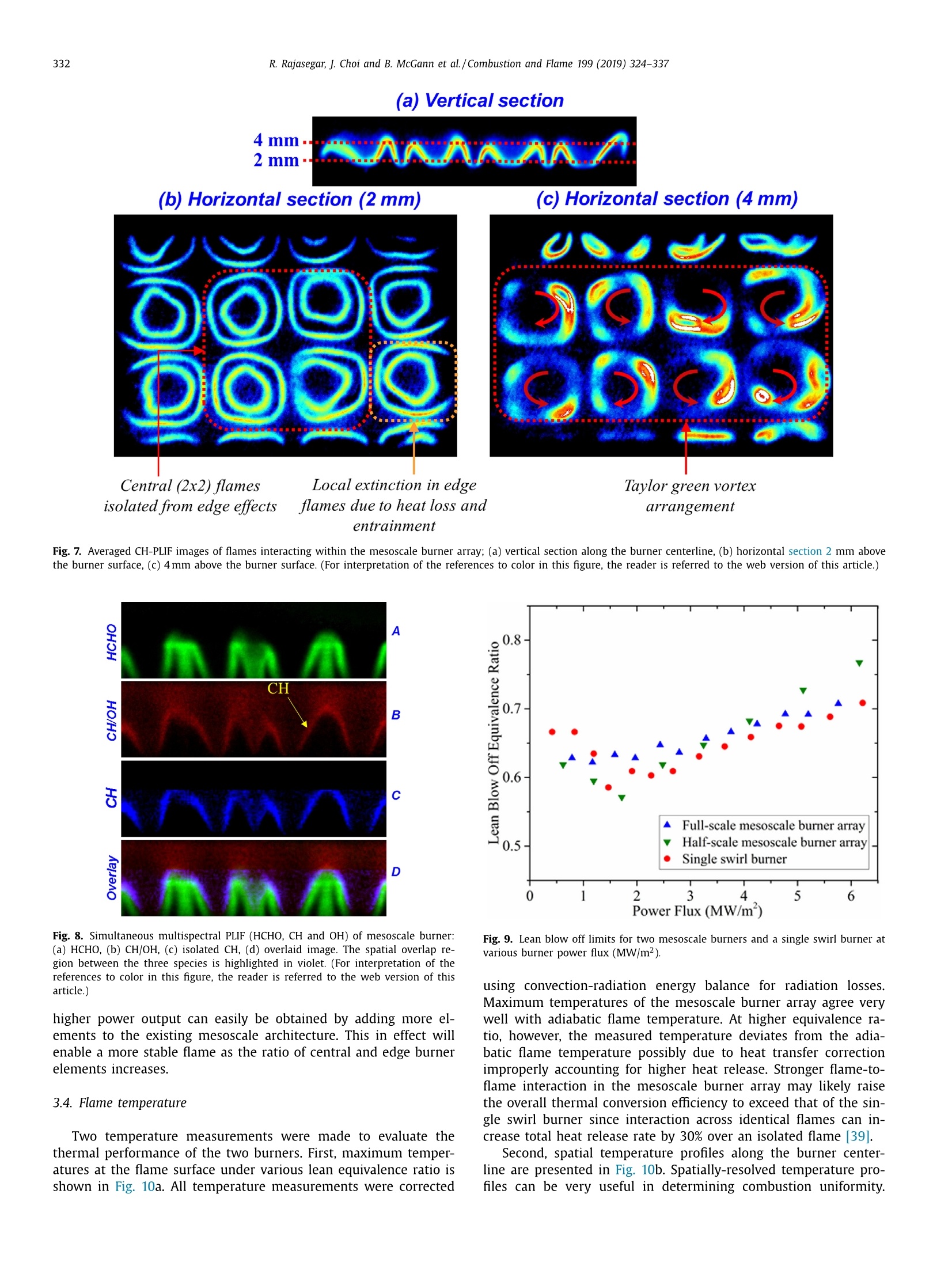
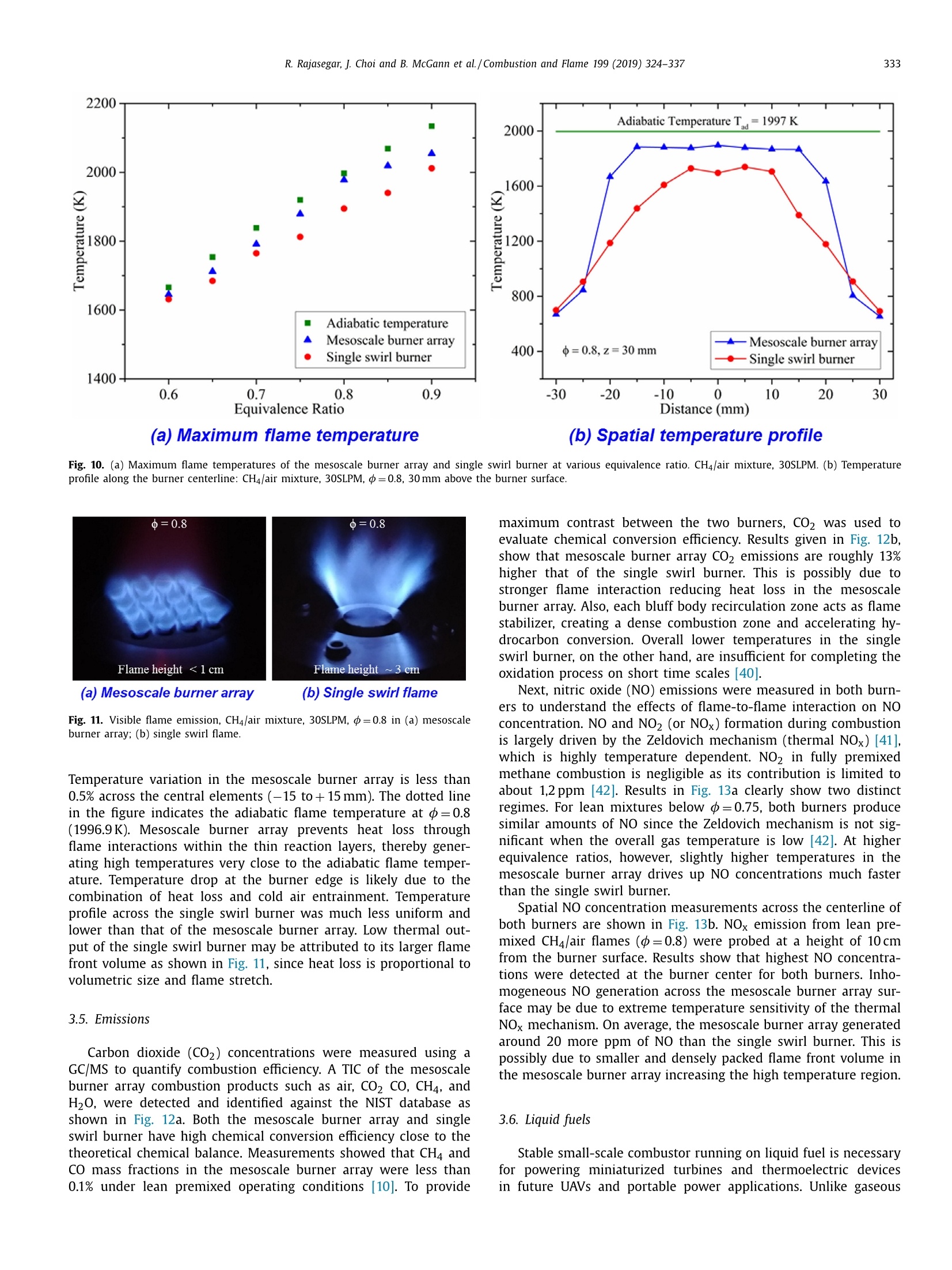
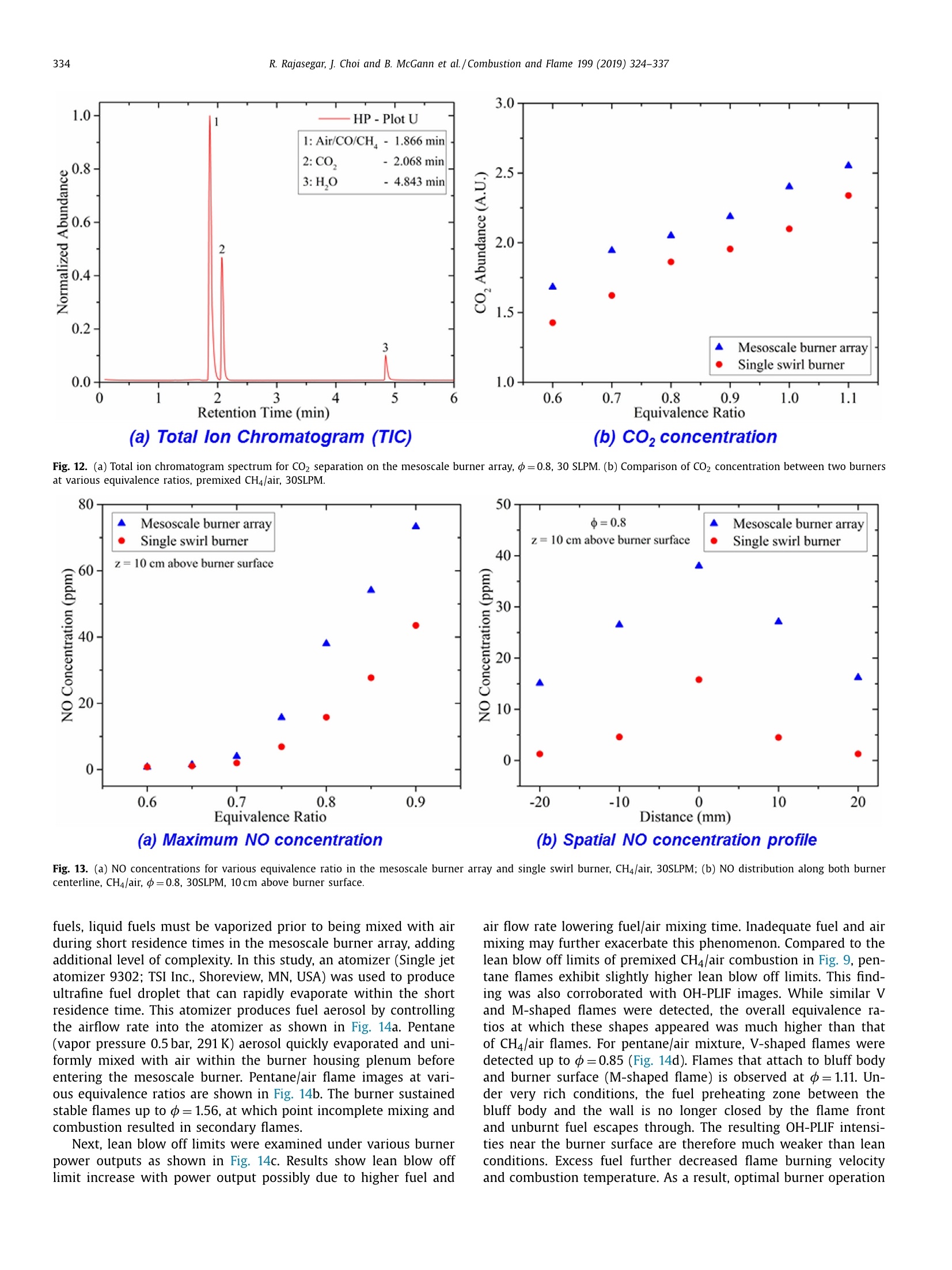
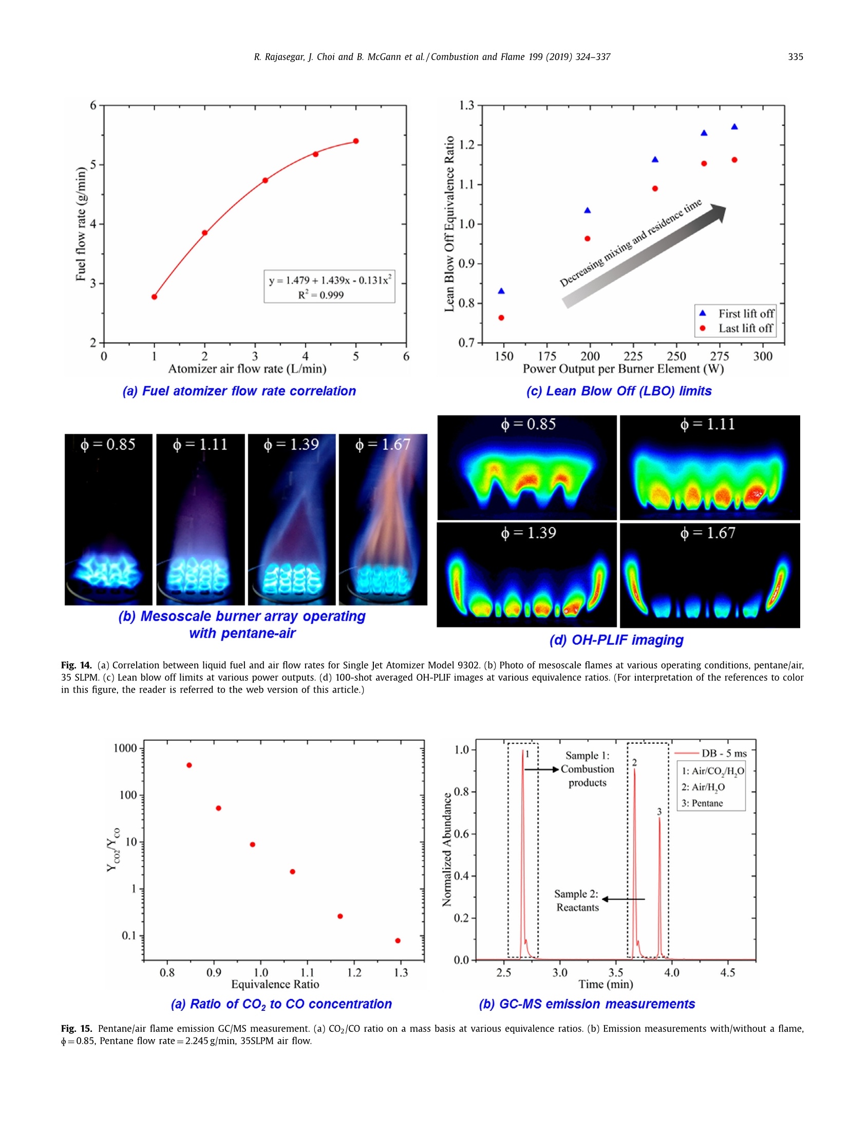
方案详情

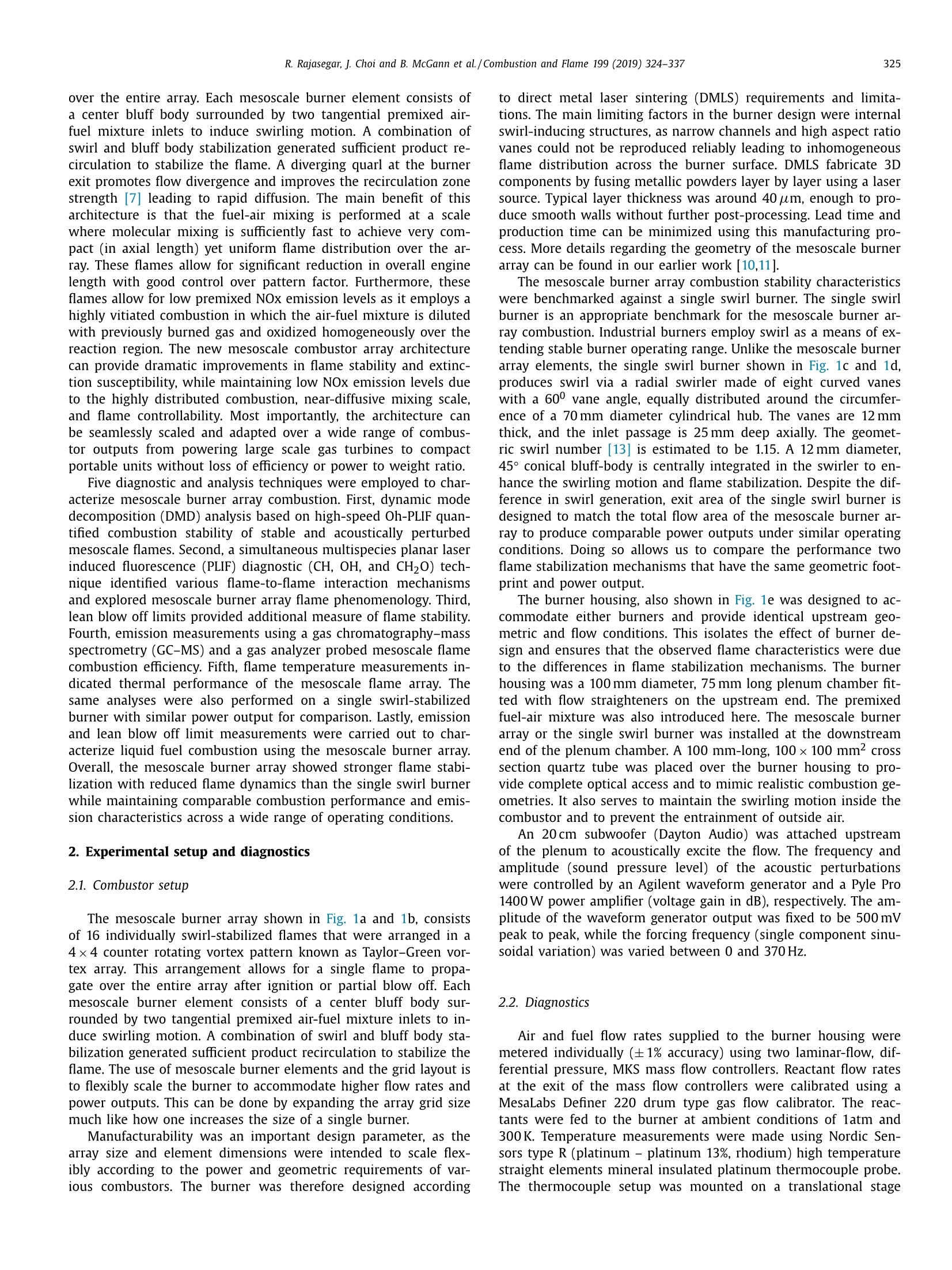
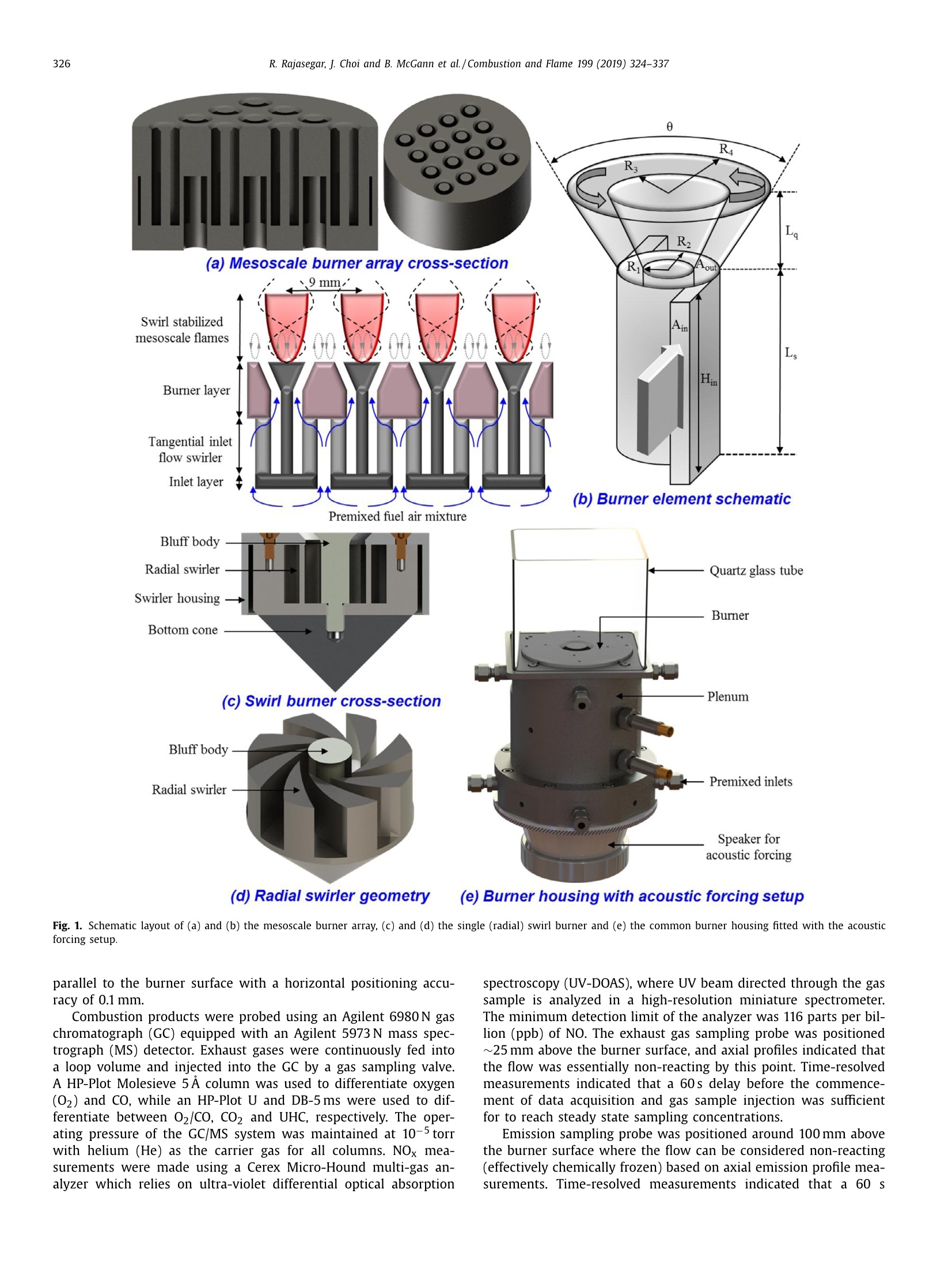
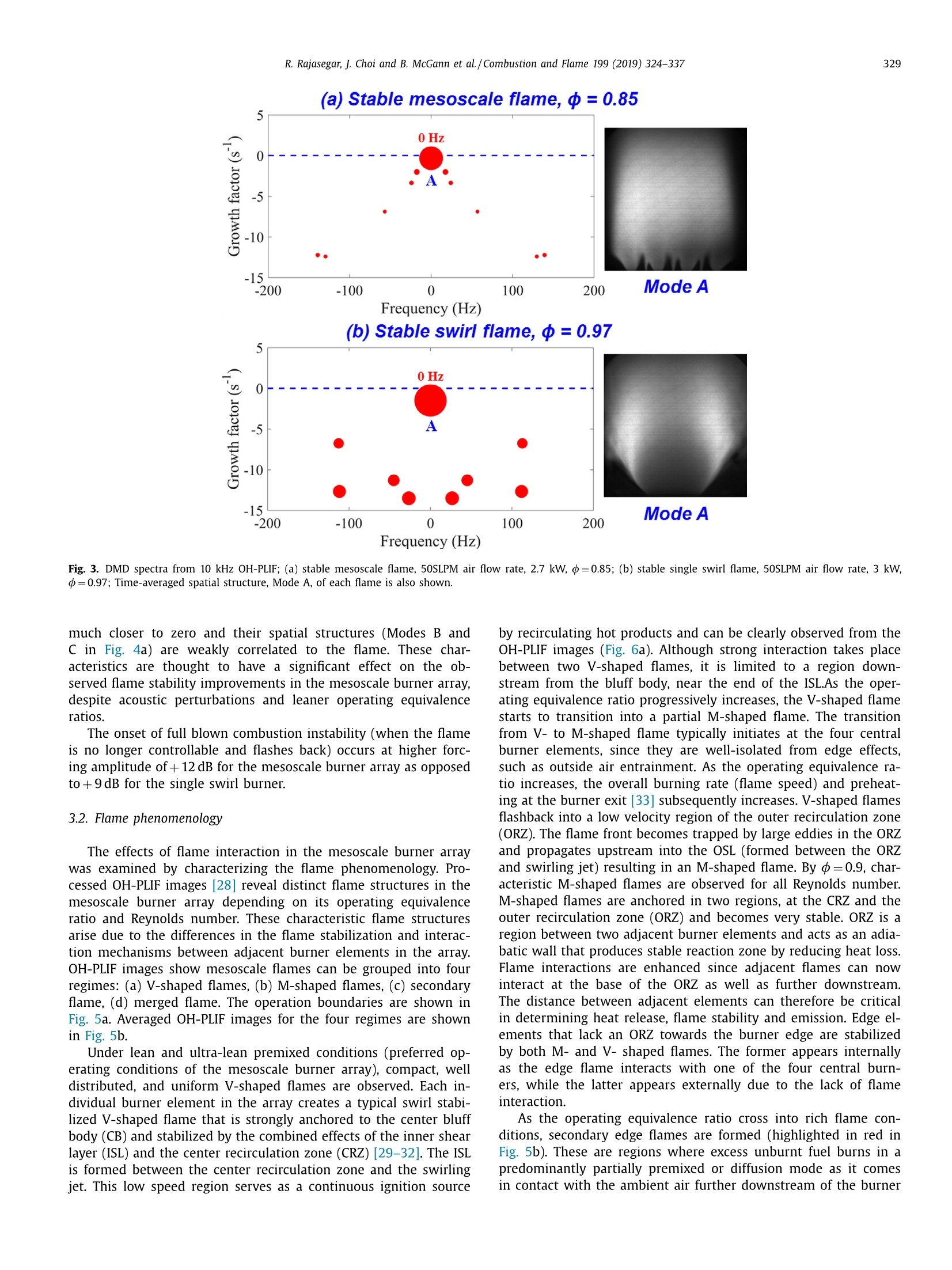
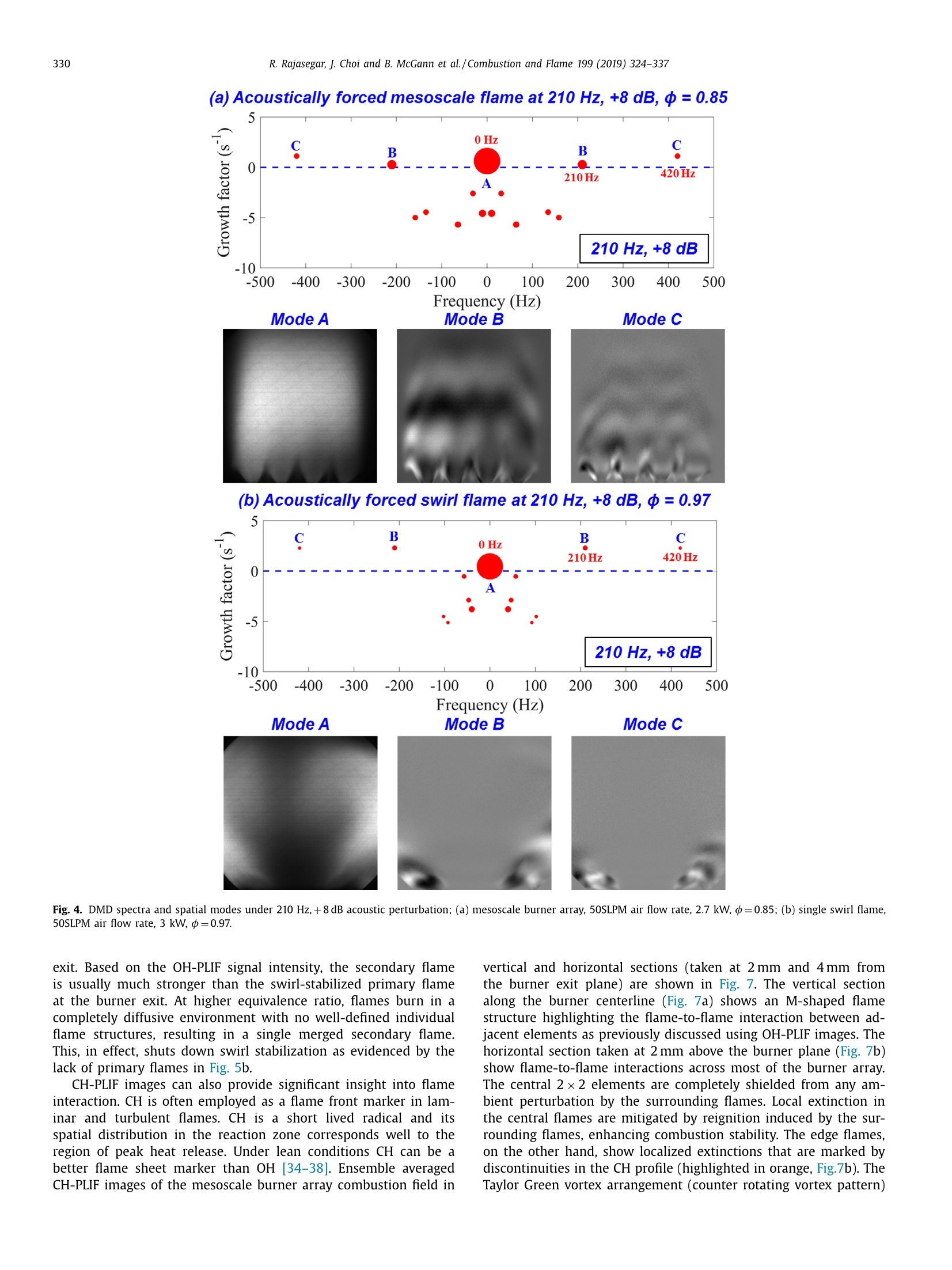
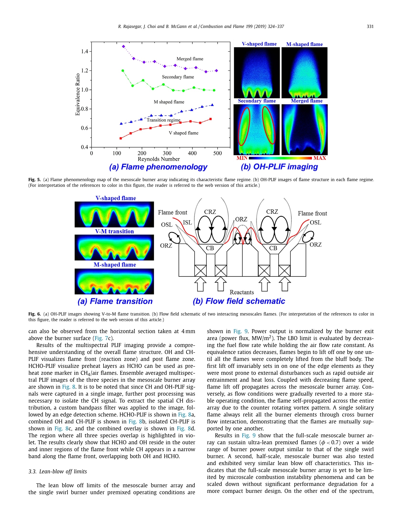
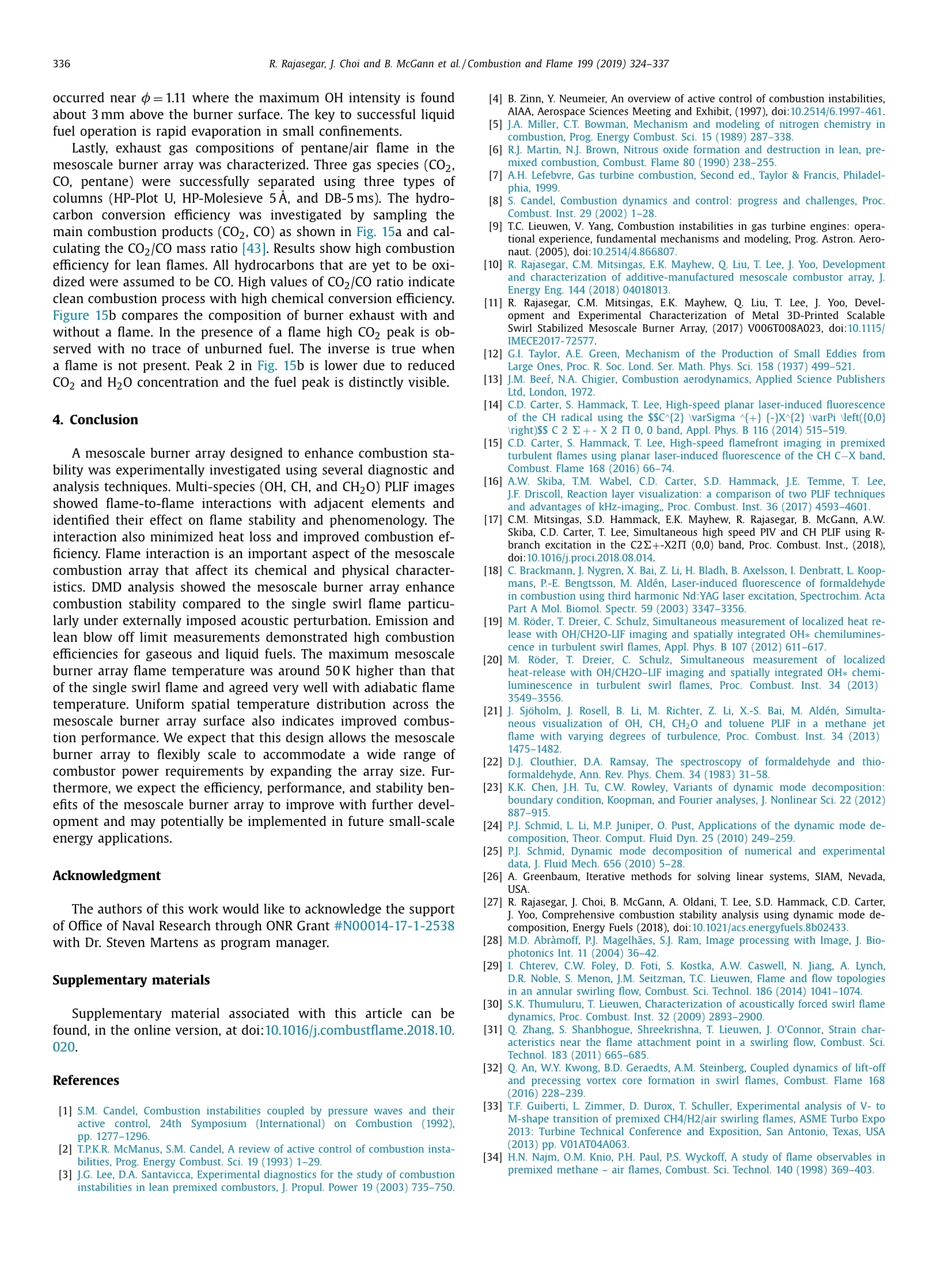
Combustion and Flame 199 (2019) 324-337 325R. Rajasegar, J. Choi and B. McGann et al./Combustion and Flame 199 (2019) 324-337 https://doi.org/10.1016/j.combustflame.2018.10.0200010-2180/Published by Elsevier Inc. on behalf of The Combustion Institute. Contents lists available at ScienceDirect Combustion and Flame ELSEVIER journal homepage: www.elsevier.com/locate/combustflame Mesoscale burner array performance analysis Rajavasanth Rajasegar, Jeongan Choi, Brendan McGann, Anna Oldani, Tonghun Leed*,Stephen D. Hammack, Campbell D. Carter, Jihyung Yooc a University of Illinois at Urbana-Champaign, Urbana, IL 61801, USA D U.S. Air Force Research Laboratory, Wright-Patterson Air Force Base, OH 45433, USA Hanyang University, Seoul 04763, South Korea ARTICLE INFO A BSTRACT Article history:Received 4 July 2018Revised 16 October 2018Accepted 16 October 2018Available online 7 November 2018 Keywords:Combustion instabilitySwirl stabilizationLean blow off limitsHigh-speed PLIFAcoustic perturbationDynamic mode decomposition Combustion characteristics of a mesoscale burner array have been studied using several diagnostic andanalysis techniques. The array was specifically configured to enhance overall combustion stability, partic-ularly under lean operating conditions, by promoting flame to flame interactions between neighboringelements. The 4×4 burner array demonstrated stable operations up to 3kW and is designed to flexiblyaccommodate wide range of combustion power outputs by scaling the element dimensions or array size.Flame stabilizing mechanisms were experimentally examined using OH, CH, and CH20 planar laser in-duced fluorescence (PLIF) of premixed CH4 and air flames at operating equivalence ratios between 0.7and 1.2. A quantitative measure of flame stability was obtained through dynamic mode decomposition(DMD) analysis of high speed OH-PLIF images. Lean blow off limits and emissions were also character-ized across a wider range of equivalence ratios to better understand mesoscale burner array combustioncharacteristics. Lastly,combustion experiments using liquid fuel, pentane (CsH12), were also carried out.Marked improvement in combustion stability was observed compared to a single swirl-stabilized flameof similar power output. Results indicate mesoscale burner arrays can potentially serve as flexible andscalable next generation propulsion and power generation systems. 1. Introduction In the recent years, improving the efficiency of gas-turbineengines while complying with the stringent emission regulationshas become a significant challenge. Furthermore, combustion in-stabilities are a major problem in the design of modern high-performance propulsion systems [1]. They often manifest as largeamplitude pressure oscillations that result in many undesirable ef-fects leading to performance degradation [2]. Combustion instabil-ities refer to self-sustained combustion oscillations at or near theacoustic frequency of the combustion chamber, which arise dueto the closed-loop coupling between unsteady heat release andpressure fluctuations [3,4]. These phenomena can induce unsta-ble operations where enhanced heat transfer at combustor wallsmay lead to partial or total blow off [1-4]. Furthermore, the typi-cal low frequency oscillations induce large mechanical vibrations inthe system that may ultimately result in combustor failure. Com-bustion instability is a major concern for modern gas turbines thatare being designed to operate under increasingly ultra-lean condi- ( * Corresponding a uthor. ) ( E-mail a ddress: t onghun@illino i s.edu ( T . L e e). ) tions. These operating modes result in significant reduction in NOxemissions and maintenance cost due to lower flame temperatures[5,6] leading to increased component life time [7]. However, re-duced turbine inlet temperatures can lead to combustion instabili-ties in addition to lowering the efficiency and specific work out-put. Even small perturbations in lean premixed combustion cantrigger strong combustion instabilities [8,9] that exacerbate leanblow out susceptibility. Thus, the potential harm to system perfor-mance posed by combustion instabilities, often necessitates flameoscillation mitigation during the development of a new combus-tion system. However, modifications to existing combustor designmay not satisfactorily fulfill both design requirements. Hence, a dif-ferent combustion architecture may be necessary to alleviate theabove noted tradeoff. This paper utilizes highly distributed, millimeter-scale combus-tion arranged in a grid array to improve combustion stability. Amesoscale combustor array [10,11] featuring 16 interacting swirl-stabilized burner elements arranged in a 4×4 counter rotating vor-tex pattern known as Taylor-Green vortex array [12] was built forthis study. Individual burner elements support nearby elements viaflame-to-flame interaction. Despite overall smaller flame size, thisconfiguration allows a more stable flame characteristics. A singleremaining flame after ignition or partial blow off can propagate over the entire array. Each mesoscale burner element consists ofa center bluff body surrounded by two tangential premixed air-fuel mixture inlets to induce swirling motion. A combination ofswirl and bluff body stabilization generated sufficient product re-circulation to stabilize the flame. A diverging quarl at the burnerexit promotes flow divergence and improves the recirculation zonestrength [7] leading to rapid diffusion. The main benefit of thisarchitecture is that the fuel-air mixing is performed at a scalewhere molecular mixing is sufficiently fast to achieve very com-pact (in axial length) yet uniform flame distribution over the ar-ray. These flames allow for significant reduction in overall enginelength with good control over pattern factor. Furthermore, theseflames allow for low premixed NOx emission levels as it employs ahighly vitiated combustion in which the air-fuel mixture is dilutedwith previously burned gas and oxidized homogeneously over thereaction region. The new mesoscale combustor array architecturecan provide dramatic improvements in flame stability and extinc-tion susceptibility, while maintaining low NOx emission levels dueto the highly distributed combustion, near-diffusive mixing scale,and flame controllability. Most importantly, the architecture canbe seamlessly scaled and adapted over a wide range of combus-tor outputs from powering large scale gas turbines to compactportable units without loss of efficiency or power to weight ratio. Five diagnostic and analysis techniques were employed to char-acterize mesoscale burner array combustion. First, dynamic modedecomposition (DMD) analysis based on high-speed Oh-PLIF quan-tified combustion stability of stable and acoustically perturbedmesoscale flames. Second, a simultaneous multispecies planar laserinduced fluorescence (PLIF) diagnostic (CH, OH, and CH20) tech-nique identified various flame-to-flame interaction mechanismsand explored mesoscale burner array flame phenomenology. Third,lean blow off limits provided additional measure of flame stability.Fourth, emission measurements using a gas chromatography-massspectrometry (GC-MS) and a gas analyzer probed mesoscale flamecombustion efficiency. Fifth, flame temperature measurements in-dicated thermal performance of the mesoscale flame array. Thesame analyses were also performed on a single swirl-stabilizedburner with similar power output for comparison. Lastly, emissionand lean blow off limit measurements were carried out to char-acterize liquid fuel combustion using the mesoscale burner array.Overall, the mesoscale burner array showed stronger flame stabi-lization with reduced flame dynamics than the single swirl burnerwhile maintaining comparable combustion performance and emis-sion characteristics across a wide range of operating conditions. 2. Experimental setup and diagnostics 2.1. Combustor setup The mesoscale burner array shown in Fig. 1a and 1b, consistsof 16 individually swirl-stabilized flames that were arranged in a4×4 counter rotating vortex pattern known as Taylor-Green vor-tex array. This arrangement allows for a single flame to propa-gate over the entire array after ignition or partial blow off. Eachmesoscale burner element consists of a center bluff body sur-rounded by two tangential premixed air-fuel mixture inlets to in-duce swirling motion. A combination of swirl and bluff body sta-bilization generated sufficient product recirculation to stabilize theflame. The use of mesoscale burner elements and the grid layout isto flexibly scale the burner to accommodate higher flow rates andpower outputs. This can be done by expanding the array grid sizemuch like how one increases the size of a single burner. Manufacturability was an important design parameter, as thearray size and element dimensions were intended to scale flex-ibly according to the power and geometric requirements of var-ious combustors. The burner was therefore designed according to direct metal laser sintering (DMLS) requirements and limita-tions. The main limiting factors in the burner design were internalswirl-inducing structures, as narrow channels and high aspect ratiovanes could not be reproduced reliably leading to inhomogeneousflame distribution across the burner surface. DMLS fabricate 3Dcomponents by fusing metallic powders layer by layer using a lasersource. Typical layer thickness was around 40 um, enough to pro-duce smooth walls without further post-processing. Lead time andproduction time can be minimized using this manufacturing pro-cess. More details regarding the geometry of the mesoscale burnerarray can be found in our earlier work [10,11]. The mesoscale burner array combustion stability characteristicswere benchmarked against a single swirl burner. The single swirlburner is an appropriate benchmark for the mesoscale burner ar-ray combustion. Industrial burners employ swirl as a means of ex-tending stable burner operating range. Unlike the mesoscale burnerarray elements, the single swirl burner shown in Fig. 1c and 1d,produces swirl via a radial swirler made of eight curved vaneswith a 60° vane angle, equally distributed around the circumfer-ence of a 70mm diameter cylindrical hub. The vanes are 12 mmthick, and the inlet passage is 25 mm deep axially. The geomet-ric swirl number [13] is estimated to be 1.15. A 12 mm diameter,45° conical bluff-body is centrally integrated in the swirler to en-hance the swirling motion and flame stabilization. Despite the dif-ference in swirl generation, exit area of the single swirl burner isdesigned to match the total flow area of the mesoscale burner ar-ray to produce comparable power outputs under similar operatingconditions. Doing so allows us to compare the performance twoflame stabilization mechanisms that have the same geometric foot-print and power output. The burner housing, also shown in Fig. 1e was designed to ac-commodate either burners and provide identical upstream geo-metric and flow conditions. This isolates the effect of burner de-sign and ensures that the observed flame characteristics were dueto the differences in flame stabilization mechanisms. The burnerhousing was a 100 mm diameter, 75 mm long plenum chamber fit-ted with flow straighteners on the upstream end. The premixedfuel-air mixture was also introduced here. The mesoscale burnerarray or the single swirl burner was installed at the downstreamend of the plenum chamber. A 100 mm-long, 100×100 mm² crosssection quartz tube was placed over the burner housing to pro-vide complete optical access and to mimic realistic combustion ge.ometries. It also serves to maintain the swirling motion inside thecombustor and to prevent the entrainment of outside air. An 20cm subwoofer (Dayton Audio) was attached upstreamof the plenum to acoustically excite the flow. The frequency andamplitude (sound pressure level) of the acoustic perturbationswere controlled by an Agilent waveform generator and a Pyle Pro1400 W power amplifier (voltage gain in dB), respectively. The am-plitude of the waveform generator output was fixed to be 500 mVpeak to peak, while the forcing frequency (single component sinu-soidal variation) was varied between 0 and 370 Hz. 2.2. Diagnostics Air and fuel flow rates supplied to the burner housing weremetered individually (±1% accuracy) using two laminar-flow, dif-ferential pressure, MKS mass flow controllers. Reactant flow ratesat the exit of the mass flow controllers were calibrated using aMesaLabs Definer 220 drum type gas flow calibrator. The reac-tants were fed to the burner at ambient conditions of 1atm and300K. Temperature measurements were made using Nordic Sen-sors type R (platinum - platinum 13%, rhodium) high temperaturestraight elements mineral insulated platinum thermocouple probe.The thermocouple setup was mounted on a translational stage (d) Radial swirler geometry (e) Burner housing with acoustic forcing setup Fig. 1. Schematic layout of (a) and (b) the mesoscale burner array, (c) and (d) the single (radial) swirl burner and (e) the common burner housing fitted with the acousticforcing setup. parallel to the burner surface with a horizontal positioning accu-racy of 0.1 mm. Combustion products were probed using an Agilent 6980 N gaschromatograph (GC) equipped with an Agilent 5973N mass spec-trograph (MS) detector. Exhaust gases were continuously fed intoa loop volume and injected into the GC by a gas sampling valve.A HP-Plot Molesieve 5A column was used to differentiate oxygen(02) and CO, while an HP-Plot U and DB-5 ms were used to dif-ferentiate between 02/CO, CO2 and UHC, respectively. The oper-ating pressure of the GC/MS system was maintained at 10-5 torrwith helium (He) as the carrier gas for all columns. NOx mea-surements were made using a Cerex Micro-Hound multi-gas an-alyzer which relies on ultra-violet differential optical absorption spectroscopy (UV-DOAS), where UV beam directed through the gassample is analyzed in a high-resolution miniature spectrometer.The minimum detection limit of the analyzer was 116 parts per bil-lion(ppb) of NO. The exhaust gas sampling probe was positioned~25 mm above the burner surface, and axial profiles indicated thatthe flow was essentially non-reacting by this point. Time-resolvedmeasurements indicated that a 60s delay before the commence-ment of data acquisition and gas sample injection was sufficientfor to reach steady state sampling concentrations. Emission sampling probe was positioned around 100 mm abovethe burner surface where the flow can be considered non-reacting(effectively chemically frozen) based on axial emission profile mea-surements. Time-resolved measurements indicated that a 60 s M-Mirror;L-Lens; BC-Beam Combiner; BS-Beam Sampler; PMT -Photo Multiplier Tube delay between gas sample injection and data acquisition was suf-ficient to reach steady state sampling concentrations. Gas specieswere identified by comparing mass spectra against the NISTdatabase. Mass fractions of each species present were determinedby integrating peaks from the total ion chromatogram (TIC). NOconcentrations were determined using a dedicated sensor that uti-lizes a least-squares regression analysis and Beer-Lamberts law. 2.3. Laser diagnostics setup A schematic of the simultaneous multispectral (HCHO/CH/OH)PLIF imaging setup is shown in Fig. 2. The CH/OH planar laserinduced fluorescence (CH/OH-PLIF) system used the second har-monic output of a Spectra Physics Quanta Ray, Nd: YAG laser(532 nm, 500mJ/pulse) operating at 10Hz to pump a Sirah Pre-cision Scan dye laser containing DCM dye dissolved in ethanol.The red dye laser beam was then frequency-doubled using anintegral B-barium-borate doubling crystal. The dye laser output(12 mJ/pulse, 0.1 cm-1 spectral line width at 310nm) was thenprecisely tuned to excite specific transitions based on the targetedspecies (CH, OH, or combined CH-OH) as listed in Table 1. A ju-dicious choice of excitation transitions and filtering schemes arerequired to isolate the PLIF signal of interest using a single laser and camera configuration [14-17] due to the overlap between theC-X (0,0) band of CH and the A-X(0,0) band of OH near 310 nm.The laser pulse energy was monitored using a fast photodiode andan oscilloscope. The final laser beam was formed into a 50 mm-high, 0.3 mm-thick (FWHM) sheet in the probe region using atwo-lens telescope. Fluorescence was isolated from backgroundscattering and visible flame emission using two custom SemrockAFRL-0002 long-wave-pass filters and a Schott UG-5 filter. Fluores-cence collected at right angle (perpendicular to the laser sheet) us-ing a 100 mm focal length, f/2.8 Sodern Cerco UV lens was focusedonto a 1280×1024 pixel Andor iStar intensified (gate=100 ns) CCDcamera at 10 Hz. The CH20 (formaldehyde) PLIF system used the third harmonicoutput of a Spectra Physics Quanta Ray, Nd: YAG laser (355nm,150 mJ/pulse) operating at 10 Hz. The 355 nm laser beam can ex-cite multiple rotational levels within a vibrational band of HCHO[18-22]. For simultaneous multispectral PLIF imaging, the 355 nmlaser beam (HCHO-PLIF) and 310 nm laser beam (CH/OH-PLIF) wascombined using a beam combiner (a short pass dielectric mirrorwhich reflects 355 nm beam while allowing the 310nm beam topass through). Output beams are then expanded out into 50 mm-high, 0.3 mm-thick (FWHM) sheets in the probe region using thesame set of sheet forming optics. One of the two beam is delayed Table 1Targeted transitions and corresponding excitation wavelengths for select species in multispectralPLIF imaging. Species Transition Wavelength (nm) OH Q(12) line of A2+-X2II (0,0) band 310.60 CH Ri(13)+R2(13) line of C22+→X²II (0,0) band 310.69 Combined CH-OH OH:Q(15) line of A2Z+→X²II (0,0) band 311.96 CH20 CH: R1(8)+R2(8) line of C2+→XII (0,0) band Multiple rotational lines of A1A2→X1A 4} band 355 by 250 ns to prevent cross talk between resulting fluorescence.Broadband CH20 fluorescence in the range of 375 to 425 nm wasisolated from background scattering and flame emissions using anEdmund Optics high transmission band pass filter (50 nm FWHMat 400nm). Fluorescence collected at right angle using a 100 mmfocal length, f/2.8 Sodern Cerco UV lens was focused onto a 10 Hz,1280×1024-pixel LaVision Imager Intense CCD camera coupled toa LaVision IRO image intensifier (gate=100 ns). A 10 kHz OH-PLIF system used a similar layout, but with differ-ent lasers and camera. A diode pumped solid state (DPSS), Edge-Wave Innoslab IS12II-E, Nd:YAG laser, with a maximum outputpower of 60 W, at 532 nm (second harmonic) pumped a tunableSirah CREDO dye laser containing DCM dye dissolved in ethanol.The red dye laser beam was then frequency doubled using thesame technique as the CH-OH PLIF system. The final output pulseenergy was roughly 0.2 mJ/pulse with a 0.1 cm-1 spectral linewidth at 310.60 nm. The UV laser beam was formed into a 120 um-thick sheet (FWHM) in the probe region using a 25 mm plano-concave cylindrical lens and a 750 mm spherical plano-convex lens(two-lens telescope). Fluorescence was isolated from backgroundscattering and visible flame emission using two custom SemrockAFRL-0002 long-wave-pass filters and a Schott UG-5 filter. Fluo-rescence signal collected at right angle (perpendicular to the lasersheet) using a 100 mm focal length, f/2.8 Sodern Cerco UV lens wasfocused onto the 896×848-pixel imaging array of a high speedPhotron SA-Z CMOS camera coupled to a Lambert HI-CATT two-stage image intensifier. 3. Results and discussions 3.1. Flame dynamics using dynamic mode decomposition (DMD) Coherent structures and their frequency response are analyzedthrough dynamic mode decomposition by constructing a lower-dimension companion matrix from a series of images which forma Krylov sequence under linear-tangent approximation. The eigen-values and eigenvectors of this newly constructed matrix approx-imate those of a nonlinear higher dimension system matrix gov-erning the combustion phenomena [23]. A detailed and rigorousmathematical description can be found in [24,25] and only a briefdescription will be given here. Letting u represent data from a sin-gle experimental image, an image sequence can be defined as aKrylov sequence, VN={V1,V2,.....,DN}[26] under linear-tangentapproximation. For sufficiently large sequence, the images becomelinearly dependent, leading to the following formulation: where s is the last column of the companion matrix A and r isthe residual vector. Solving for the least-square solution of A, itseigenvalues (empirical Ritz values) and eigenvectors are then usedto approximate coherent structures of the given reactive flow field. DMD is a robust and powerful analysis technique that can ex-tract coherent structures and identify prevalent frequencies fromexperimental datasets in the absence of an underlying model, evenin the presence of experimental uncertainties, measurement errors or environmental noise [24,25]. Details regarding the validation ofDMD using snapshots of synthetic numeric functions and its ap-plication to combustion phenomenon using laminar flame OH-PLIFimages have been discussed at length in our previous work [27]. Inour previous effort [27], DMD analysis carried out on high-speedOH-PLIF images of acoustically-perturbed swirl-stabilized flamesshowed that DMD is an effective analysis technique for charac-terizing and quantifying flame stability, as it could accurately re-solve dominant spatial structures present in the recirculation zoneor shear layer along with their corresponding growth rates and en-ergy contents at various perturbation frequencies and amplitudes. 2000 images of 10kHz OH-PLIF data were used for all sub-sequent DMD analyses. 10 kHz OH-PLIF images allow for reliableDMD analysis of frequencies up to 5 kHz (Nyquist criterion), whichis more than enough to determine the effects of acoustic forcingin this study. Initial flame stability analyses were performed un-der stable (non-excited) mesoscale burner array and single swirlburner condition. DMD spectra of the two stable flames areshown in Fig. 3. Only the most relevant modes are shown in thefigure. The marker size is proportional to a measure of coher-ence for the given mode (energy content of the spatial mode) andhelp rank the relevant structures over noise-contaminated ones.As expected, the mode with the highest energy content and themost stable growth factor (closest to 0) is located at the meanfrequency (0Hz, denoted by A in Fig. 3). The corresponding spa-tial structure, Mode A in the figure, represents the time-averagedflame position. The mesoscale burner array (中=0.85) exhibits avery stable M-shaped flame. Energy contribution from fluctuatingmodes (non-zero frequencies) are minimal.The single swirl burner(=0.97) exhibits a flame anchored in the recirculation zone withdiscernible oscillations in the outer shear layer (OSL), as governedby modes between 20 and 110 Hz in its DMD spectrum. Relativelylarge negative growth factors associated with these modes indi-cate mostly stable flame, but larger marker size indicate fluctuatingmodes contribute more energy compared to the mesoscale burnerarray. The same comparison was performed under externally imposedacoustic excitation to characterize the stabilization effect of themesoscale burner array. The speaker attached to the burner hous-ing was driven at several low audible frequencies up to 370Hzand various amplitudes from+3 to+8dB (power amplifier volt-age gain) for both burners. Figure 4 shows DMD spectra un-der 210Hz,+8 dB acoustic perturbation. The time-averaged spa-tial structure of the mesoscale burner array (mode A, Fig. 4a)shows a V-shaped flame structure. Mode A of the single swirlburner (Fig. 4b), on the other hand, is spread outwards due tothe extremely oscillatory behavior of the flame. DMD analysis ofboth flames assign positive growth rates for three relevant modes(mean, resonant, and first harmonic frequencies). Growth factors ofthe single swirl flames at its resonant and first harmonic frequen-cies are relatively high. Furthermore, spatial structures (oscillatorybehaviors) at these frequencies (Modes B and C in Fig. 4b), aremostly concentrated in the recirculation zone thereby exacerbat-ingoscillatory behaviors (Fig. 4b). Growth factors of the mesoscaleburner array at its resonant and first harmonic frequencies are (a) Stable mesoscale flame, 中 = 0.85 Frequency (Hz)(b)Stable swirl flame, 中=0.970 Hz Mode A much closer to zero and their spatial structures (Modes B andC in Fig. 4a) are weakly correlated to the flame. These char-acteristics are thought to have a significant effect on the ob-served flame stability improvements in the mesoscale burner array,despite acoustic perturbations and leaner operating equivalenceratios. The onset of full blown combustion instability (when the flameis no longer controllable and flashes back) occurs at higher forc-ing amplitude of+ 12 dB for the mesoscale burner array as opposedto+9dB for the single swirl burner. 3.2. Flame phenomenology The effects of flame interaction in the mesoscale burner arraywas examined by characterizing the flame phenomenology. Pro-cessed OH-PLIF images [28]reveal distinct flame structures in themesoscale burner array depending on its operating equivalenceratio and Reynolds number. These characteristic flame structuresarise due to the differences in the flame stabilization and interac-tion mechanisms between adjacent burner elements in the array.OH-PLIF images show mesoscale flames can be grouped into fourregimes: (a) V-shaped flames, (b) M-shaped flames, (c) secondaryflame, (d) merged flame. The operation boundaries are shown inFig. 5a. Averaged OH-PLIF images for the four regimes are shownin Fig. 5b. Under lean and ultra-lean premixed conditions (preferred op-erating conditions of the mesoscale burner array), compact, welldistributed, and uniform V-shaped flames are observed. Each in-dividual burner element in the array creates a typical swirl stabi-lized V-shaped flame that is strongly anchored to the center bluffbody (CB) and stabilized by the combined effects of the inner shearlayer (ISL) and the center recirculation zone (CRZ) [29-32].The ISLis formed between the center recirculation zone and the swirlingjet. This low speed region serves as a continuous ignition source by recirculating hot products and can be clearly observed from theOH-PLIF images (Fig. 6a). Although strong interaction takes placebetween two V-shaped flames, it is limited to a region down-stream from the bluff body, near the end of the ISL.As the oper-ating equivalence ratio progressively increases, the V-shaped flamestarts to transition into a partial M-shaped flame. The transitionfrom V-to M-shaped flame typically initiates at the four centralburner elements, since they are well-isolated from edge effects,such as outside air entrainment. As the operating equivalence ra-tio increases, the overall burning rate (flame speed) and preheat-ing at the burner exit [33] subsequently increases. V-shaped flamesflashback into a low velocity region of the outer recirculation zone(ORZ). The flame front becomes trapped by large eddies in the ORZand propagates upstream into the OSL (formed between the ORZand swirling jet) resulting in an M-shaped flame. By d=0.9, characteristic M-shaped flames are observed for all Reynolds number.M-shaped flames are anchored in two regions, at the CRZ and theouter recirculation zone (ORZ) and becomes very stable. ORZ is aregion between two adjacent burner elements and acts as an adia-batic wall that produces stable reaction zone by reducing heat loss.Flame interactions are enhanced since adjacent flames can nowinteract at the base of the ORZ as well as further downstream.The distance between adjacent elements can therefore be criticalin determining heat release, flame stability and emission.Edge el-ements that lack an ORZ towards the burner edge are stabilizedby both M and V- shaped flames. The former appears internallyas the edge flame interacts with one of the four central burn-ers, while the latter appears externally due to the lack of flameinteraction. As the operating equivalence ratio cross into rich flame con-ditions, secondary edge flames are formed (highlighted in red inFig.5b). These are regions where excess unburnt fuel burns in apredominantly partially premixed or diffusion mode as it comesin contact with the ambient air further downstream of the burner (a) Acoustically forced mesoscale flame at 210 Hz, +8 dB, 中=0.85 Mode A Mode B Mode C (b) Acoustically forced swirl flame at 210 Hz, +8 dB, 中 =0.97 Mode A Mode B Mode C Fig. 4. DMD spectra and spatial modes under 210 Hz,+8 dB acoustic perturbation; (a) mesoscale burner array, 50SLPM air flow rate, 2.7 kW,中=0.85; (b) single swirl flame,50SLPM air flow rate, 3 kW,中=0.97. exit. Based on the OH-PLIF signal intensity, the secondary flameis usually much stronger than the swirl-stabilized primary flameat the burner exit. At higher equivalence ratio, flames burn in acompletely diffusive environment with no well-defined individualflame structures, resulting in a single merged secondary flame.This, in effect, shuts down swirl stabilization as evidenced by thelack of primary flames in Fig. 5b. CH-PLIF images can also provide significant insight into flameinteraction. CH is often employed as a flame front marker in lam-inar and turbulent flames. CH is a short lived radical and itsspatial distribution in the reaction zone corresponds well to theregion of peak heat release. Under lean conditions CH can be abetter flame sheet marker than OH [34-38]. Ensemble averagedCH-PLIF images of the mesoscale burner array combustion field in vertical and horizontal sections (taken at 2 mm and 4mm fromthe burner exit plane) are shown in Fig.7. The vertical sectionalong the burner centerline (Fig. 7a) shows an M-shaped flamestructure highlighting the flame-to-flame interaction between ad-jacent elements as previously discussed using OH-PLIF images. Thehorizontal section taken at 2 mm above the burner plane (Fig. 7b)show flame-to-flame interactions across most of the burner array.The central 2×2 elements are completely shielded from any am-bient perturbation by the surrounding flames. Local extinction inthe central flames are mitigated by reignition induced by the sur-rounding flames, enhancing combustion stability. The edge flames,on the other hand, show localized extinctions that are marked bydiscontinuities in the CH profile (highlighted in orange, Fig.7b). TheTaylor Green vortex arrangement (counter rotating vortex pattern) (a) Flame phenomenology Fig.5. (a) Flame phenomenology map of the mesoscale burner array indicating its characteristic flame regime. (b) OH-PLIF images of flame structure in each flame regime.(For interpretation of the references to color in this figure, the reader is referred to the web version of this article.) Fig. 6. (a) OH-PLIF images showing V-to-M flame transition. (b) Flow field schematic of two interacting mesoscales flames. (For interpretation of the references to color inthis figure, the reader is referred to the web version of this article.) can also be observed from the horizontal section taken at 4 mmabove the burner surface (Fig.7c). Results of the multispectral PLIF imaging provide a compre-hensive understanding of the overall flame structure. OH and CH-PLIF visualizes flame front (reaction zone) and post flame zone.HCHO-PLIF visualize preheat layers as HCHO can be used as pre-heat zone marker in CH4/air flames. Ensemble averaged multispec-tral PLIF images of the three species in the mesoscale burner arrayare shown in Fig. 8. It is to be noted that since CH and OH-PLIF sig-nals were captured in a single image, further post processing wasnecessary to isolate the CH signal. To extract the spatial CH dis-tribution, a custom bandpass filter was applied to the image, fol-lowed by an edge detection scheme. HCHO-PLIF is shown in Fig. 8a,combined OH and CH-PLIF is shown in Fig.8b, isolated CH-PLIF isshown in Fig. 8c, and the combined overlay is shown in Fig. 8d.The region where all three species overlap is highlighted in vio-let. The results clearly show that HCHO and OH reside in the outerand inner regions of the flame front while CH appears in a narrowband along the flame front, overlapping both OH and HCHO. 3.3. Lean-blow off limits The lean blow off limits of the mesoscale burner array andthe single swirl burner under premixed operating conditions are shown in Fig.9. Power output is normalized by the burner exitarea (power flux, MW/m). The LBO limit is evaluated by decreas-ing the fuel flow rate while holding the air flow rate constant. Asequivalence ratios decreases, flames begin to lift off one by one un-til all the flames were completely lifted from the bluff body. Thefirst lift off invariably sets in on one of the edge elements as theywere most prone to external disturbances such as rapid outside airentrainment and heat loss. Coupled with decreasing flame speed,flame lift off propagates across the mesoscale burner array. Con-versely, as flow conditions were gradually reverted to a more sta-ble operating condition,the flame self-propagated across the entirearray due to the counter rotating vortex pattern. A single solitaryflame always relit all the burner elements through cross burnerflow interaction, demonstrating that the flames are mutually sup-ported by one another. Results in Fig. 9 show that the full-scale mesoscale burner ar-ray can sustain ultra-lean premixed flames (中<0.7) over a widerange of burner power output similar to that of the single swirlburner. A second, half-scale, mesoscale burner was also testedand exhibited very similar lean blow off characteristics. This in-dicates that the full-scale mesoscale burner array is yet to be lim-ited by microscale combustion instability phenomena and can bescaled down without significant performance degradation for amore compact burner design. On the other end of the spectrum, (a) Vertical section 4mm 2mm1. 燃... (b) Horizontal section (2 mm) (c) Horizontal section (4mm) Central (2x2) flames isolated from edge effects Local extinction in edgeflames due to heat loss andentrainment Taylor green vortexarrangement Fig. 8. Simultaneous multispectral PLIF (HCHO, CH and OH) of mesoscale burner:(a) HCHO, (b) CH/OH, (c) isolated CH, (d) overlaid image. The spatial overlap re-gion between the three species is highlighted in violet. (For interpretation of thereferences to color in this figure, the reader is referred to the web version of thisarticle.) higher power output can easily be obtained by adding more el-ements to the existing mesoscale architecture. This in effect willenable a more stable flame as the ratio of central and edge burnerelements increases. 3.4. Flame temperature Two temperature measurements were made to evaluate thethermal performance of the two burners. First, maximum temper-atures at the flame surface under various lean equivalence ratio isshown in Fig. 10a. All temperature measurements were corrected Fig. 9. Lean blow off limits for two mesoscale burners and a single swirl burner atvarious burner power flux (MW/m²). using convection-radiation energy balance for radiation losses.Maximum temperatures of the mesoscale burner array agree verywell with adiabatic flame temperature. At higher equivalence ra-tio, however, the measured temperature deviates from the adia-batic flame temperature possibly due to heat transfer correctionimproperly accounting for higher heat release. Stronger flame-to-flame interaction in the mesoscale burner array may likely raisethe overall thermal conversion efficiency to exceed that of the sin-gle swirl burner since interaction across identical flames can in-crease total heat release rate by 30% over an isolated flame [39]. Second, spatial temperature profiles along the burner center-line are presented in Fig. 10b. Spatially-resolved temperature pro-files can be very useful in determining combustion uniformity. (a) Maximum flame temperature (b) Spatial temperature profile Fig. 10. (a) Maximum flame temperatures of the mesoscale burner array and single swirl burner at various equivalence ratio. CH4/air mixture, 30SLPM. (b) Temperatureprofile along the burner centerline: CH4/air mixture, 30SLPM, 中=0.8, 30 mm above the burner surface. Fig. 11. Visible flame emission, CH4/air mixture, 30SLPM, =0.8 in (a) mesoscaleburner array; (b) single swirl flame. Temperature variation in the mesoscale burner array is less than0.5% across the central elements (-15 to+15 mm). The dotted linein the figure indicates the adiabatic flame temperature at =0.8(1996.9K). Mesoscale burner array prevents heat loss throughflame interactions within the thin reaction layers, thereby gener-ating high temperatures very close to the adiabatic flame temper-ature. Temperature drop at the burner edge is likely due to thecombination of heat loss and cold air entrainment. Temperatureprofile across the single swirl burner was much less uniform andlower than that of the mesoscale burner array. Low thermal out-put of the single swirl burner may be attributed to its larger flamefront volume as shown in Fig. 11, since heat loss is proportional tovolumetric size and flame stretch. 3.5. Emissions Carbon dioxide (CO2) concentrations were measured using aGC/MS to quantify combustion efficiency. A TIC of the mesoscaleburner array combustion products such as air, CO2 CO, CH4, andH20, were detected and identified against the NIST database asshown in Fig. 12a. Both the mesoscale burner array and singleswirl burner have high chemical conversion efficiency close to thetheoretical chemical balance. Measurements showed that CH4 andCO mass fractions in the mesoscale burner array were less than0.1% under lean premixed operating conditions [10]. To provide maximum contrast between the two burners, CO2 was used toevaluate chemical conversion efficiency. Results given in Fig. 12b,show that mesoscale burner array CO2 emissions are roughly 13%higher that of the single swirl burner. This is possibly due tostronger flame interaction reducing heat loss in the mesoscaleburner array. Also, each bluff body recirculation zone acts as flamestabilizer, creating a dense combustion zone and accelerating hy-drocarbon conversion. Overall lower temperatures in the singleswirl burner, on the other hand, are insufficient for completing theoxidation process on short time scales [40]. Next, nitric oxide (NO) emissions were measured in both burn-ers to understand the effects of flame-to-flame interaction on NOconcentration. NO and NO2 (or NOx) formation during combustionis largely driven by the Zeldovich mechanism (thermal NOx) [41],which is highly temperature dependent. NO2 in fully premixedmethane combustion is negligible as its contribution is limited toabout 1,2ppm [42]. Results in Fig. 13a clearly show two distinctregimes. For lean mixtures below =0.75, both burners producesimilar amounts of NO since the Zeldovich mechanism is not sig.nificant when the overall gas temperature is low [42]. At higherequivalence ratios, however, slightly higher temperatures in themesoscale burner array drives up NO concentrations much fasterthan the single swirl burner. Spatial NO concentration measurements across the centerline ofboth burners are shown in Fig. 13b. NOx emission from lean pre-mixed CH4/air flames (中=0.8) were probed at a height of 10 cmfrom the burner surface. Results show that highest NO concentra-tions were detected at the burner center for both burners. Inho-mogeneous NO generation across the mesoscale burner array sur-face may be due to extreme temperature sensitivity of the thermalNOx mechanism. On average, the mesoscale burner array generatedaround 20 more ppm of NO than the single swirl burner. This ispossibly due to smaller and densely packed flame front volume inthe mesoscale burner array increasing the high temperature region. 3.6. Liquid fuels Stable small-scale combustor running on liquid fuel is necessaryfor powering miniaturized turbines and thermoelectric devicesin future UAVs and portable power applications. Unlike gaseous (a) Total lon Chromatogram (TIC) (b) co, concentration Fig. 12. (a) Total ion chromatogram spectrum for CO2 separation on the mesoscale burner array, =0.8, 30 SLPM. (b) Comparison of CO2 concentration between two burnersat various equivalence ratios, premixed CH4/air, 30SLPM. (b) Spatial NO concentration profile Fig. 13. (a) NO concentrations for various equivalence ratio in the mesoscale burner array and single swirl burner, CH4/air, 30SLPM; (b) NO distribution along both burnercenterline, CH4/air, =0.8, 30SLPM, 10 cm above burner surface. fuels, liquid fuels must be vaporized prior to being mixed with airduring short residence times in the mesoscale burner array, addingadditional level of complexity. In this study, an atomizer (Single jetatomizer 9302; TSI Inc., Shoreview, MN, USA) was used to produceultrafine fuel droplet that can rapidly evaporate within the shortresidence time. This atomizer produces fuel aerosol by controllingthe airflow rate into the atomizer as shown in Fig. 14a. Pentane(vapor pressure 0.5 bar, 291 K) aerosol quickly evaporated and uni-formly mixed with air within the burner housing plenum beforeentering the mesoscale burner. Pentane/air flame images at vari-ous equivalence ratios are shown in Fig. 14b. The burner sustainedstable flames up to 夕=1.56, at which point incomplete mixing andcombustion resulted in secondary flames. Next, lean blow off limits were examined under various burnerpower outputs as shown in Fig. 14c. Results show lean blow offlimit increase with power output possibly due to higher fuel and air flow rate lowering fuel/air mixing time. Inadequate fuel and airmixing may further exacerbate this phenomenon. Compared to thelean blow off limits of premixed CH4/air combustion in Fig. 9,pen-tane flames exhibit slightly higher lean blow off limits. This find-ing was also corroborated with OH-PLIF images. While similar Vand M-shaped flames were detected, the overall equivalence ra-tios at which these shapes appeared was much higher than thatof CH4/air flames. For pentane/air mixture, V-shaped flames weredetected up to =0.85 (Fig. 14d). Flames that attach to bluff bodyand burner surface (M-shaped flame) is observed at 中=1.11. Un-der very rich conditions, the fuel preheating zone between thebluff body and the wall is no longer closed by the flame frontand unburnt fuel escapes through. The resulting OH-PLIF intensi-ties near the burner surface are therefore much weaker than leanconditions. Excess fuel further decreased flame burning velocityand combustion temperature. As a result, optimal burner operation 1.3 Power Output per Burner Element (W) (a) Fuel atomizer flow rate correlation (c) Lean Blow Off (LBO) limits (b) Mesoscale burner array operatingwith pentane-air (d) OH-PLIF imaging Fig. 14. (a) Correlation between liquid fuel and air flow rates for Single Jet Atomizer Model 9302. (b) Photo of mesoscale flames at various operating conditions, pentane/air,35 SLPM. (c)Lean blow off limits at various power outputs. (d) 100-shot averaged OH-PLIF images at various equivalence ratios. (For interpretation of the references to colorin this figure, the reader is referred to the web version of this article.) (a) Ratio of CO, to CO concentration (b) GC-MS emission measurements Fig. 15. Pentane/air flame emission GC/MS measurement. (a) CO2/CO ratio on a mass basis at various equivalence ratios. (b) Emission measurements with/without a flame,+=0.85, Pentane flow rate=2.245 g/min, 35SLPM air flow. occurred near =1.11 where the maximum OH intensity is foundabout 3 mm above the burner surface. The key to successful liquidfuel operation is rapid evaporation in small confinements. Lastly, exhaust gas compositions of pentane/air flame in themesoscale burner array was characterized. Three gas species (CO2,Co, pentane) were successfully separated using three types ofcolumns (HP-Plot U, HP-Molesieve 5A, and DB-5 ms). The hydro-carbon conversion efficiency was investigated by sampling themain combustion products (CO2, CO) as shown in Fig. 15a and cal-culating the CO2/CO mass ratio [43]. Results show high combustionefficiency for lean flames. All hydrocarbons that are yet to be oxi-dized were assumed to be CO. High values of CO2/CO ratio indicateclean combustion process with high chemical conversion efficiency.Figure 15b compares the composition of burner exhaust with andwithout a flame. In the presence of a flame high CO2 peak is ob-served with no trace of unburned fuel. The inverse is true whena flame is not present. Peak 2 in Fig. 15b is lower due to reducedCO2 and H20 concentration and the fuel peak is distinctly visible. 4. Conclusion A mesoscale burner array designed to enhance combustion sta-bility was experimentally investigated using several diagnostic andanalysis techniques. Multi-species (OH, CH, and CH20) PLIF imagesshowed flame-to-flame interactions with adjacent elements andidentified their effect on flame stability and phenomenology. Theinteraction also minimized heat loss and improved combustion ef-ficiency. Flame interaction is an important aspect of the mesoscalecombustion array that affect its chemical and physical character-istics. DMD analysis showed the mesoscale burner array enhancecombustion stability compared to the single swirl flame particu-larly under externally imposed acoustic perturbation. Emission andlean blow off limit measurements demonstrated high combustionefficiencies for gaseous and liquid fuels. The maximum mesoscaleburner array flame temperature was around 50 K higher than thatof the single swirl flame and agreed very well with adiabatic flametemperature. Uniform spatial temperature distribution across themesoscale burner array surface also indicates improved combus-tion performance. We expect that this design allows the mesoscaleburner array to flexibly scale to accommodate a wide range ofcombustor power requirements by expanding the array size. Fur-thermore, we expect the efficiency, performance, and stability ben-efits of the mesoscale burner array to improve with further devel-opment and may potentially be implemented in future small-scaleenergy applications. Acknowledgment The authors of this work would like to acknowledge the supportof Office of Naval Research through ONR Grant #N00014-17-1-2538with Dr. Steven Martens as program manager. Supplementary materials Supplementary material associated with this article can befound, in the online version, at doi:10.1016/j.combustflame.2018.10.020. ( References ) [4] B. Zinn, Y. Neumeier, An overview of active control of combustion instabilities,AIAA, Aerospace Sciences Meeting and Exhibit, (1997), doi:10.2514/6.1997-461. [5] J.A. Miller, C.T. Bowman, Mechanism and modeling of nitrogen chemistry in combustion, Prog. Energy Combust. Sci. 15 (1989) 287-338. [6]R.J.Martin, N.J. Brown, Nitrous oxide formation and destruction in lean, pre-mixed combustion, Combust. Flame 80 (1990) 238-255. ( [7 ] A .H. L efebvre, Gas t urbine c ombustion, Second e d ., T a ylor & F r ancis, P hi l ad e l- p hia, 1 999. ) ( [8] S . Cande l , Combus t ion dynamics and co n tro l : p r ogress a n d challe n ges, P ro c. C ombust. Inst. 29 (2002) 1 - 2 8. ) [9] T.C. Lieuwen, V. Yang, Combustion instabilities in gas turbine engines: opera-tional experience, fundamental mechanisms and modeling, Prog. Astron. Aero-naut. (2005), doi:10.2514/4.866807. |10R. Rajasegar, C.M. Mitsingas, E.K. Mayhew, Q. Liu, T. Lee, J. Yoo, Developmentand characterization of additive-manufactured mesoscale combustor array, J.Energy Eng. 144 (2018) 04018013. [11] R. Rajasegar, C.M. Mitsingas, E.K. Mayhew, Q. Liu, T. Lee, J. Yoo, Devel-opment and Experimental Characterization of Metal 3D-Printed ScalableSwirl Stabilized Mesoscale Burner Array, (2017) V006T008A023, doi:10.1115/IMECE2017-72577. ( [12] G.I. Tayl o r , A . E . Gree n , Mech a nism of the Production of Small E d d ies f rom L arge Ones, P r oc. R . Soc. L ond. S e r. M ath. P h ys. S c i. 1 5 8 (1937) 499-521 . ) [13]J.M. Beer, N.A. Chigier, Combustion aerodynamics, Applied Science PublishersLtd, London, 1972. [14]C.D. Carter, S. Hammack, T. Lee, High-speed planar laser-induced fluorescenceof the CH radical using the $$C^{2} \varSigma ^{+}{-}X^{2} \varPi \left({0,0}\right)$$ C 2 2+-X 2 II 0,0 band, Appl. Phys. B 116 (2014) 515-519. [15]C.D. Carter, S. Hammack, T. Lee, High-speed flamefront imaging in premixedturbulent flames using planar laser-induced fluorescence of the CH C-X band,Combust. Flame 168 (2016) 66-74. [16]A.W. Skiba, T.M. Wabel, C.D. Carter, S.D. Hammack, J.E. Temme, T. Lee,J.F. Driscoll, Reaction layer visualization: a comparison of two PLIF techniquesand advantages of kHz-imaging,, Proc. Combust. Inst. 36 (2017) 4593-4601. 171C.M. Mitsingas, S.D. Hammack, E.K. Mayhew, R. Rajasegar, B. McGann, A.W.Skiba, C.D. Carter, T. Lee, Simultaneous high speed PIV and CH PLIF using R-branch excitation in the C2Z+-X2II (0,0) band, Proc. Combust. Inst., (2018),doi:10.1016/j.proci.2018.08.014. ( [18 ] C . B rack m a n n, J. N y g ren, X. Bai, Z . Li , H. B ladh, B . A xelsson, I. Den b ratt, L . Koop- mans, P.-E. Bengt s son, M. Al d en, L aser-induce d f l u orescence o f fo r mal d ehyde i n co m b u s ti on u s ing t h ird h armonic N d :YAG la s er excitation, S p e ctroch i m. A ct a P art A Mol. Biomol. Spectr. 59 (2003) 3347-3356. ) ( [19] M . R o der, T. D reier , C. Schulz,Si m ultan e ous m e asurement of loca l ized he a t re- l ease with OH / CH 2 O-LIF i m a g i ng a n d s p ati a lly i ntegrated OH * ch em ilumin e s- c ence i n t u r bulent swirl f lam e s, A ppl. P h ys. B 1 07 ( 2012) 61 1 - 61 7. ) ( [20] M . R o der, T . D r eie r , C . Sc hulz, S im u ltaneous m e asurement of l oc a lized h eat-release with OH/CH20-LIF imaging an d spatially i n tegrate d OH * chemi- l u min escence i n t urbulent s wirl f lam e s, P r oc. C omb u st. Inst . 3 4 ( 2013) 1 3549-3556. ) [21]J. Sjoholm,J. Rosell, B. Li, M. Richter, Z. Li, X.-S. Bai, M. Alden, Simulta-neous visualization of OH, CH, CH20 and toluene PLIF in a methane jetflame with varying degrees of turbulence, Proc. Combust. Inst. 34 (2013)1475-1482. [221D.J. Clouthier, D.A. Ramsay, The spectroscopy of formaldehyde and thio-formaldehyde, Ann. Rev. Phys. Chem. 34 (1983) 31-58. [23] K.K. Chen, J.H. Tu, C.W. Rowley, Variants of dynamic mode decomposition:boundary condition, Koopman, and Fourier analyses, J. Nonlinear Sci. 22 (2012)887-915. [24]PJ. Schmid,L. Li, M.P. Juniper, O.Pust, Applications of the dynamic mode de-composition, Theor. Comput. Fluid Dyn. 25 (2010) 249-259. [25] P.J. Schmid, Dynamic mode decomposition of numerical and experimentaldata, J. Fluid Mech. 656 (2010)5-28. [26] A. Greenbaum, Iterative methods for solving linear systems, SIAM, Nevada,USA. [27] R. Rajasegar, J. Choi, B. McGann, A. Oldani, T. Lee, S.D. Hammack, C.D. Carter,J. Yoo, Comprehensive combustion stability analysis using dynamic mode de-composition, Energy Fuels (2018), doi:10.1021/acs.energyfuels.8b02433. [281M.D. Abramoff, P.J. Magelhaes, S.J. Ram, Image processing with Image, J. Bio-photonics Int. 11 (2004) 36-42. ( [29 ] I . Chter e v, C .W. Foley, D . F o ti, S . K o stka, A.W. C a swell, N. J i a ng, A . Ly n ch, D. R . Nobl e , S. Menon, J .M . Seitzman, T.C. Li e uwen, Flame and f low t opologies i n an a nnular s wir l ing flow, Combust . S ci. Technol . 186 (201 4 ) 104 1 - 1074. ) [30]S:.K. Thumuluru, T. Lieuwen, Characterization of acoustically forced swirl flamedynamics, Proc. Combust. Inst. 32 (2009) 2893-2900. |31|Q. Zhang, S. Shanbhogue, Shreekrishna, T. Lieuwen, J. O'Connor, Strain char-acteristics near the flame attachment point in a swirling flow, Combust. Sci.Technol. 183 (2011)665-685 |32Q. An, W.Y.Kwong, B.D. Geraedts, A.M. Steinberg, Coupled dynamics of lift-offand precessing vortex core formation in swirl flames, Combust. Flame 168(2016) 228-239. 1[33]T.F. Guiberti, L. Zimmer, D. Durox, T. Schuller, Experimental analysis of V-toM-shape transition of premixed CH4/H2/air swirling flames, ASME Turbo Expo2013: Turbine Technical Conference and Exposition, San Antonio, Texas, USA(2013) pp.V01AT04A063. [34]1H.N.Najm, O.M. Knio, P.H. Paul, P.S. Wyckoff, A study of flame observables inpremixed methane - air flames, Combust. Sci. Technol. 140 (1998) 369-403. ( [35] D . H a n, M . G . M u ngal, S i mul t aneous me a surements of v e lo c ity a nd CH d i str i - b u tions. Part 1: j e t flames in co-flow, Combust . Flam e 13 2 (2 0 03) 565 - 590. ) [36]S.A. Filatyev, J.F. Driscoll, C.D. Carter, J.M. Donbar, Measured properties of tur-bulent premixed flames for model assessment, including burning velocities,stretch rates, and surface densities, Combust. Flame 141 (2005) 1-21. ( [ 40] S . K ook, C. B a e, P.C. M i les, D. Ch o i, M. Bergin, R.D. Reit z , The e ffec t of sw i rl r atio and f uel i njection p arameters o n CO em i ssion and fuel conversion effi- c iency f or high-dilution, low-temperature c ombustion i n a n a u tomotive diesel e ngine, Report N o. 0 148-7191, SAE Technical Paper, 2 006, SAE. ) ( [41] C .T . Bowman, Kinetics o f p o llutant formation a n d de s tru c tion in combustion , E ner gy and c o mbustion science , Elsevier, 1 9 79, p p . 3 5 -4 7 . ) ( [42] A . B ardos, K. Walters , M . B o utr o ss, S . L e e, C. E dwards, C . B o wman, Eff e c ts of p ressure o n p e r f o r mance of m e s os c ale burner arra y s fo r g as- t urbine appl i ca- t i ons, J. P r op ul. Power 23 (2007) 884-8 8 6. ) [43jD.C. Kyritsis, S. Roychoudhury, C.S. McEnally, L.D. Pfefferle, A. Gomez,Mesoscale combustion: a first step towards liquid fueled batteries, Exp. Ther-mal Fluid Sci. 28 (2004)763-770. Combustion characteristics of a mesoscale burner array have been studied using several diagnostic and analysis techniques. The array was specifically configured to enhance overall combustion stability, partic- ularly under lean operating conditions, by promoting flame to flame interactions between neighboring elements. The 4 ×4 burner array demonstrated stable operations up to 3 kW and is designed to flexibly accommodate wide range of combustion power outputs by scaling the element dimensions or array size. Flame stabilizing mechanisms were experimentally examined using OH, CH, and CH 2 O planar laser in- duced fluorescence (PLIF) of premixed CH 4 and air flames at operating equivalence ratios between 0.7 and 1.2. A quantitative measure of flame stability was obtained through dynamic mode decomposition (DMD) analysis of high speed OH-PLIF images. Lean blow offlimits and emissions were also character- ized across a wider range of equivalence ratios to better understand mesoscale burner array combustion characteristics. Lastly, combustion experiments using liquid fuel, pentane (C 5 H 12 ), were also carried out. Marked improvement in combustion stability was observed compared to a single swirl-stabilized flame of similar power output. Results indicate mesoscale burner arrays can potentially serve as flexible and scalable next generation propulsion and power generation systems.
确定

还剩12页未读,是否继续阅读?

产品配置单


北京欧兰科技发展有限公司为您提供《中等尺度燃烧器阵列中PLIF,原子自由基浓度场检测方案(气体流量计)》,该方案主要用于其他中PLIF,原子自由基浓度场检测,参考标准--,《中等尺度燃烧器阵列中PLIF,原子自由基浓度场检测方案(气体流量计)》用到的仪器有PLIF平面激光诱导荧光火焰燃烧检测系统、LaVision IRO 图像增强器、LaVision DaVis 智能成像软件平台
推荐专场


相关方案
更多
该厂商其他方案
更多