


采用德国LaVison公司的粒子成像测速PIV系统对喷嘴产生的跨声速流场的速度矢量场进行测量记录。测量系统由2kX2k像素CCD相机。光谱物理公司的PIV-400型双腔双脉冲激光器构成。激光器输出能量为350毫焦/脉冲。同时在远场对喷嘴产生的声场进行测量,分析研究等离子体主动控制喷嘴对湍流结构和声场的影响规律。
方案详情

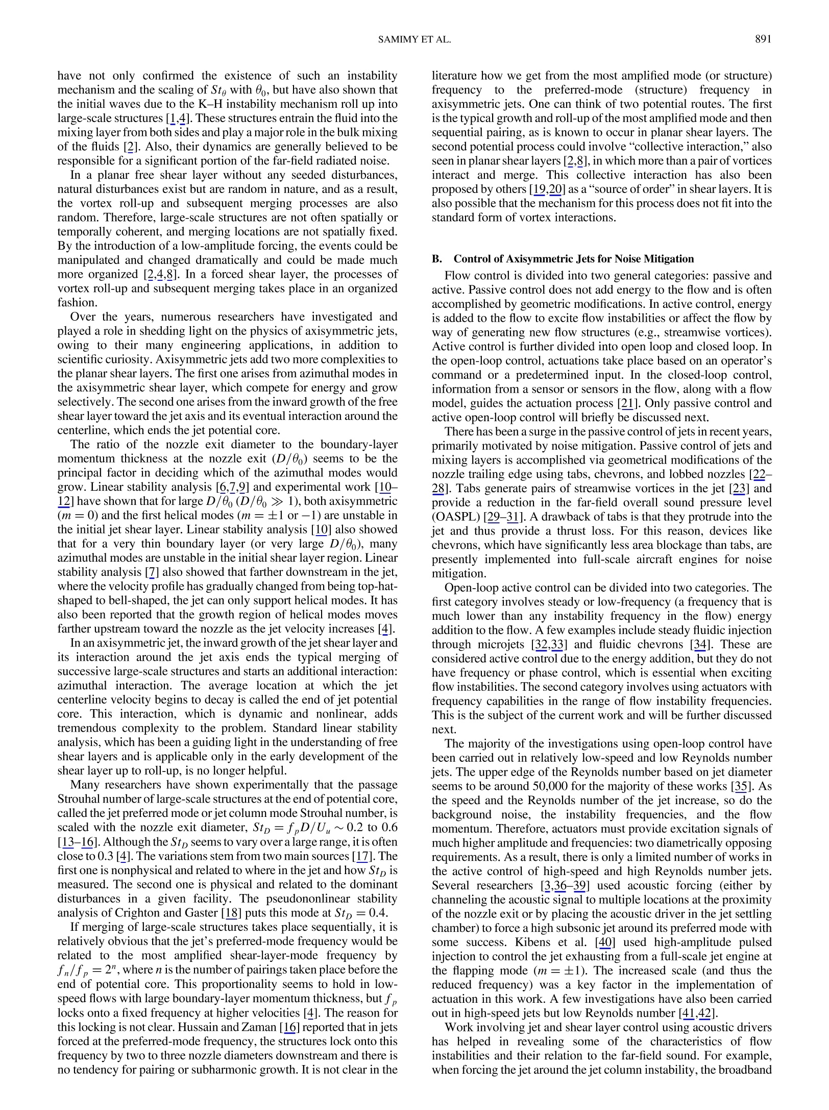
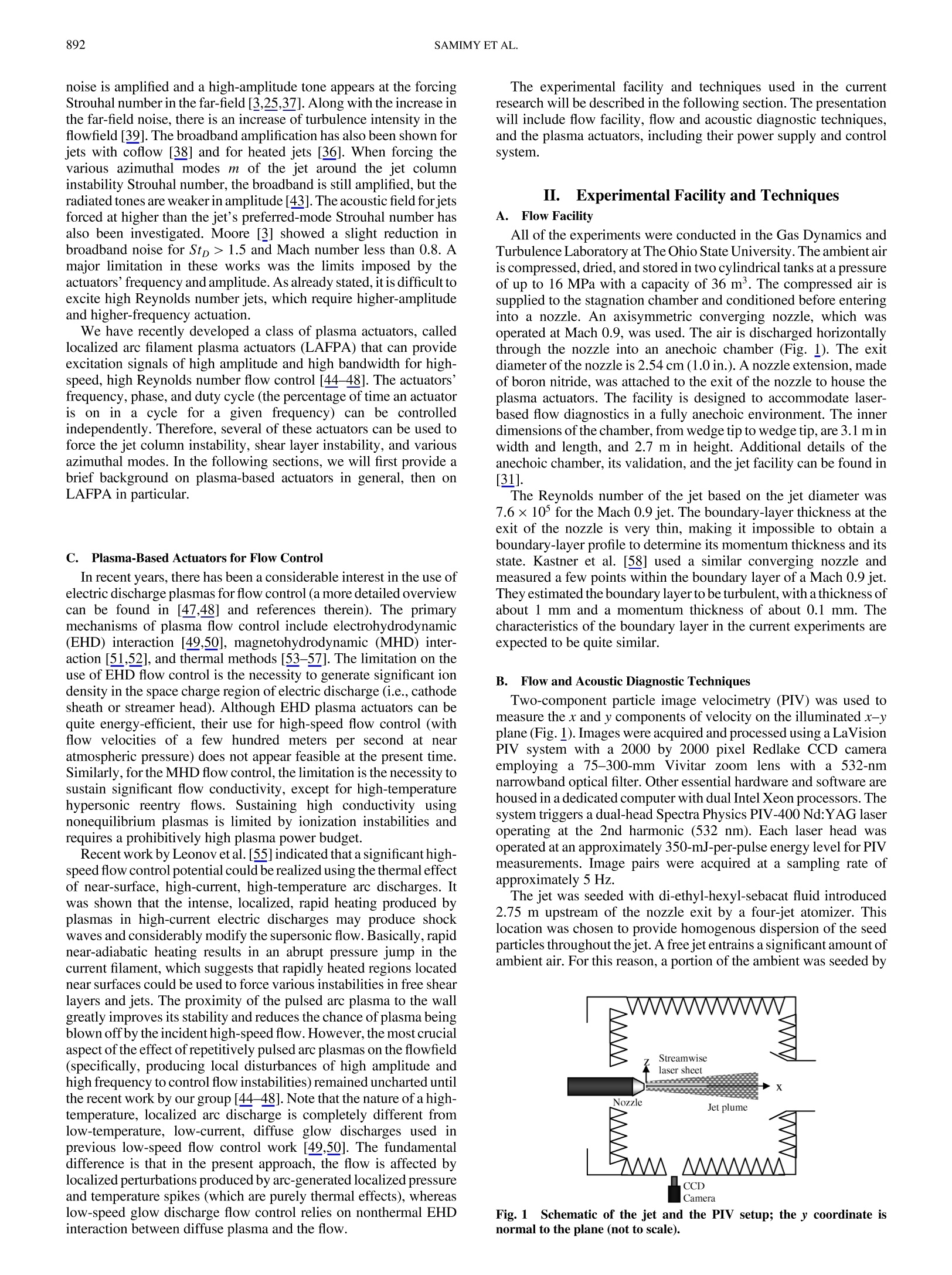
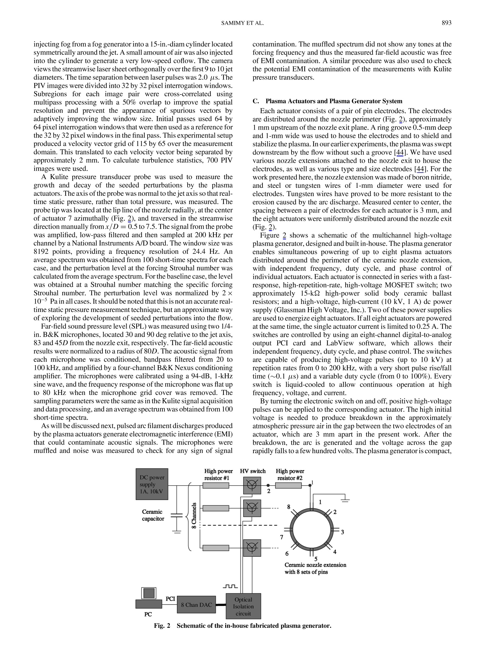
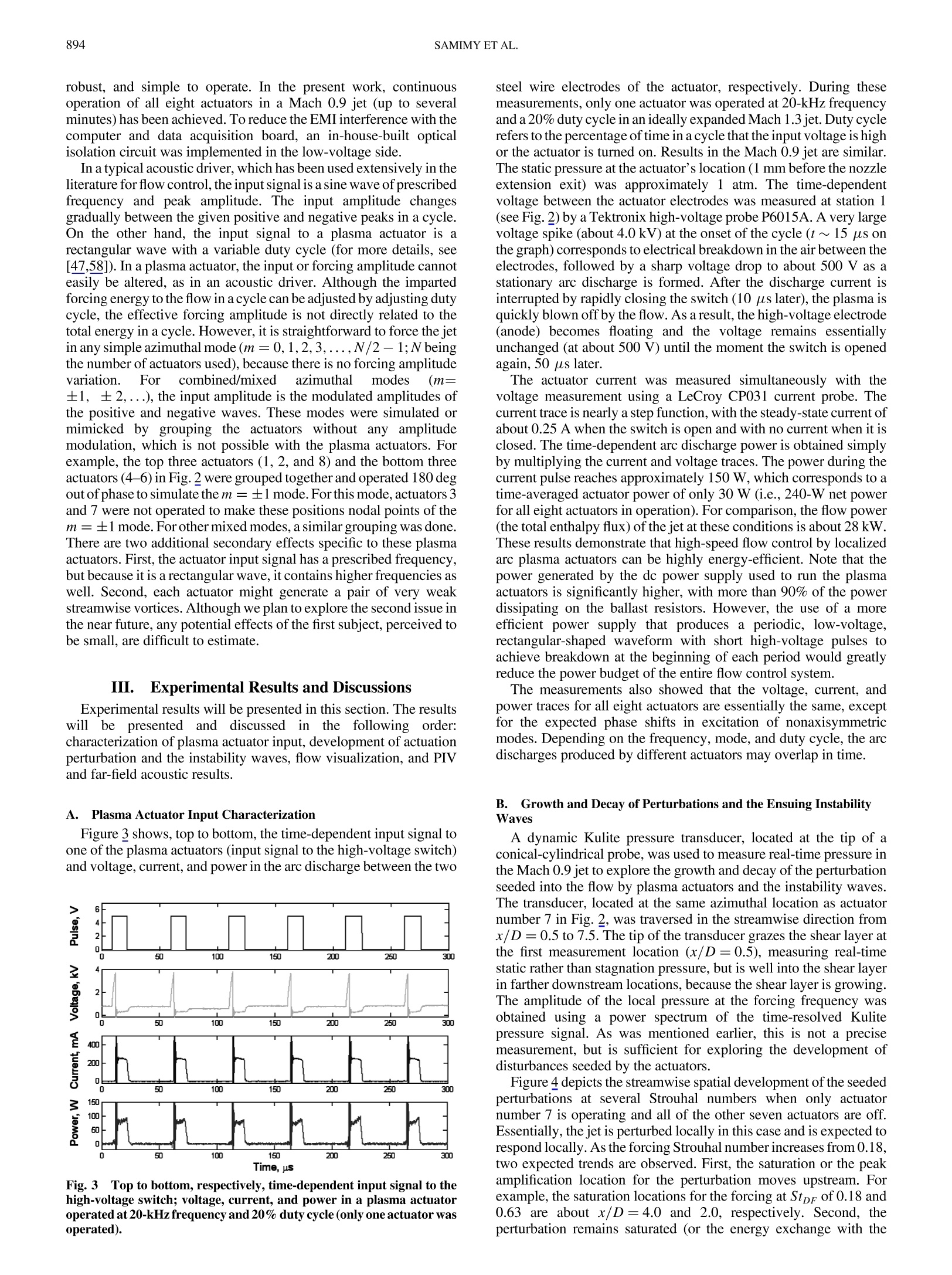
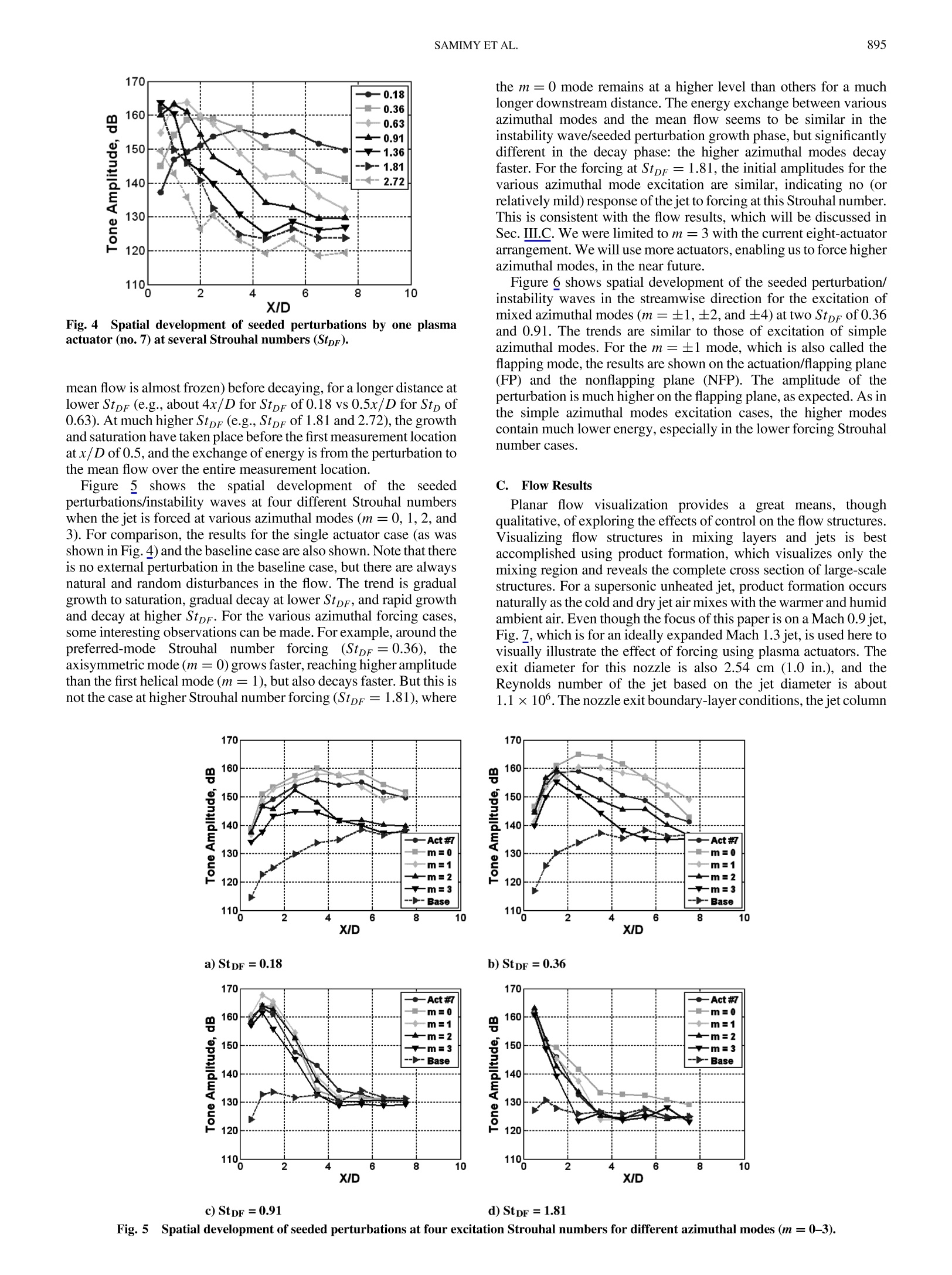
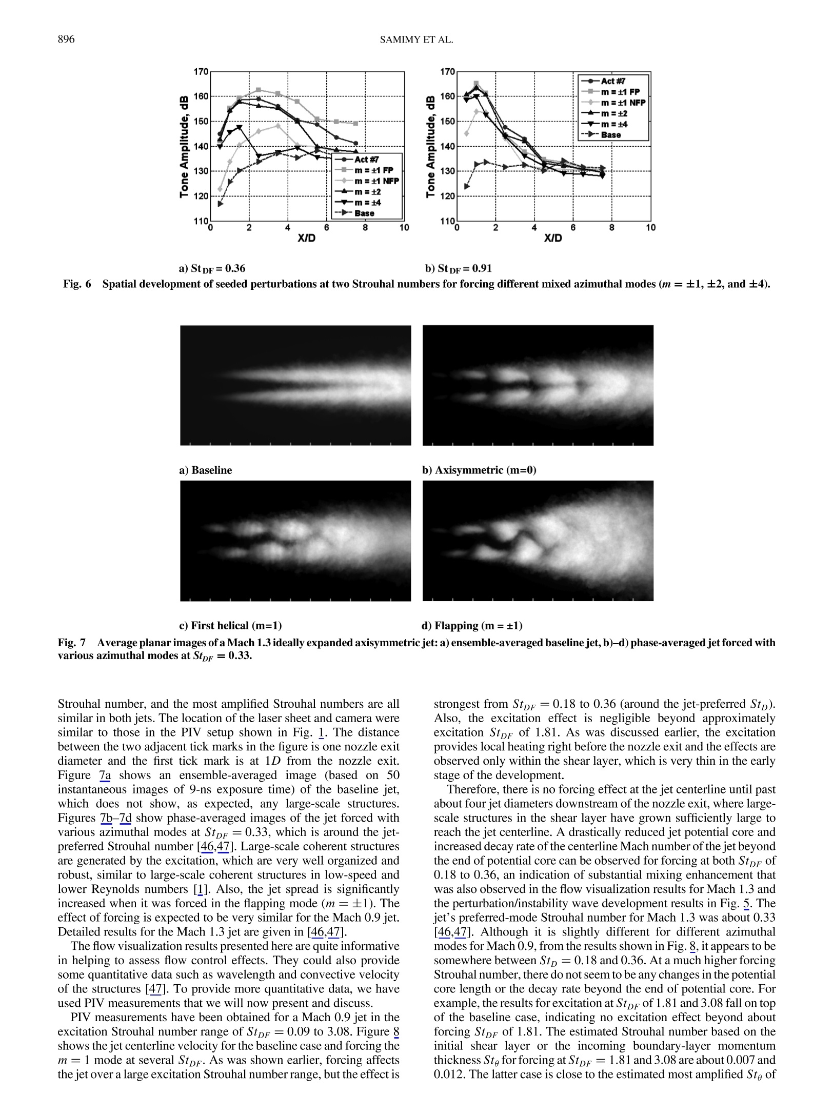
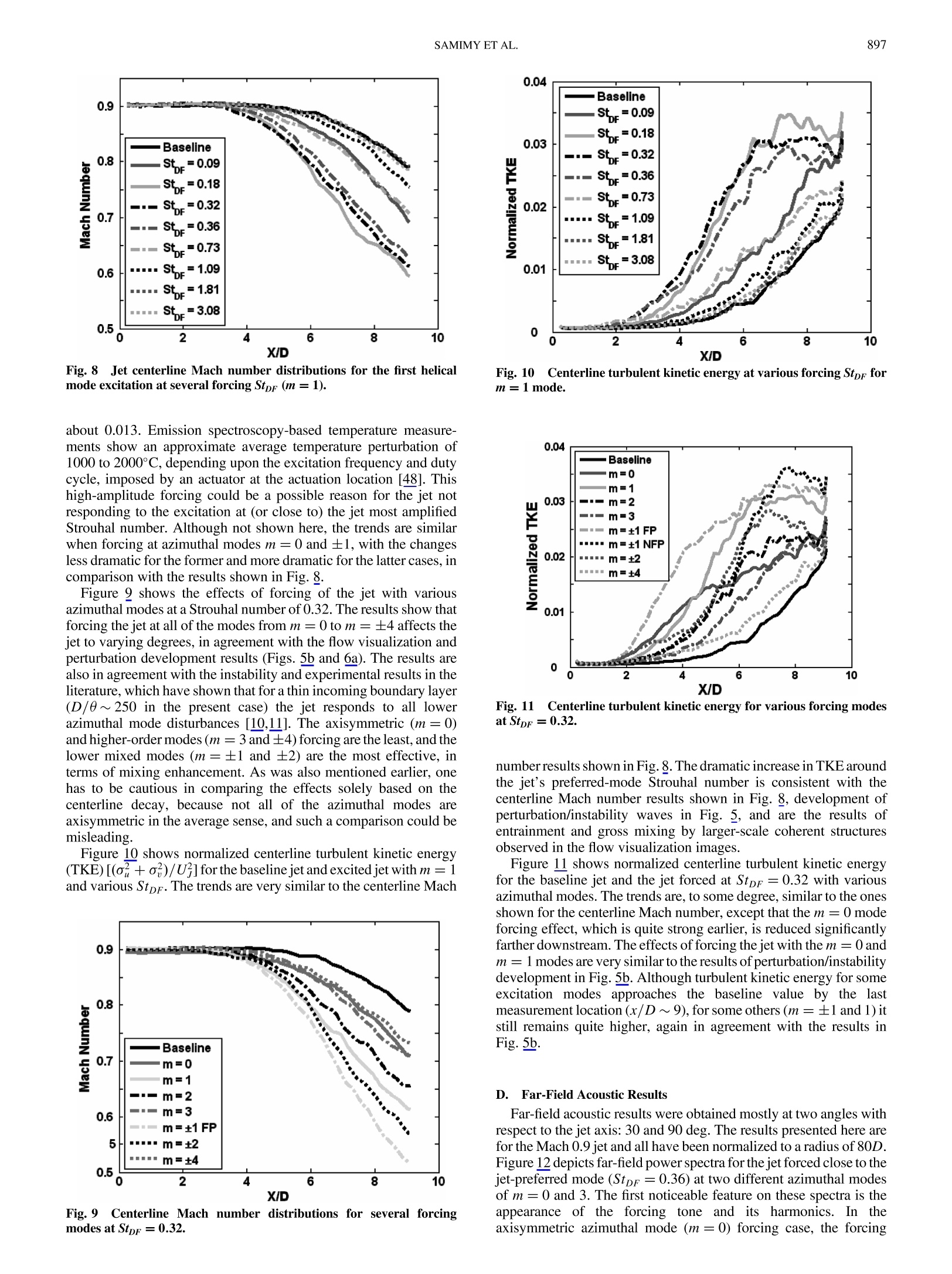
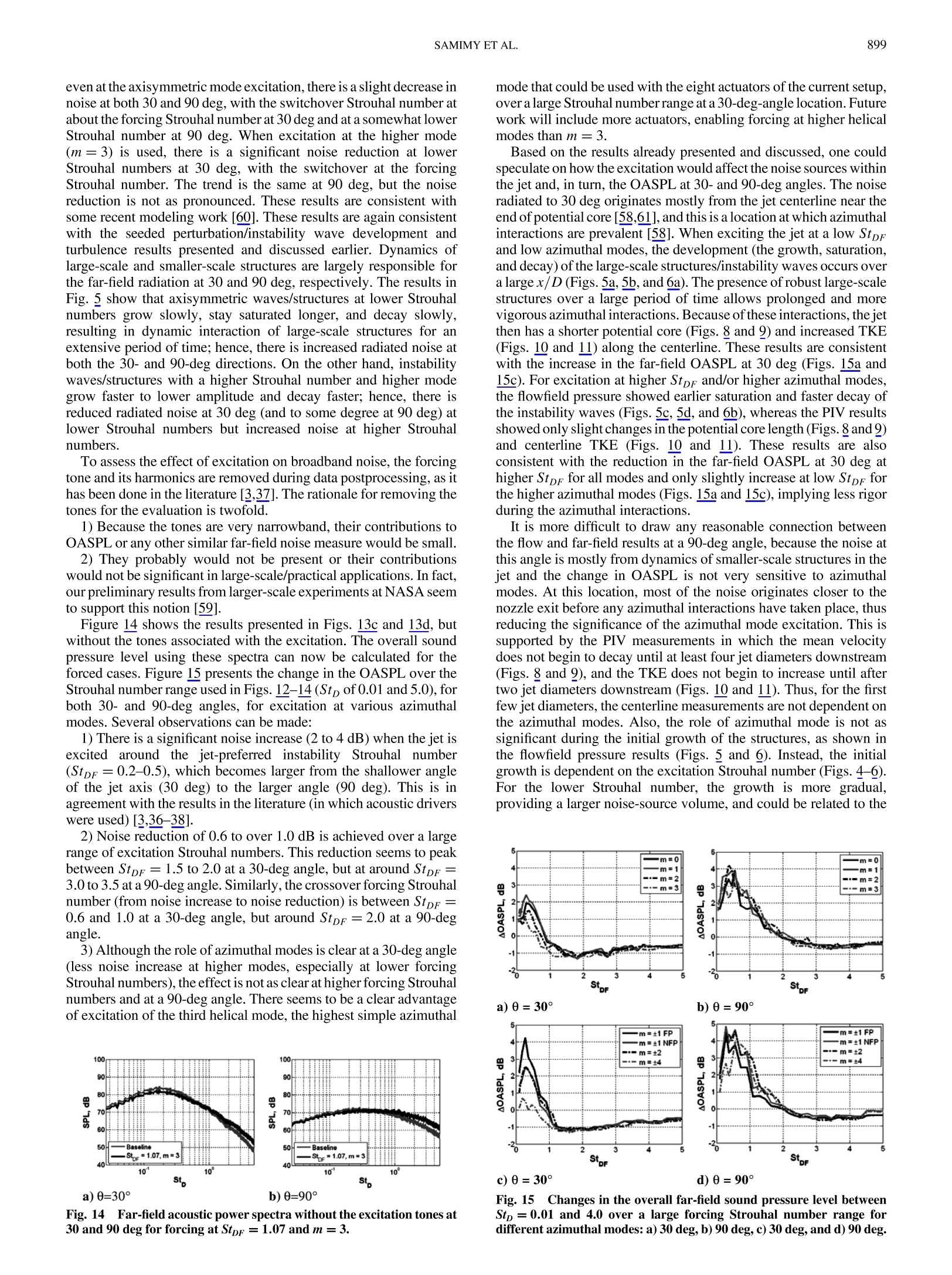
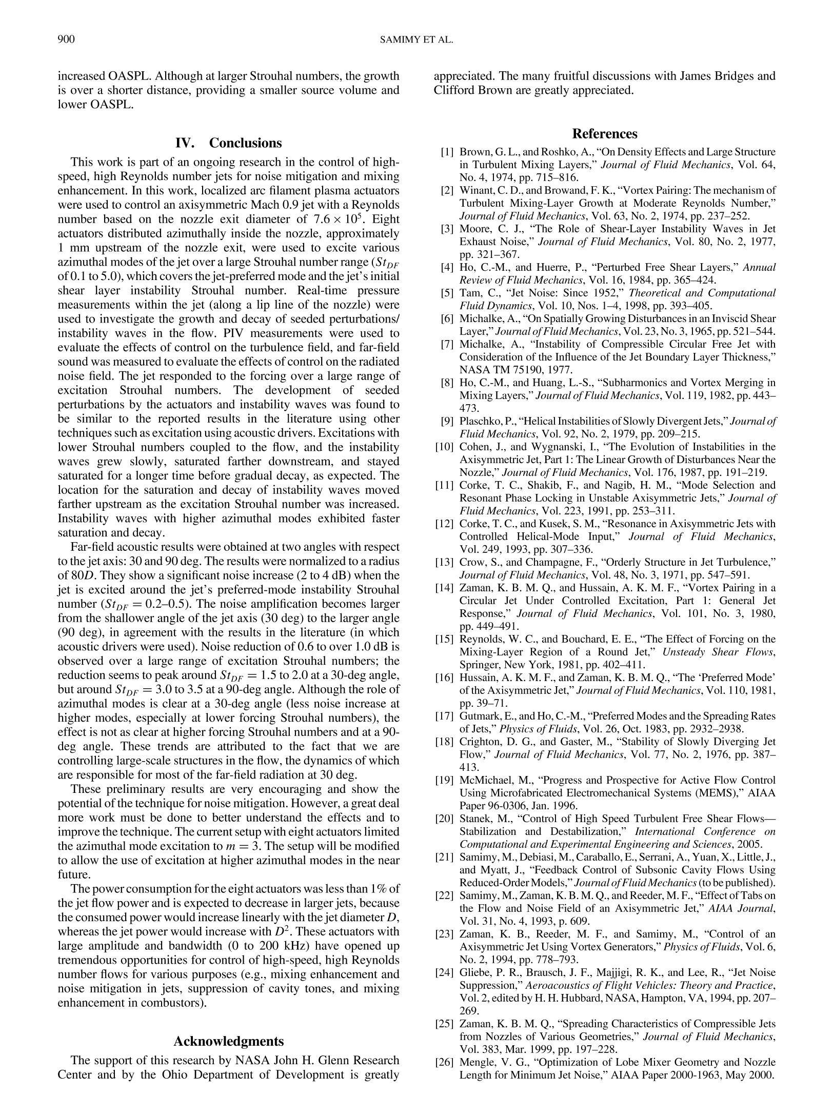
AIAA JOURNALVol. 45,No. 4, April 2007 891SAMIMY ET AL. 890 Active Control of a Mach 0.9 Jet for Noise MitigationUsing Plasma Actuators M. Samimy,*J.-H. Kim,J.Kastner,I. Adamovich,and Y. UtkinThe Ohio State University, Columbus, Ohio 43235-7531 DOI: 10.2514/1.27499 Localized arc filament plasma actuators were used to control an axisymmetric Mach 0.9 jet with a Reynoldsnumber based on the nozzle exit diameter of 7.6×10. Eight actuators, distributed azimuthally inside the nozzle,near the nozzle exit, were used to excite various instabilities and azimuthal modes of the jet over a large Strouhalnumber range (Stpr of0.1 to 5.0). Time-resolved pressure measurements were used to investigate the development ofactuation perturbations in the jet, particle image velocimetry measurements were used to evaluate the control effectson the turbulence field, and far-field sound was measured to evaluate the control effects on the radiated acoustic field.The jet responded to the forcing over a large range of excitation Strouhal numbers with varying degrees. As expected,the low Strouhal number seeded disturbances grew slowly,saturated farther downstream, and stayed saturated for alonger time before decaying gradually. The saturation and decay of the seeded perturbations moved fartherupstream as their Strouhal number was increased. Seeded perturbations with higher azimuthal modes exhibitedfaster decay. Particle image velocimetry results showed that when exciting the jet’s preferred-mode instability atlower azimuthal modes, the jet potential core was shortened and the turbulent kinetic energy was increasedsignificantly. At higher Strouhal numbers and higher azimuthal modes, forcing had less of an impact on the meanvelocity and turbulent kinetic energy. Far-field acoustic results showed a significant noise increase (2 to 4 dB) whenthejet is excited around thejet’s preferred-mode instability Strouhal number(Stpr=0.2-0.5), in agreement with theresults in the literature. Noise reduction of 0.5 to over 1.0 dB is observed over a large excitation Strouhal numberrange; this reduction seems to peak around StpF =1.5 to 2.0 at a 30-deg angle, but around StpF =3.0 to 3.5 at a 90-deg angle. Although forcing the jet with higher azimuthal modes is advantageous for noise mitigation at a 30-degangle and lower Strouhal numbers, the effect is not as clear at higher forcing Strouhal numbers and at a 90-deg angle. Nomenclaturepotential core)Dnozzle exit diameterffmost amplified initial reestream shear lvelocityayer frequencyforcing frequencyxdistance from the nozzle exit along the jet centerlinejet’s prveferreertical distance fromd-mode the jet centerlinefrequencyymomentum thickness at the nozzle exit or at themazimuthal mode numberppressuretrailing edge of the splitter platep=densityDStrouhal number based on the nozzle exit diameter.fD/UOu,o,=rrms fluctuation of the x and y direction velocityStpF=Strouhal number based on the forcing frequency,frD/U, Stp Strouhal number based on the boundary-layermomentum thickness at the nozzle exit, foo/U; Presented as Paper 2703 at the 12th AIAA/CEAS AeroacousticsConference, Cambridge, MA, 8-10 May 2006; received 25 August 2006;revision received 14 December 2006; accepted for publication 3 January2007. Copyright ◎ 2007 by the American Institute of Aeronautics andAstronautics, Inc. All rights reserved. Copies of this paper may be made forpersonal or internal use, on condition that the copier pay the $10.00 per-copyfee to the Copyright Clearance Center, Inc., 222 Rosewood Drive, Danvers,MA 01923; include the code 0001-1452/07 $10.00 in correspondence withthe CCC. *Professor, Director of Gas Dynamics and Turbulence Laboratory,Department of Mechanical Engineering, 2300 West Case Road. AssociateFellow AIAA. Research Associate, Gas Dynamics and Turbulence Laboratory,Department of Mechanical Engineering, 2300 West Case Road. MemberAIAA. Graduate Student, Gas Dynamics and Turbulence Laboratory, Depart-ment of Mechanical Engineering, 2300 West Case Road. Student MemberAIAA. Associate Professor, Nonequilibrium Thermodynamics Laboratory,Department of Mechanical Engineering, 201 West 19th Avenue. AssociateMember AIAA. Postdoctoral Researcher, Nonequilibrium Thermodynamics Laboratory,Department of Mechanical Engineering, 201 West 19th Avenue. MemberAIAA. U; =nozzle exit velocity (jet centerline velocity within the I.Introduction LANAR free shear or mixing layers have received tremendousattention over the past several decades, because these canonicalflows are the building blocks in many practical applications. Thediscovery of large-scale coherent structures in high Reynoldsnumber free shear flows by Brown and Roshko [1] and the realizationthat these structures play a major role in entrainment and bulk mixing[2] and in far-field radiated noise production [3] has changed thenature of the research over the past three decades by putting morefocus on the dynamics and control of these structures. A reviewarticle by Ho and Huerre [4] details most of the early work on thephysics of low-speed free shear flows, as well as their control, overabout two decades. A review article by Tam [5] details the work in jetnoise and the role of large-scale structures. A. Instability of Free Shear Layers and Axisymmetric Jets A planar free shear layer is known to be unstable and acts like an amplifier of disturbances in the flow over a range of frequencies. Theinstability of free shear layers is referred to as Kelvin-Helmholtz (K-H) instability. In sufficiently high Reynolds numbers, the effect ofviscosity in the amplification of disturbances is relatively small, andthus the instability is also called inviscid instability. Detailed linearstability analysis [6,7] over the years has shown that the mostamplified Strouhal number scales with the momentum thickness ofthe boundary layer at the trailing edge of the splitter plate(Stg=fneo/U.。~0.013). Subsequent experimental investigations have not only confirmed the existence of such an instabilitymechanism and the scaling of Stg with 0, but have also shown thatthe initial waves due to the K-H instability mechanism roll up intolarge-scale structures [1,4]. These structures entrain the fluid into themixing layer from both sides and play a major role in the bulk mixingof the fluids [2]. Also, their dynamics are generally believed to beresponsible for a significant portion of the far-field radiated noise. In a planar free shear layer without any seeded disturbances,natural disturbances exist but are random in nature, and as a result,the vortex roll-up and subsequent merging processes are alsorandom. Therefore, large-scale structures are not often spatially ortemporally coherent, and merging locations are not spatially fixed.By the introduction of a low-amplitude forcing, the events could bemanipulated and changed dramatically and could be made muchmore organized [2,4,8]. In a forced shear layer, the processes ofl4vortex roll-up and subsequent merging takes place in an organizedfashion. Over the years, numerous researchers have investigated andplayed a role in shedding light on the physics of axisymmetric jets,owing to their many engineering applications, in addition toscientific curiosity. Axisymmetric jets add two more complexities tothe planar shear layers. The first one arises from azimuthal modes inthe axisymmetric shear layer, which compete for energy and growselectively. The second one arises from the inward growth of the freeshear layer toward the jet axis and its eventual interaction around thecenterline, which ends the jet potential core. The ratio of the nozzle exit diameter to the boundary-layermomentum thickness at the nozzle exit (D/) seems to be theprincipal factor in deciding which of the azimuthal modes wouldgrow. Linear stability analysis [6,7,9] and experimental work [10-12] have shown that for large D/0 (D/0>1), both axisymmetric(m =0) and the first helical modes (m =±1 or-1) are unstable inthe initial jet shear layer. Linear stability analysis [10] also showedthat for a very thin boundary layer (or very large D/0), manyazimuthal modes are unstable in the initial shear layer region. Linearstability analysis [Z] also showed that farther downstream in the jet,where the velocity profile has gradually changed from being top-hat-shaped to bell-shaped, the jet can only support helical modes. It hasalso been reported that the growth region of helical modes movesfarther upstream toward the nozzle as the jet velocity increases [4]. In an axisymmetric jet, the inward growth of the jet shear layer andits interaction around the jet axis ends the typical merging ofsuccessive large-scale structures and starts an additional interaction:azimuthal interaction. The average location at which the jetcenterline velocity begins to decay is called the end of jet potentialcore. This interaction, which is dynamic and nonlinear, addstremendous complexity to the problem. Standard linear stabilityanalysis, which has been a guiding light in the understanding of freeshear layers and is applicable only in the early development of theshear layer up to roll-up, is no longer helpful. Many researchers have shown experimentally that the passageStrouhal number of large-scale structures at the end of potential core,called the jet preferred mode or jet column mode Strouhal number, isscaled with the nozzle exit diameter, Stp=f,D/U~0.2 to 0.6[13-16]. Although the Stp seems to vary over alarge range, it is oftenclose to 0.3 [4]. The variations stem from two main sources [17].Thefirst one is nonphysical and related to where in the jet and how Stp ismeasured. The second one is physical and related to the dominantdisturbances in a given facility. The pseudononlinear stabilityanalysis of Crighton and Gaster [18] puts this mode at Stp=0.4. If merging of large-scale structures takes place sequentially, it isrelatively obvious that the jet’s preferred-mode frequency would berelated to the most amplified shear-layer-mode frequency byfn/fp=2", where n is the number of pairings taken place before theend of potential core. This proportionality seems to hold in low-speed flows with large boundary-layer momentum thickness, but f,locks onto a fixed frequency at higher velocities [4]. The reason forthis locking is not clear. Hussain and Zaman [16] reported that in jetsforced at the preferred-mode frequency, the structures lock onto thisfrequency by two to three nozzle diameters downstream and there isno tendency for pairing or subharmonic growth. It is not clear in the B. Control of Axisymmetric Jets for Noise Mitigation Flow control is divided into two general categories: passive andactive. Passive control does not add energy to the flow and is oftenaccomplished by geometric modifications. In active control, energyis added to the flow to excite flow instabilities or affect the flow byway of generating new flow structures (e.g., streamwise vortices).Active control is further divided into open loop and closed loop. Inthe open-loop control, actuations take place based on an operator’scommand or a predetermined input. In the closed-loop control,information from a sensor or sensors in the flow, along with a flowmodel, guides the actuation process [21]. Only passive control andactive open-loop control will briefly be discussed next. There has been a surge in the passive control of jets in recent years,primarily motivated by noise mitigation. Passive control of jets andmixing layers is accomplished via geometrical modifications of thenozzle trailing edge using tabs, chevrons, and lobbed nozzles [22-28]. Tabs generate pairs of streamwise vortices in the jet [23] andprovide a reduction in the far-field overall sound pressure level(OASPL) [29-31]. A drawback of tabs is that they protrude into thejet and thus provide a thrust loss. For this reason, devices likechevrons, which have significantly less area blockage than tabs, arepresently implemented into full-scale aircraft engines for noisemitigation. Open-loop active control can be divided into two categories. Thefirst category involves steady or low-frequency (a frequency that ismuch lower than any instability frequency in the flow) energyaddition to the flow. A few examples include steady fluidic injectionthrough microjets [32,33] and fluidic chevrons [34]. These areconsidered active control due to the energy addition, but they do nothave frequency or phase control, which is essential when excitingflow instabilities. The second category involves using actuators withfrequency capabilities in the range of flow instability frequencies.This is the subject of the current work and will be further discussednext. Work involving jet and shear layer control using acoustic drivershas helped in revealing some of the characteristics of flowinstabilities and their relation to the far-field sound. For example,when forcing the jet around the jet column instability, the broadband noise is amplified and a high-amplitude tone appears at the forcingStrouhal number in the far-field [3,25,37]. Along with the increase inthe far-field noise, there is an increase of turbulence intensity in theflowfield [39]. The broadband amplification has also been shown forjets with coflow [38] and for heated jets [36]. When forcing thevarious azimuthal modes m of the jet around the jet columninstability Strouhal number, the broadband is still amplified, but theradiated tones are weaker in amplitude [43]. The acoustic field for jetsforced at higher than the jet’s preferred-mode Strouhal number hasalso been investigated. Moore [3] showed a slight reduction inbroadband noise for Stp> 1.5 and Mach number less than 0.8. Amajor limitation in these works was the limits imposed by theactuators’frequency and amplitude. As already stated, it is difficult toexcite high Reynolds number jets, which require higher-amplitudeand higher-frequency actuation. We have recently developed a class of plasma actuators, calledlocalized arc filament plasma actuators (LAFPA) that can provideexcitation signals of high amplitude and high bandwidth for high-speed, high Reynolds number flow control [44-48]. The actuators’frequency, phase, and duty cycle (the percentage of time an actuatoris on in a cycle for a given frequency) can be controlledindependently. Therefore, several of these actuators can be used toforce the jet column instability, shear layer instability, and variousazimuthal modes. In the following sections, we will first provide abrief background on plasma-based actuators in general, then onLAFPA in particular. C. Plasma-Based Actuators for Flow Control In recent years, there has been a considerable interest in the use ofelectric discharge plasmas for flow control (a more detailed overviewcan be found in [47,48] and references therein). The primarymechanisms of plasma flow control include electrohydrodynamic(EHD) interaction [49,50], magnetohydrodynamic (MHD) inter-action [51,52], and thermal methods [53-57]. The limitation on theuse of EHD flow control is the necessity to generate significant iondensity in the space charge region of electric discharge (i.e., cathodesheath or streamer head). Although EHD plasma actuators can bequite energy-efficient, their use for high-speed flow control (withflow velocities of a few hundred meters per second at nearatmospheric pressure) does not appear feasible at the present time.Similarly, for the MHD flow control, the limitation is the necessity tosustain significant flow conductivity, except for high-temperaturehypersonic reentry flows. Sustaining high conductivity usingnonequilibrium plasmas is limited by ionization instabilities andrequires a prohibitively high plasma power budget. Recent work by Leonov et al.[55] indicated that a significanthigh-speed flow control potential could be realized using the thermal effectof near-surface, high-current, high-temperature arc discharges. Itwas shown that the intense, localized, rapid heating produced byplasmas in high-current electric discharges may produce shockwaves and considerably modify the supersonic flow. Basically, rapidnear-adiabatic heating results in an abrupt pressure jump in thecurrent filament, which suggests that rapidly heated regions locatednear surfaces could be used to force various instabilities in free shearlayers and jets. The proximity of the pulsed arc plasma to the wallgreatly improves its stability and reduces the chance of plasma beingblown off by the incident high-speed flow. However, the most crucialaspect of the effect of repetitively pulsed arc plasmas on the flowfield(specifically, producing local disturbances of high amplitude andhigh frequency to control flow instabilities) remained uncharted untilthe recent work by our group [44-48]. Note that the nature of a high-temperature, localized arc discharge is completely different fromlow-temperature, low-current, diffuse glow discharges used inprevious low-speed flow control work[49,50]. The fundamentaldifference is that in the present approach, the flow is affected bylocalized perturbations produced by arc-generated localized pressureand temperature spikes (which are purely thermal effects), whereaslow-speed glow discharge flow control relies on nonthermal EHDinteraction between diffuse plasma and the flow. The experimental facility and techniques used in the currentresearch will be described in the following section. The presentationwill include flow facility, flow and acoustic diagnostic techniques,and the plasma actuators, including their power supply and controlsystem. I. Experimental Facility and Techniques A. Flow Facility All of the experiments were conducted in the Gas Dynamics andTurbulence Laboratory at The Ohio State University. The ambient airis compressed, dried, and stored in two cylindrical tanks at a pressureof up to 16 MPa with a capacity of 36 m. The compressed air issupplied to the stagnation chamber and conditioned before enteringinto a nozzle. An axisymmetric converging nozzle, which wasoperated at Mach 0.9, was used. The air is discharged horizontallythrough the nozzle into an anechoic chamber (Fig.1). The exitdiameter of the nozzle is 2.54 cm (1.0 in.). A nozzle extension, madeof boron nitride, was attached to the exit of the nozzle to house theplasma actuators. The facility is designed to accommodate laser-based flow diagnostics in a fully anechoic environment. The innerdimensions of the chamber, from wedge tip to wedge tip, are 3.1 m inwidth and length, and 2.7 m in height. Additional details of theanechoic chamber, its validation, and the jet facility can be found in[31]. The Reynolds number of the jet based on the jet diameter was7.6×10° for the Mach 0.9 jet. The boundary-layer thickness at theexit of the nozzle is very thin, making it impossible to obtain aboundary-layer profile to determine its momentum thickness and itsstate. Kastner et al. [58] used a similar converging nozzle andmeasured a few points within the boundary layer of a Mach 0.9 jet.They estimated the boundary layer to be turbulent, with a thickness ofabout 1 mm and a momentum thickness of about 0.1 mm. Thecharacteristics of the boundary layer in the current experiments areexpected to be quite similar. B. Flow and Acoustic Diagnostic Techniques Two-component particle image velocimetry (PIV) was used tomeasure the x and y components of velocity on the illuminated x-yplane(Fig. 1). Images were acquired and processed using a LaVisionPIV system with a 2000 by 2000 pixel Redlake CCD cameraemployinga 75-300-mm Vivitar zoom lens with a 532-nmnarrowband optical filter. Other essential hardware and software arehoused in a dedicated computer with dual Intel Xeon processors. Thesystem triggers a dual-head Spectra Physics PIV-400Nd:YAG laseroperating at the 2nd harmonic (532 nm). Each laser head wasoperated at an approximately 350-mJ-per-pulse energy level for PIVmeasurements. Image pairs were acquired at a sampling rate ofapproximately 5 Hz. The jet was seeded with di-ethyl-hexyl-sebacat fluid introduced2.75 m upstream of the nozzle exit by a four-jet atomizer. Thislocation was chosen to provide homogenous dispersion of the seedparticles throughout the jet. A free jet entrains a significant amount ofambient air. For this reason, a portion of the ambient was seeded by Camera Fig.1Schematic of the jet and the PIV setup; the y coordinate isnormal to the plane (not to scale). injecting fog from a fog generator into a 15-in.-diam cylinder locatedsymmetrically around the jet. A small amount of air was also injectedinto the cylinder to generate a very low-speed coflow. The cameraviews the streamwise laser sheet orthogonally over the first 9 to 10 jetdiameters. The time separation between laser pulses was 2.0 us. ThePIV images were divided into 32 by 32 pixel interrogation windows.Subregions for each image pair were cross-correlated usingmultipass processing with a 50% overlap to improve the spatialresolution and prevent the appearance of spurious vectors byadaptively improving the window size. Initial passes used 64 by64 pixel interrogation windows that were then used as a reference forthe 32 by 32 pixel windows in the final pass. This experimental setupproduced a velocity vector grid of 115 by 65 over the measurementdomain. This translated to each velocity vector being separated byapproximately 2 mm. To calculate turbulence statistics, 700 PIVimages were used. A Kulite pressure transducer probe was used to measure thegrowth and decay of the seeded perturbations by the plasmaactuators. The axis of the probe was normal to thejet axis so that real-time static pressure, rather than total pressure, was measured. Theprobe tip was located at the lip line of the nozzle radially, at the centerof actuator 7 azimuthally (Fig. 2), and traversed in the streamwisedirection manually fromx/D= 0.5 to 7.5. The signal from the probewas amplified, low-pass filtered and then sampled at 200 kHz perchannel by a National Instruments A/D board. The window size was8192 points, providing a frequency resolution of 24.4 Hz. Anaverage spectrum was obtained from 100 short-time spectra for eachcase, and the perturbation level at the forcing Strouhal number wascalculated from the average spectrum. For the baseline case, the levelwas obtained at a Strouhal number matching the specific forcingStrouhal number. The perturbation level was normalized by 2×10⁻⁵ Pa in all cases. It should be noted that this is not an accurate real-time static pressure measurement technique, but an approximate way of exploring the development of seeded perturbations into the flow. Far-field sound pressure level (SPL) was measured using two 1/4- in. B&K microphones, located 30 and 90 deg relative to the jet axis, 83 and 45D from the nozzle exit, respectively. The far-field acoustic results were normalized to a radius of 80D. The acoustic signal from each microphone was conditioned, bandpass filtered from 20 to 100 kHz, and amplified by a four-channel B&K Nexus conditioning amplifier. The microphones were calibrated using a 94-dB, 1-kHz sine wave, and the frequency response of the microphone was flat up to 80 kHz when the microphone grid cover was removed. The sampling parameters were the same as in the Kulite signal acquisition and data processing,and an average spectrum was obtained from 100 short-time spectra. As will be discussed next, pulsed arc filament discharges producedby the plasma actuators generate electromagnetic interference (EMI)that could contaminate acoustic signals. The microphones weremuffled and noise was measured to check for any sign of signal contamination. The muffled spectrum did not show any tones at theforcing frequency and thus the measured far-field acoustic was freeof EMI contamination. A similar procedure was also used to checkthe potential EMI contamination of the measurements with Kulitepressure transducers. C. Plasma Actuators and Plasma Generator System Each actuator consists of a pair of pin electrodes.The electrodesare distributed around the nozzle perimeter (Fig.2), approximately1 mm upstream of the nozzle exit plane. A ring groove 0.5-mm deepand 1-mm wide was used to house the electrodes and to shield andstabilize the plasma. In our earlier experiments, the plasma was sweptdownstream by the flow without such a groove [44]. We have usedvarious nozzle extensions attached to the nozzle exit to house theelectrodes, as well as various type and size electrodes [44]. For thework presented here, the nozzle extension was made of boron nitride,and steel or tungsten wires of 1-mm diameter were used forelectrodes. Tungsten wires have proved to be more resistant to theerosion caused by the arc discharge. Measured center to center, thespacing between a pair of electrodes for each actuator is 3 mm, andthe eight actuators were uniformly distributed around the nozzle exit(Fig.2). Figure 2 shows a schematic of the multichannel high-voltageplasma generator, designed and built in-house. The plasma generatorenables simultaneous powering of up to eight plasma actuatorsdistributed around the perimeter of the ceramic nozzle extension,with independent frequency, duty cycle, and phase control ofindividual actuators.Each actuator is connected in series with a fast-response, high-repetition-rate, high-voltage MOSFET switch; twoapproximately 15-k2 high-power solid body ceramic ballastresistors; and a high-voltage, high-current (10 kV, 1 A) de powersupply (Glassman High Voltage, Inc.). Two of these power suppliesare used to energize eight actuators. If all eight actuators are poweredat the same time, the single actuator current is limited to 0.25 A. Theswitches are controlled by using an eight-channel digital-to-analogoutput PCI card and LabView software, which allows theirindependent frequency, duty cycle, and phase control. The switchesare capable of producing high-voltage pulses (up to 10 kV) atrepetition rates from 0 to 200 kHz, with a very short pulse rise/falltime (~0.1us) and a variable duty cycle (from 0 to 100%). Everyswitch is liquid-cooled to allow continuous operation at highfrequency, voltage, and current. By turning the electronic switch on and off, positive high-voltagepulses can be applied to the corresponding actuator. The high initialvoltage is needed to produce breakdown in the approximatelyatmospheric pressure air in the gap between the two electrodes of anactuator, which are 3 mm apart in the present work. After thebreakdown, the arc is generated and the voltage across the gaprapidly falls to a few hundred volts. The plasma generator is compact, Fig.2SSchematic of the in-house fabricated plasma generator. robust, and simple to operate. In the present work, continuousoperation of all eight actuators in a Mach 0.9 jet (up to severalminutes) has been achieved. To reduce the EMI interference with thecomputer and data acquisition board, an in-house-built opticalisolation circuit was implemented in the low-voltage side. In a typical acoustic driver, which has been used extensively in theliterature for flow control, the input signal is a sine wave of prescribedfrequency and peak amplitude. The input amplitude changesgradually between the given positive and negative peaks in a cycle.On the other hand, the input signal to a plasma actuator is arectangular wave with a variable duty cycle (for more details, see[47,58]). In a plasma actuator, the input or forcing amplitude cannoteasily be altered, as in an acoustic driver. Although the impartedforcing energy to the flow in a cycle can be adjusted by adjusting dutycycle, the effective forcing amplitude is not directly related to thetotal energy in a cycle.However, it is straightforward to force the jetin any simple azimuthal mode (m=0,1,2,3,...,N/2-1;N beingthe number of actuators used), because there is no forcing amplitudevariation. FForr combined/mixedazimuthal modes (m=±1,±2,...), the input amplitude is the modulated amplitudes ofthe positive and negative waves. These modes were simulated ormimicked by grouping the actuators without any amplitudemodulation, which is not possible with the plasma actuators. Forexample, the top three actuators (1, 2, and 8) and the bottom threeactuators (4-6) in Fig. 2 were grouped together and operated 180 degout of phase to simulate the m =±1 mode. For this mode, actuators 3and 7 were not operated to make these positions nodal points of them =±1 mode. For other mixed modes, a similar grouping was done.There are two additional secondary effects specific to these plasmaactuators. First, the actuator input signal has a prescribed frequency,but because it is a rectangular wave, it contains higher frequencies aswell. Second, each actuator might generate a pair of very weakstreamwise vortices. Although we plan to explore the second issue inthe near future, any potential effects of the first subject, perceived tobe small, are difficult to estimate. III. Experimental Results and Discussions Experimental results will be presented in this section. The resultswilllbepresented and1 (discussedinthe llowing oorrdder:characterization of plasma actuator input, development of actuationperturbation and the instability waves, flow visualization, and PIVand far-field acoustic results. A. Plasma Actuator Input Characterization Figure 3 shows, top to bottom, the time-dependent input signal toone of the plasma actuators (input signal to the high-voltage switch)and voltage, current, and power in the arc discharge between the two Fig. 3 Top to bottom, respectively, time-dependent input signal to thehigh-voltage switch; voltage, current, and power in a plasma actuatoroperated at 20-kHz frequency and 20% duty cycle(only one actuator wasoperated). steel wire electrodes of the actuator, respectively. During thesemeasurements, only one actuator was operated at 20-kHz frequencyand a 20% duty cycle in an ideally expanded Mach 1.3jet. Duty cyclerefers to the percentage of time in a cycle that the input voltage is highisfor the actuator is turned on. Results in the Mach 0.9 jet are similar.The static pressure at the actuator’s location (1 mm before the nozzleextension exit) was approximately 1 atm. The time-dependentvoltage between the actuator electrodes was measured at station 1(see Fig.2) by a Tektronix high-voltage probe P6015A. A very largevoltage spike (about 4.0kV) at the onset of the cycle (t~15 us onthe graph) corresponds to electrical breakdown in the air between theelectrodes, followed by a sharp voltage drop to about 500 V as astationary arc discharge is formed. After the discharge current isinterrupted by rapidly closing the switch (10 us later), the plasma isquickly blown off by the flow. As a result, the high-voltage electrode(anode) becomes floating and the voltage remains essentiallyunchanged (at about 500 V) until the moment the switch is openedagain, 50 jus later. The actuator current was measured simultaneously with thevoltage measurement using a LeCroy CP031 current probe. Thecurrent trace is nearly a step function, with the steady-state current ofabout 0.25 A when the switch is open and with no current when it isclosed. The time-dependent arc discharge power is obtained simplyby multiplying the current and voltage traces. The power during thecurrent pulse reaches approximately 150 W, which corresponds to atime-averaged actuator power of only 30 W (i.e., 240-W net powerfor all eight actuators in operation). For comparison, the flow power(the total enthalpy flux) of the jet at these conditions is about 28 kW.These results demonstrate that high-speed flow control by localizedarc plasma actuators can be highly energy-efficient. Note that thepower generated by the dc power supply used to run the plasmaactuators is significantly higher, with more than 90% of the powerdissipating on the ballast resistors. However, the use of a moreefficient power supply that produces a periodic, low-voltage,rectangular-shaped waveform with short high-voltage pulses toachieve breakdown at the beginning of each period would greatlyreduce the power budget of the entire flow control system. The measurements also showed that the voltage, current, andpower traces for all eight actuators are essentially the same, exceptfor the expected phase shifts in excitation of nonaxisymmetricmodes. Depending on the frequency, mode, and duty cycle, the arcdischarges produced by different actuators may overlap in time. B. Growth and Decay of Perturbations and the Ensuing InstabilityWaves A dynamic Kulite pressure transducer, located at the tip of aconical-cylindrical probe, was used to measure real-time pressure inthe Mach 0.9 jet to explore the growth and decay of the perturbationseeded into the flow by plasma actuators and the instability waves.The transducer, located at the same azimuthal location as actuatornumber 7 in Fig. 2, was traversed in the streamwise direction fromx/D=0.5to 7.5. The tip of the transducer grazes the shear layer atthe first measurement location (x/D=0.5), measuring real-timestatic rather than stagnation pressure, but is well into the shear layerin farther downstream locations, because the shear layer is growing.The amplitude of the local pressure at the forcing frequency wasobtained using a power spectrum of the time-resolved Kulitepressure signal. As was mentioned earlier, this is not a precisemeasurement, but is sufficient for exploring the development ofdisturbances seeded by the actuators. Figure 4 depicts the streamwise spatial development of the seededperturbations at several Strouhal numbers when only actuatornumber 7 is operating and all of the other seven actuators are off.Essentially, the jet is perturbed locally in this case and is expected torespond locally. As the forcing Strouhal number increases from 0.18,two expected trends are observed. First, the saturation or the peakamplification location for the perturbation moves upstream. Forexample, the saturation locations for the forcing at Stpr of 0.18 and0.63 are about x/D=4.0 and 2.0, respectively. Second, theperturbation remains saturated (or the energy exchange with the Fig. 4 Spatial development of seeded perturbations by one plasmaactuator (no.7) at several Strouhal numbers (Stpr). mean flow is almost frozen) before decaying, for a longer distance atlower Stpr (e.g., about 4x/D for Stpr of 0.18 vs 0.5x/D for Stp of0.63). At much higher Stpr (e.g.,Stpr of 1.81 and 2.72), the growthand saturation have taken place before the first measurement locationatx/D of0.5, and the exchange of energy is from the perturbation tothe mean flow over the entire measurement location. Figure 5 shows the spatial development of the seededperturbations/instability waves at four different Strouhal numberswhen the jet is forced at various azimuthal modes (m=0, 1,2, and3). For comparison, the results for the single actuator case (as wasshown in Fig. 4) and the baseline case are also shown. Note that thereis no external perturbation in the baseline case, but there are alwaysnatural and random disturbances in the flow. The trend is gradualgrowth to saturation, gradual decay at lower StpF, and rapid growthand decay at higher Stpp. For the various azimuthal forcing cases,some interesting observations can be made. For example, around thepreferred-mode Strouhal number forcing (Stpr=0.36), theaxisymmetric mode (m=0) grows faster,reaching higher amplitudethan the first helical mode (m=1), but also decays faster. But this isnot the case at higher Strouhal number forcing (StpF=1.81), where 170: them=0 mode remains at a higher level than others for a muchlonger downstream distance. The energy exchange between variousazimuthal modes and the mean flow seems to be similar in theinstability wave/seeded perturbation growth phase, but significantlydifferent in the decay phase: the higher azimuthal modes decayfaster. For the forcing at StpF=1.81, the initial amplitudes for thevarious azimuthal mode excitation are similar, indicating no (orrelatively mild) response ofthe jet to forcing at this Strouhal number.This is consistent with the flow results, which will be discussed inSec.ⅢI.C. We were limited to m =3 with the current eight-actuatorarrangement. We will use more actuators, enabling us to force higherazimuthal modes, in the near future. Figure 6 shows spatial development of the seeded perturbation/instability waves in the streamwise direction for the excitation ofmixed azimuthal modes (m =±1, ±2, and ±4) at two Stpr of 0.36and 0.91. The trends are similar to those of excitation of simpleazimuthal modes. For the m=±1 mode, which is also called theflapping mode, the results are shown on the actuation/flapping plane(FP) and the nonflapping plane (NFP). The amplitude of theperturbation is much higher on the flapping plane, as expected. As inthe simple azimuthal modes excitation cases, the higher modescontain much lower energy, especially in the lower forcing Strouhalnumber cases. C. Flow Results Planar flow visualization provides a great means, thoughqualitative, of exploring the effects of control on the flow structures.Visualizing flow structures in mixing layers and jets is bestaccomplished using product formation, which visualizes only themixing region and reveals the complete cross section of large-scalestructures. For a supersonic unheated jet, product formation occursnaturally as the cold and dry jet air mixes with the warmer and humidambient air. Even though the focus of this paper is on a Mach 0.9 jet,Fig.7, which is for an ideally expanded Mach 1.3 jet, is used here tovisually illustrate the effect of forcing using plasma actuators. Theexit diameter for this nozzle is also 2.54 cm (1.0 in.), and theReynolds number of the jet based on the jet diameter is about1.1×10. The nozzle exit boundary-layer conditions, the jet column 170 a) StDF=0.36 b) StDF=0.91 Fig. 6 Spatial development of seeded perturbations at two Strouhal numbers for forcing different mixed azimuthal modes (m =±1, ±2, and±4). a) Baseline b) Axisymmetric (m=0) c) First helical (m=1) d) Flapping (m=±1) Fig. 7Average planar images of a Mach 1.3ideally expanded axisymmetric jet: a) ensemble-averaged baseline jet, b)-d)phase-averaged jet forced withvarious azimuthal modes at Stpr =0.33. Strouhal number, and the most amplified Strouhal numbers are allsimilar in both jets. The location of the laser sheet and camera weresimilar to those in the PIV setup shown in Fig. 1. The distancebetween the two adjacent tick marks in the figure is one nozzle exitdiameter and the first tick mark is at 1D from the nozzle exit.Figure 7a shows an ensemble-averaged image (based on 50instantaneous images of 9-ns exposure time) of the baseline jet,which does not show, as expected, any large-scale structures.Figures 7b-7d show phase-averaged images of the jet forced withvarious azimuthal modes at Stpr =0.33, which is around the jet-preferred Strouhal number [46,47]. Large-scale coherent structuresare generated by the excitation, which are very well organized androbust, similar to large-scale coherent structures in low-speed andlower Reynolds numbers [1]. Also, the jet spread is significantlyincreased when it was forced in the flapping mode (m=±1). Theeffect of forcing is expected to be very similar for the Mach 0.9jet.Detailed results for the Mach 1.3 jet are given in [46,47]. The flow visualization results presented here are quite informativein helping to assess flow control effects. They could also providesome quantitative data such as wavelength and convective velocityof the structures [47].To provide more quantitative data, we haveused PIV measurements that we will now present and discuss. PIV measurements have been obtained for a Mach 0.9 jet in theexcitation Strouhal number range of Stpr =0.09 to 3.08. Figure 8shows the jet centerline velocity for the baseline case and forcing them = 1 mode at several Stpp. As was shown earlier, forcing affectsthe jet over a large excitation Strouhal number range, but the effect is strongest from Stpr=0.18 to 0.36 (around the jet-preferred Stp).Also, the excitation effect is negligible beyond approximatelyexcitation Stpr of 1.81. As was discussed earlier, the excitationprovides local heating right before the nozzle exit and the effects areobserved only within the shear layer, which is very thin in the earlystage of the development. Therefore, there is no forcing effect at the jet centerline until pastabout four jet diameters downstream of the nozzle exit, where large-scale structures in the shear layer have grown sufficiently large toreach the jet centerline. A drastically reduced jet potential core andincreased decay rate of the centerline Mach number of the jet beyondthe end of potential core can be observed for forcing at both Stpp of0.18 to 0.36, an indication of substantial mixing enhancement thatwas also observed in the flow visualization results for Mach 1.3 andthe perturbation/instability wave development results in Fig. 5. Thejet’s preferred-mode Strouhal number for Mach 1.3 was about 0.33[46,47]. Although it is slightly different for different azimuthalmodes for Mach 0.9, from the results shown in Fig. 8, it appears to besomewhere between Stp =0.18 and 0.36. At a much higher forcingStrouhal number, there do not seem to be any changes in the potentialcore length or the decay rate beyond the end of potential core. Forexample, the results for excitation at Stpr of 1.81 and 3.08 fall on topof the baseline case, indicating no excitation effect beyond aboutforcing Stpp of 1.81. The estimated Strouhal number based on theinitial shear layer or the incoming boundary-layer momentumthickness St for forcing at Stpr =1.81 and 3.08 are about 0.007 and0.012. The latter case is close to the estimated most amplified Stg of Fig. 8 Jet centerline Mach number distributions for the first helicalmode excitation at several forcing Stpr (m=1). about 0.013. Emission spectroscopy-based temperature measure-ments show an approximate average temperature perturbation of1000 to 2000°C, depending upon the excitation frequency and dutycycle, imposed by an actuator at the actuation location [48]. Thishigh-amplitude forcing could be a possible reason for the jet notresponding to the excitation at (or close to) the jet most amplifiedStrouhal number. Although not shown here, the trends are similarwhen forcing at azimuthal modes m =0 and ±1, with the changesless dramatic for the former and more dramatic for the latter cases, incomparison with the results shown in Fig. 8. Figure 9 shows the effects of forcing of the jet with variousazimuthal modes at a Strouhal number of 0.32. The results show thatforcing the jet at all of the modes from m=0 to m =±4 affects thejet to varying degrees, in agreement with the flow visualization andperturbation development results (Figs. 5b and 6a). The results arealso in agreement with the instability and experimental results in theliterature, which have shown that for a thin incoming boundary layer(D/0~250 in the present case) the jet responds to all lowerazimuthal mode disturbances [10,11]. The axisymmetric (m=0)and higher-order modes (m =3 and ±4) forcing are the least, and thelower mixed modes (m=±1 and±2) are the most effective, interms of mixing enhancement. As was also mentioned earlier, onehas to be cautious in comparing the effects solely based on thecenterline decay, because not all of the azimuthal modes areaxisymmetric in the average sense, and such a comparison could bemisleading. Figure 10 shows normalized centerline turbulent kinetic energy(TKE)[(o+o)/U}] for the baseline jet and excited jet with m=1and various Stpr. The trends are very similar to the centerline Mach Fig. 9Centerline Mach number distributions for several forcingmodes at StpF=0.32. Fig. 10Centerline turbulent kinetic energy at various forcing Stpp form=1mode. Fig. 11 Centerline turbulent kinetic energy for various forcing modesat Stpr=0.32. number results shown in Fig. 8. The dramatic increase in TKE aroundthe jet’s preferred-mode Strouhal number is consistent with thecenterline Mach number results shown in Fig. 8, development ofperturbation/instability waves in Fig. 5, and are the results ofentrainment and gross mixing by larger-scale coherent structuresobserved in the flow visualization images. Figure 11 shows normalized centerline turbulent kinetic energyfor the baseline jet and the jet forced at Stpr =0.32 with variousazimuthal modes. The trends are, to some degree, similar to the onesshown for the centerline Mach number, except that the m=0 modeforcing effect, which is quite strong earlier, is reduced significantlyfarther downstream. The effects of forcing the jet with the m=0 andm =1 modes are very similar to the results of perturbation/instabilitydevelopment in Fig. 5b. Although turbulent kinetic energy for someexcitation modes approaches the baseline value by the lastmeasurement location (x/D~9), for some others (m =±1 and 1) itstill remains quite higher, again in agreement with the results inFig. 5b. D..Far-Field Acoustic Results Far-field acoustic results were obtained mostly at two angles withrespect to the jet axis: 30 and 90 deg. The results presented here arefor the Mach 0.9 jet and all have been normalized to a radius of 80D.Figure 12 depicts far-field power spectra for the jet forced close to thejet-preferred mode (StpF=0.36) at two different azimuthal modesof m=0 and 3. The first noticeable feature on these spectra is theappearance of the forcing tone and its harmonics. In theaxisymmetric azimuthal mode (m=0) forcing case, the forcing c) 0=30° d)0=90° Fig. 12 Far-field acoustic power spectra at 30 and 90 deg for excitation around jet-preferred Strouhal number (Stpr=0.36) with two differentazimuthal modes (m = 0 and 3). Exciting the jet at this low Strouhal number with the m =0 mode(Figs. 12a and 12b), the far-field noise is increased over the entire Figure 13 shows far-field acoustic results at a much higher forcingStrouhal number (Stpr= 1.07) for azimuthal modes 0 and 3. Now, c)0=30°, m=3 d) 0=90°,m=3 Fig. 13FFar-field acoustic power spectra at 30 and 90 deg for forcing at higher Strouhal number (Stpr =1.07) with two different azimuthal modeexcitations (m =0 and 3). even at the axisymmetric mode excitation, there is a slight decrease in190noise at both 30 and 90 deg, with the switchover Strouhal number atabout the forcing Strouhal number at 30 deg and at a somewhat lowerStrouhal number at 90 deg. When excitation at the higher mode(m=3) is used, there is a significant noise reduction at lowerStrouhal numbers at 30 deg, with the switchover at the forcingStrouhal number. The trend is the same at 90 deg, but the noisereduction is not as pronounced. These results are consistent withsome recent modeling work [60]. These results are again consistentwith the seeded perturbation/instability wave development andturbulence results presented and discussed earlier. Dynamics oflarge-scale and smaller-scale structures are largely responsible forthe far-field radiation at 30 and 90 deg, respectively. The results inFig. 5 show that axisymmetric waves/structures at lower Strouhalnumbers grow slowly, stay saturated longer, and decay slowly,resulting in dynamic interaction of large-scale structures for anextensive period of time; hence, there is increased radiated noise atboth the 30- and 90-deg directions. On the other hand, instabilitywaves/structures with a higher Strouhal number and higher modegrow faster to lower amplitude and decay faster; hence, there isreduced radiated noise at 30 deg (and to some degree at 90 deg) atlower Strouhal numbers but increased noise at higher Strouhalnumbers. To assess the effect of excitation on broadband noise, the forcingtone and its harmonics are removed during data postprocessing, as ithas been done in the literature [3,37]. The rationale for removing thetones for the evaluation is twofold. 1) Because the tones are very narrowband, their contributions to OASPL or any other similar far-field noise measure would be small.2) They probably would not be present or their contributionswould not be significant in large-scale/practical applications. In fact,our preliminary results from larger-scale experiments at NASA seemto support this notion [59]. Figure 14 shows the results presented in Figs. 13c and 13d, butwithout the tones associated with the excitation. The overall soundpressure level using these spectra can now be calculated for theforced cases. Figure 15 presents the change in the OASPL over theStrouhal number range used in Figs. 12-14 (Stp of 0.01 and 5.0), forboth 30- and 90-deg angles, for excitation at various azimuthalmodes. Several observations can be made: 1) There is a significant noise increase (2 to 4 dB) when the jet isexcited around the jet-preferred instability Strouhal number(Stpr=0.2-0.5), which becomes larger from the shallower angleof the jet axis (30 deg) to the larger angle (90 deg). This is inagreement with the results in the literature (in which acoustic driverswere used) [3,36-38]. 2) Noise reduction of 0.6 to over 1.0 dB is achieved over a largerange of excitation Strouhal numbers. This reduction seems to peakbetween StpF = 1.5 to 2.0 at a 30-deg angle, but at around Stpr =3.0 to 3.5 at a90-deg angle. Similarly, the crossover forcing Strouhalnumber (from noise increase to noise reduction) is between StpF =0.6 and 1.0 at a 30-deg angle, but around Stpr =2.0 at a 90-degangle. 3) Although the role of azimuthal modes is clear at a 30-deg angle(less noise increase at higher modes, especially at lower forcingStrouhal numbers), the effect is not as clear at higher forcing Strouhalnumbers and at a 90-deg angle. There seems to be a clear advantageof excitation of the third helical mode, the highest simple azimuthal Fig. 14Far-field acoustic power spectra without the excitation tones at30 and 90 deg for forcing at StpF=1.07 and m=3. mode that could be used with the eight actuators of the current setup,over a large Strouhal number range at a 30-deg-anglelocation. Futurework will include more actuators, enabling forcing at higher helicalmodes than m=3. Based on the results already presented and discussed, one couldspeculate on how the excitation would affect the noise sources withinthe jet and, in turn, the OASPL at 30- and 90-deg angles. The noiseradiated to 30 deg originates mostly from the jet centerline near theend of potential core [58,61], and this is a location at which azimuthalinteractions are prevalent [58]. When exciting the jet at a low Stprand low azimuthal modes, the development (the growth, saturation,and decay) of the large-scale structures/instability waves occurs overalargex/D (Figs. 5a,5b, and 6a). The presence of robust large-scalestructures over a large period of time allows prolonged and morevigorous azimuthal interactions. Because of these interactions, the jetthen has a shorter potential core (Figs. 8 and 9) and increased TKE(Figs.10 and 11) along the centerline. These results are consistentwith the increase in the far-field OASPL at 30 deg (Figs. 15a and15c). For excitation at higher Stpr and/or higher azimuthal modes,the flowfield pressure showed earlier saturation and faster decay ofthe instability waves (Figs.5c, 5d,and 6b), whereas the PIV resultsshowed only slight changes in the potential core length (Figs. 8and9)and centerline TKE (Figs. 10 and 11). These results are alsoconsistent with the reduction in the far-field OASPL at 30 deg athigher Stpp for all modes and only slightly increase at low Stpr forthe higher azimuthal modes (Figs. 15a and 15c), implying less rigorduring the azimuthal interactions. It is more difficult to draw any reasonable connection betweenthe flow and far-field results at a 90-deg angle, because the noise atthis angle is mostly from dynamics of smaller-scale structures in thejet and the change in OASPL is not very sensitive to azimuthalmodes. At this location, most of the noise originates closer to thenozzle exit before any azimuthal interactions have taken place, thusreducing the significance of the azimuthal mode excitation. This issupported by the PIV measurements in which the mean velocitydoes not begin to decay until at least four jet diameters downstream(Figs. 8 and 9), and the TKE does not begin to increase until aftertwo jet diameters downstream (Figs. 10 and 11). Thus, for the firstfew jet diameters, the centerline measurements are not dependent onthe azimuthal modes. Also, the role of azimuthal mode is not assignificant during the initial growth of the structures, as shown inthe flowfield pressure results (Figs. 5 and 6). Instead, the initialgrowth is dependent on the excitation Strouhal number (Figs. 4-6).For the lower Strouhal number, the growth is more gradual,providing a larger noise-source volume, and could be related to the Fig. 15(Changes in the overall far-field sound pressure level betweenStp=0.01 and 4.0 over a large forcing Strouhal number range fordifferent azimuthal modes: a) 30 deg, b) 90 deg, c) 30 deg, and d) 90 deg. IV. Conclusions This work is part of an ongoing research in the control of high-speed, high Reynolds number jets for noise mitigation and mixingenhancement. In this work, localized arc filament plasma actuatorswere used to control an axisymmetric Mach 0.9 jet with a Reynoldsnumber based on the nozzle exit diameter of 7.6×10. Eightactuators distributed azimuthally inside the nozzle, approximately1 mm upstream of the nozzle exit, were used to excite variousazimuthal modes of the jet over a large Strouhal number range (Stprof 0.1 to 5.0), which covers the jet-preferred mode and the jet’s initialshear layer instability Strouhal number. Real-timepressuremeasurements within the jet (along a lip line of the nozzle) wereused to investigate the growth and decay of seeded perturbations/instability waves in the flow. PIV measurements were used toevaluate the effects of control on the turbulence field, and far-fieldsound was measured to evaluate the effects of control on the radiatednoise field. The jet responded to the forcing over a large range ofexcitation Strouhalnumbers. Thedevelopmentof seededperturbations by the actuators and instability waves was found tobe similar to the reported results in the literature using othertechniques such as excitation using acoustic drivers. Excitations withlower Strouhal numbers coupled to the flow, and the instabilitywaves grew slowly, saturated farther downstream, and stayedsaturated for a longer time before gradual decay, as expected. Thelocation for the saturation and decay of instability waves movedfarther upstream as the excitation Strouhal number was increased.Instability waves with higher azimuthal modes exhibited fastersaturation and decay. Far-field acoustic results were obtained at two angles with respectto the jet axis: 30 and 90 deg. The results were normalized to a radiusof 80D. They show a significant noise increase (2 to 4 dB) when thejet is excited around the jet’s preferred-mode instability Strouhalnumber (StpF=0.2-0.5). The noise amplification becomes largerfrom the shallower angle of the jet axis (30 deg) to the larger angle(90 deg), in agreement with the results in the literature (in whichacoustic drivers were used). Noise reduction of 0.6 to over 1.0 dB isobserved over a large range of excitation Strouhal numbers; thereduction seems to peak around StpF = 1.5 to 2.0 at a 30-deg angle,but around StpF =3.0 to 3.5 at a 90-deg angle. Although the role ofazimuthal modes is clear at a 30-deg angle (less noise increase athigher modes, especially at lower forcing Strouhal numbers), theeffect is not as clear at higher forcing Strouhal numbers and at a 90-deg angle. These trends are attributed to the fact that we arecontrolling large-scale structures in the flow, the dynamics of whichare responsible for most of the far-field radiation at 30 deg. These preliminary results are very encouraging and show thepotential of the technique for noise mitigation. However, a great dealmore work must be done to better understand the effects and toimprove the technique. The current setup with eight actuators limitedthe azimuthal mode excitation to m =3. The setup will be modifiedto allow the use of excitation at higher azimuthal modes in the nearfuture. The power consumption for the eight actuators was less than 1% ofthe jet flow power and is expected to decrease in larger jets, becausethe consumed power would increase linearly with the jet diameter D,whereas the jet power would increase with D. These actuators withlarge amplitude and bandwidth (0 to 200 kHz) have opened uptremendous opportunities for control of high-speed, high Reynoldsnumber flows for various purposes (e.g.,mixing enhancement andnoise mitigation in jets, suppression of cavity tones, and mixingenhancement in combustors). Acknowledgments The support of this research by NASA John H. Glenn ResearchCenter and by the Ohio Department of Development is greatly ( References ) ( [1] B rown, G. L., and Roshko, A.,“On Density Effects and Large Structurein Turbulent Mixing Layers,” Journal of Fluid Mechanics, Vo l . 64, No.4, 1 974,pp. 715-816. ) ( [2] Winant,C. D.,and B rowand,F. K.,“Vortex Pairing: The mechanism of T urbulent Mixing-Layer Growth at Moderate Reynolds Number,”Journal of Fluid Mechanics, V ol.63,N o . 2 , 1974, pp.237-252. ) ( [3] Moore, C . J .,“The Role of Sh e ar-Layer In s tability Waves in Je t E xhaust N oise,”Journal of Fluid M echanics, Vol. 8 0, N o. 2 , 1 977, p p. 321 - 367. ) ( [4 ] H H o, C .-M., a nd Huerre, P . ,“ P erturbed Free Shear La y ers,” An n ual R eview of Fluid Mechanics, Vol. 1 6, 1984, pp. 365-424. ) ( [5] T am, C .,“ J et Noise: S ince 1952,” Theoretical and Computational F luid Dynamics, V o l. 1 0 , Nos. 1 - 4, 1 9 98, pp. 3 9 3-405. ) ( [6] Michalke,A.,“On Spatially Growing Disturbances in an Inviscid ShearLayer,”Journal ofFluidMechanics, Vol. 23,No.3,1965,pp.521-544. ) ( [7] Michalke, A . , “ I nstability o f Compressible Ci r cular Fre e Jet wit h Consideration of the I n fluence of the Jet B oundary Layer Thi c kness,”NASA TM 75190, 1 977. ) ( [8] Ho, C.-M., and Huang, L.-S.,“Subharmonics and Vortex Merging inMixing Layers,”Journal ofFluid Mechanics, Vol. 119 , 1982, pp. 443- 473. ) ( [9] P laschko,P.,“Helical Instabilities of Slowly Divergent Jets,”Journal of F luid Mechanics, V ol. 92, No. 2,1979, pp.209-215. ) ( [10] C ohen, J., a nd Wygnanski, I.,“T h e Evolution of Instabilities in th e Axisymmetric Jet, Part 1 : The Linear Growth of Disturbances Near theNozzle,” Journal of Fluid Mechanics, Vol. 176, 1987, pp. 191-219. ) ( [1 1 ] Corke, T. C., Shakib, F., an d Nagib, H. M. , “Mode S election and R esonant Phase Locking in Unstable Axisymmetric Jets,” Journal ofFluid Mechanics, Vol. 223, 1 991, pp. 253-311. ) ( [12] Corke, T. C., and Kusek, S. M.,“Resonance in Axisymmetric Jets withControlled Helical-Mode Input, ” Journal of Fluid Mechanics, Vol. 249,1993,pp.307-336. ) ( [13] Crow, S . , and Champagne, F., “ Or d erly Structure in Jet Tur b ulence,”Journal of Fluid Mechanics, Vol. 48, No. 3, 1 971, pp. 5 47-591. ) ( [14] Zaman, K. B. M. Q., and H u ssain, A . K . M . F.,“Vortex Pa i ring in aCircular Jet Under C ontrolled E xcitation, Part 1: G eneral J etResponse,” J ournal of F l uid M e chanics, V o l. 10 1 , No . 3, 19 8 0, pp.449-491. ) ( [15] R eynolds, W. C., a n d Bouchard, E. E. , “The Eff e ct of Forcing on theMixing-Layer Region of a Round Jet,” Unsteady Shear F lows,Springer, New York, 1981, pp.402-411. ) ( [ 1 6] H ussain, A. K. M. F., and Z aman, K . B . M. Q . ,“T h e‘Preferred Mode' o f the Axisymmetric Jet,”Journal ofFluid Mechanics,Vol. 110,1 9 81, pp. 39 - 71 . ) ( [17] Gutmark, E . , and Ho, C.-M.,“Preferred Modes and the Spreading Ratesof Jets,”Physics of Fluids, V ol. 2 6, Oct. 1 983, pp. 2932-2938. ) ( [ 1 8] C righton, D. G., and G a ster, M . , “Stability of Slowly Diverging Jet F low, ” J o urnal of Fluid Mechanics, Vol. 77, No. 2 , 1976, pp. 387- 413. ) ( [19] McMichael, M.,“Progress and Prospective for Active Flow Con t rol U sing M icrofabricated Electromec h anical Systems (MEMS),” A I AAPaper 96-0306, Jan. 1996. ) ( [20] Stanek, M., “Control of High Speed Turbulen t Fre e Shea r Flows-Stabilization and D e stabilization,” International Conference onComputational and Experimental Engineering and Sciences,2005 . ) ( [21] S amimy,M., Debiasi,M., Caraballo, E.,Serrani, A., Yua n ,X., Little,J.,and M yatt, J.,“Feedback Control of Subsonic Cavity Flows Using R educed-Order Models,”Journal ofFluid Mechanics (to be published). ) ( [22] S amimy,M., Zaman,K. B. M. Q.,and Reeder, M. F.,“ E ffect of Tabs onthe Flow and N o ise F i eld of an Axisymmetric Jet,"AIAA Journal, Vol.31,No. 4, 1 993,p.609. ) ( [23] Zaman, K . B ., R eeder, M. F ., and Samimy, M., “Control o f a nAxisymmetric Jet Using Vortex Generators,” Physics ofFluids, Vol. 6, No.2, 1 994, pp. 778-793. ) ( [24] G liebe, P . R., Brausch, J . F., Majjigi, R. K., and Lee, R., “Je t Noise Suppression, ” Aeroacoustics of Flight Vehicles: Theory and Practice,Vol. 2,edited by H. H. Hubbard, NASA, Hampton, VA, 1994,pp. 207-269. ) ( [25] Z aman, K. B. M. Q. , “Spreading Characteristics of Compressible Jetsfrom N ozzles of V arious G eometries,” J ournal o f Fluid Mechanics, Vol.383, M ar. 1 999, pp. 197-228. ) [26] Mengle, V. G.,“Optimization of Lobe Mixer Geometry and NozzleLength for Minimum Jet Noise," AIAA Paper 2000-1963, May 2000. ( [27] Saiyed, N. H., Mikkelsen, K . L ., and Bridges, J. E., “ Acoustics andThrust of Quiet Separate-Flow High-Bypass-Ratio N ozzles,”AIAA Journal, Vo.41,No. 3,2003, pp. 372-378. ) ( [28] | Callender, B . , and Gutmark, E.,“Far-Field Acoustic I nvestigation intoChevron Nozzle Mechanisms and Trends,” AIAA Jo u rnal, Vol. 43, N o. 1 , 2005, p p. 87-95. ) ( [29] Tam, C., and Zaman, K. B. M. Q .,“ S ubsonic Jet N oise f romNonaxisymmetric and Tabbed Nozzles,"AIAA Journal, Vol. 38,No.4, 2000, pp.592-599. ) ( [30] Simonich, J ., N arayanan, S., B arber, T. J . , a n d Nishimura, M. , “Aeroacoustic C haracterization, Noise R eduction a n d Dimensional Scaling Effects of High Subsonic Jets,”AIAA Journal, Vol. 39, 2001,pp. 2062-2069. ) ( [31] | 1 Hileman,J., and Samimy, M.,“Turbulence Structures and the Acoustic Far-Field of a Mach 1.3 Jet,”AIAA J o urnal, V o l. 3 9 ,2001, pp. 17 1 6- 1727. ) ( [32] A rakeri, V . H ., Krothapalli, A., Siddavaram, V., A lkislar, M. B ., and Lourenco,L. M . ,“On the Use of M i crojets to Suppress T u rbulence i n a M ach 0.9 Axisymmetric Jet , ” Journal of Fluid Mechanics, Vol. 490, Sept.2003, pp. 7 5-98. ) ( [33] K rothapali, A ., V enkatakrishnan, L., Lourenco, L., Gr e ska, B., and E lavarasan,R., “ Turbulence and Noise Suppression of a High-Speed Jetby Water Injection,”Journal ofFluid Mechanics, Vol.491, Sept. 2003, pp. 131-159. ) ( [34] Henderson, B., K inzie, K ., Whitmire, J ., and Abeysinghe, A., “ T heImpact of Fluidic Chevrons on Jet Noise,"AIAA Paper 2005-2888, May 2005. ) ( [35] Kibens, V.,“Discrete Noise Spectrum G enerated b y an A cousticallyExcited Jet,”AIAA Journal, Vol. 18,No. 4, 1 980, pp. 434-451. ) ( [36] Jubelin, B . , “New Experimental Studies on J et Noise Amplification, ” AIAA P a per 80-0961,J a n. 1980. ) ( [37] A huja,K.K., and Blakney, D. F.,“Tone Excited Jets, Part 4: AcousticMeasurements,” J o urnal of Sound and Vib r ation, Vol . 102 , No. 1, 1985, pp. 93-117. ) ( [38] Lu, H . Y .,“Effect of Excitation on C oaxial Jet Noise,”AIAA Journal, Vol.21,No.2, 1 9 83, pp. 214-220. ) ( [39] Lepicovsky,J., and Brown, W. H . , “Effects of Nozzle-Exit Boundary-Layer Conditions on Excitability of Heated Free Jets , ”AIAA Paper 87- 2723,1987. ) ( [40] K ibens, V ., D orris Ⅲ , J., a nd S mith, D . M.,“Active Fl o w Con t rolTechnology Transition: The Boeing ACE Program,"AI A A Paper 99- 3507, 1 999. ) ( [41] M orrison, G., and McLaughlin, D., “No i se Generation by Instabilities in Low R eynolds N umber S u personic Jets,” Journal of Sound and Vibration, Vol. 65, July 1979, p p. 177-191. ) ( [42] Stromberg, J. , McLaughlin, D ., a nd Troutt, T.,“Flow F i eld a n dAcoustic Properties o f a Mach Number 0.9 J et at a Low Reynolds Number,” Journal of S ound a n d Vi b ration, V o l. 7 2 , S e pt. 1 9 80, pp. 159-176. ) ( [43] G inevsky,A. S., Vlasov, Y.V., and Karavosov,R. K., Acoustic Controlof Turbulent Jets, Springer-Verlag, B erlin, 2004. ) ( [44] Samimy, M . , Ad a movich, I., Web b , B., K ast n er, J., Hile m an, J.,Keshav, S. , and Palm, P., “ Development and C h aracterization of P lasma Actuators f o r High Speed Jet Control,”Ex p eriments in Fluids, Vol. 37 , No. 4,2004,pp. 5 77-588. ) ( [45] Samimy, M., Ki m , J.-H., Ad a movich, I., Utkin, Y., and K eshav, S.,"High S peed Jet Control U s ing Plasma Actuators,” 4th InternationalSymposium on Turbulence and Shear Flow Phenomena, 20 0 5. ) ( [46] S amimy, M., Ki m , J.- H ., A d amovich, I., Utkin, Y., a nd Kastner, J.,“Active Control of High Speed a nd H igh Reynolds N u mber Fr e e JetUsing Plasma Actuators,"AIAA Paper 2 006-0711,Jan. 2006. ) ( [47] S S amimy, M., Ki m , J.- H ., Kastner, J., Adamovich, I., and Utk i n, Y.,“Active Control of High Speed and High R eynolds Number Jets U s ingPlasma Actuators," Journal ofFluid Mechanics (to b e published). ) ( [48] U tkin, Y. G., Keshav,S., Kim, J. - H., Kastner, J., Adamovich, .V., andSamimy,M.,“Development and Use of Localized Arc Filament PlasmaActuators For H igh-Speed F l ow Control,” Journal of Physics D:Applied Physics (to be published). ) ( [49] R oth, J. R.,“Aerodynamic Flow Ac c eleration Using Pa r aelectric a n d P eristaltic Electrohydrodynamic Effects of a One Atmosphere Uniform Glow D i scharge Plasma,”Physics of Plasmas, Vol . 10, No. 5, 2003, pp. 2117-2126. ) ( [50] P ost, M. L ., and Corke, T. C.,“Separation Control o n High An g le ofAttack A irfoil Using P lasma A c tuators,” A I AA Jo u rnal, Vo l . 42, No. 11,2004,pp.2177-2184. ) ( [51] H enoch,C. , and Stace, J., “Experimental I n vestigation of a Salt WaterTurbulent Boundary L ayer M odified by a n A p plied StreamwiseMagnetohydrodynamic Body Force,"Physics of Fluids,Vol. 7, No. 6, June 1995,pp. 1371-1383. ) ( [52] Meyer,R.,Ni s hihara, M., Hicks, A., Chintala, N., Cundy,M., L e mpert,W. R., A damovich, I. V., and Gogineni, S., “Measurements of FlowConductivity and D e nsity Fluctuations i n Supersonic N o nequilibriumMHD Flows,”AIAA Journal, Vol. 4 3 ,No. 9,2005, pp. 1923-1930. ) ( [53] B edin, A. P., and M ishin, G . I.,“Ballistic Studies of the AerodynamicDrag on a Sphere in Ionized Air,”T e chnical Physics Le t ters, V o l. 2 1 ,1995,pp.5-7. ) ( [54] M erriman, S . , Plonjes, E., P alm, P . , and A d amovich, I. V ., “Sh o ckWave Control by N o nequilibrium Plasmas in Cold Su p ersonic Ga s F lows," A IAA J o urnal, V o l. 3 9 , No. 8, 2001, pp. 1547-1552. ) ( [55] L eonov, S., B i tyurin, V . , Sa velkin, K., and Ya r antsev, D.,“Eff e ct of E lectrical Discharge on S eparation Processes and S h ocks Po s ition inSupersonic Airflow,"AIAA Paper 2002-0355,Jan. 2002. ) ( [56] Tret'yakov, P. K ., G aranin, A . F . , Grachev, G. N. , Kr a inev, V. L.,Ponomarenko, A. G., Tischenko, V. N., and Yakovlev, V . I.,“Controlof Supersonic Flow Around Bodies by M eans of High-Power Recurrent Optical Breakdown,” P hysics-Doklady, Vol.41, No. 11, 1 9 9 6, p. 566. ) ( [57] A delgren,R. G., Yan, H., Elliott, G. S., Knight, D . D .,B e utner, T . J.,and Z heltovodov, A. A., “ C ontrol of Edney IV Interaction by PulsedLaser E nergy D eposition,” AIAA Journal, Vol. 4 3, N o. 2 , 2 005, pp. 256-269. ) ( [58] Kastner, J. , Hileman, J. , an d Samimy, M.,“Exploring High-S p eedAxisymmetric Jet Noise Control Using Hartmann Tube FluidicActuators,”AIAA Paper 2004-0186, Jan. 2004. ) ( [59] S amimy, M. , Ka s tner, J. , Kim, J.- H ., Utkin, Y., Adamovich, I., and B rown, C.,“Flow and Noise Control in High Speed and High Reynolds Jets Using Plasma Actuators,”AIAA Paper 2006-2846, June 2006. ) ( [60] R eba,R., N a rayanan, S. , an d Colonius, T., and S u zuki, T.,“M o delingJet Noise from Organized Structures Using Near-Field HydrodynamicPressure, AIAA P aper 2005-3093, May 2005. ) ( [61] Hileman,J., Caraballo, E., Thurow, B., and Samimy,M.,"Dynamics ofLarge-scale Structure and Sound E mission in H igh-Speed Jets: Real- time Flow V isualization with Simultaneous Acoustic Measurements," Journal of Fluid Mechanics, Vol. 544, Dec. 2005, pp. 277-307. ) ( N. Clemens Associate Editor ) Localized arc filament plasma actuators were used to control an axisymmetric Mach 0.9 jet with a Reynolds number based on the nozzle exit diameter of 7:6 105. Eight actuators, distributed azimuthally inside the nozzle, near the nozzle exit, were used to excite various instabilities and azimuthal modes of the jet over a large Strouhal number range (StDF of 0.1 to 5.0). Time-resolved pressure measurements were used to investigate the development ofactuation perturbations in the jet, particle image velocimetry measurements were used to evaluate the control effects on the turbulence field, and far-field sound was measured to evaluate the control effects on the radiated acoustic field.The jet responded to the forcing over a large range of excitation Strouhal numbers with varying degrees. As expected,the low Strouhal number seeded disturbances grew slowly, saturated farther downstream, and stayed saturated for a longer time before decaying gradually. The saturation and decay of the seeded perturbations moved farther upstream as their Strouhal number was increased. Seeded perturbations with higher azimuthal modes exhibited faster decay. Particle image velocimetry results showed that when exciting the jet’s preferred-mode instability at lower azimuthal modes, the jet potential core was shortened and the turbulent kinetic energy was increased significantly. At higher Strouhal numbers and higher azimuthal modes, forcing had less of an impact on the mean velocity and turbulent kinetic energy. Far-field acoustic results showed a significant noise increase (2 to 4 dB) when the jet is excited around the jet’s preferred-mode instability Strouhal number (StDF 0:2–0:5), in agreement with the results in the literature. Noise reduction of 0.5 to over 1.0 dB is observed over a large excitation Strouhal number range; this reduction seems to peak around StDF 1:5 to 2.0 at a 30-deg angle, but around StDF 3:0 to 3.5 at a 90-deg angle. Although forcing the jet with higher azimuthal modes is advantageous for noise mitigation at a 30-deg angle and lower Strouhal numbers, the effect is not as clear at higher forcing Strouhal numbers and at a 90-deg angle.
确定


还剩10页未读,是否继续阅读?

产品配置单


北京欧兰科技发展有限公司为您提供《0.9马赫喷嘴中流场,速度场,声场检测方案(粒子图像测速)》,该方案主要用于其他中流场,速度场,声场检测,参考标准--,《0.9马赫喷嘴中流场,速度场,声场检测方案(粒子图像测速)》用到的仪器有德国LaVision PIV/PLIF粒子成像测速场仪、LaVision DaVis 智能成像软件平台
推荐专场


相关方案
更多
该厂商其他方案
更多