


采用德国LaVision公司的高速时间分辨立体激光成像测速系统PIV和相位多普勒干涉仪系统,对曲面内壁喷嘴燃烧器中湍流喷雾火焰流场和液滴动力学进行了测量和研究
方案详情

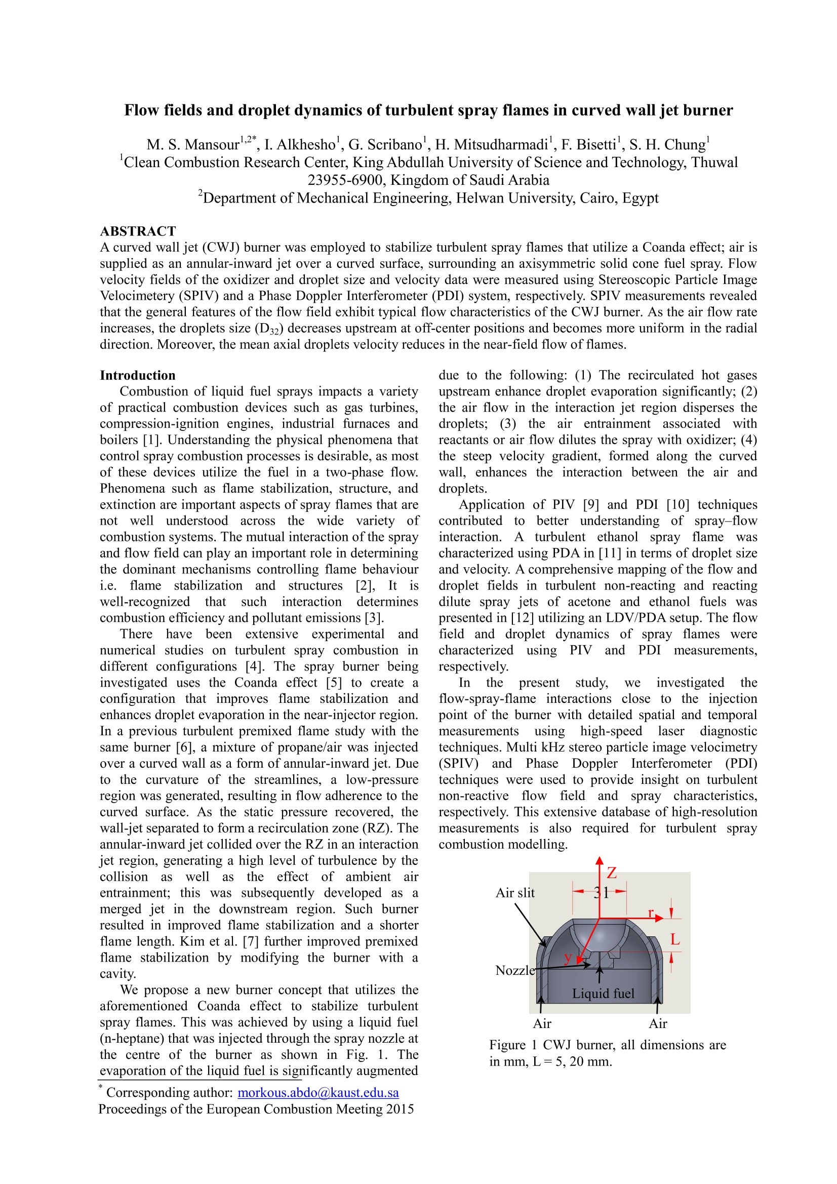
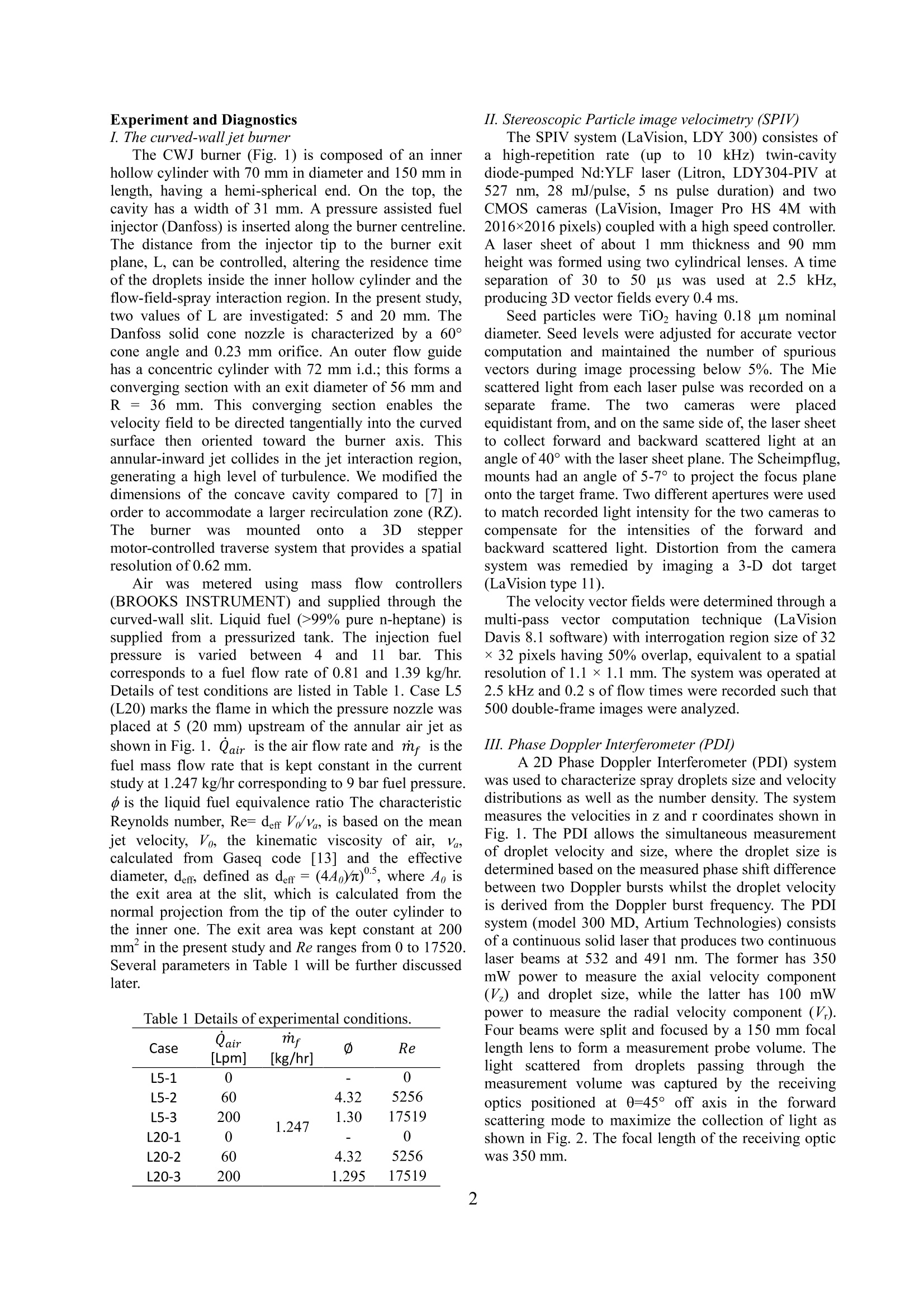
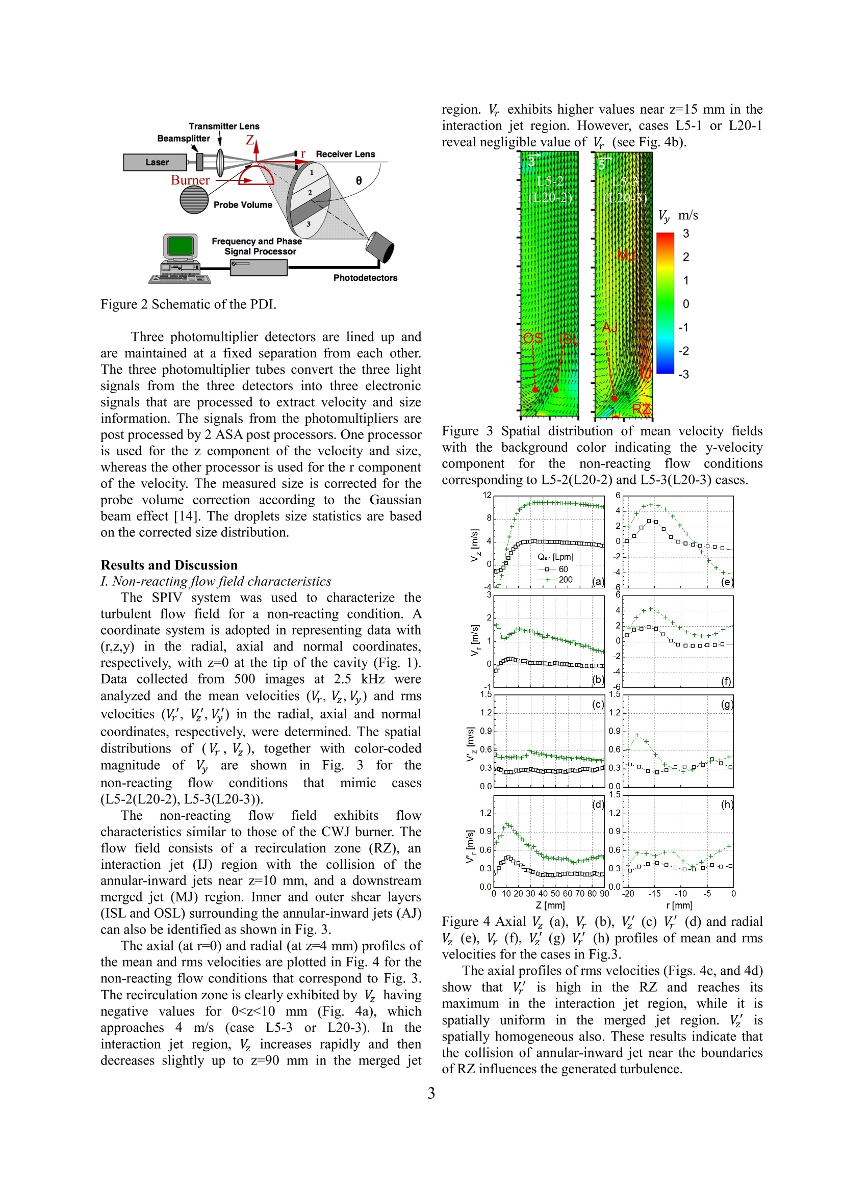
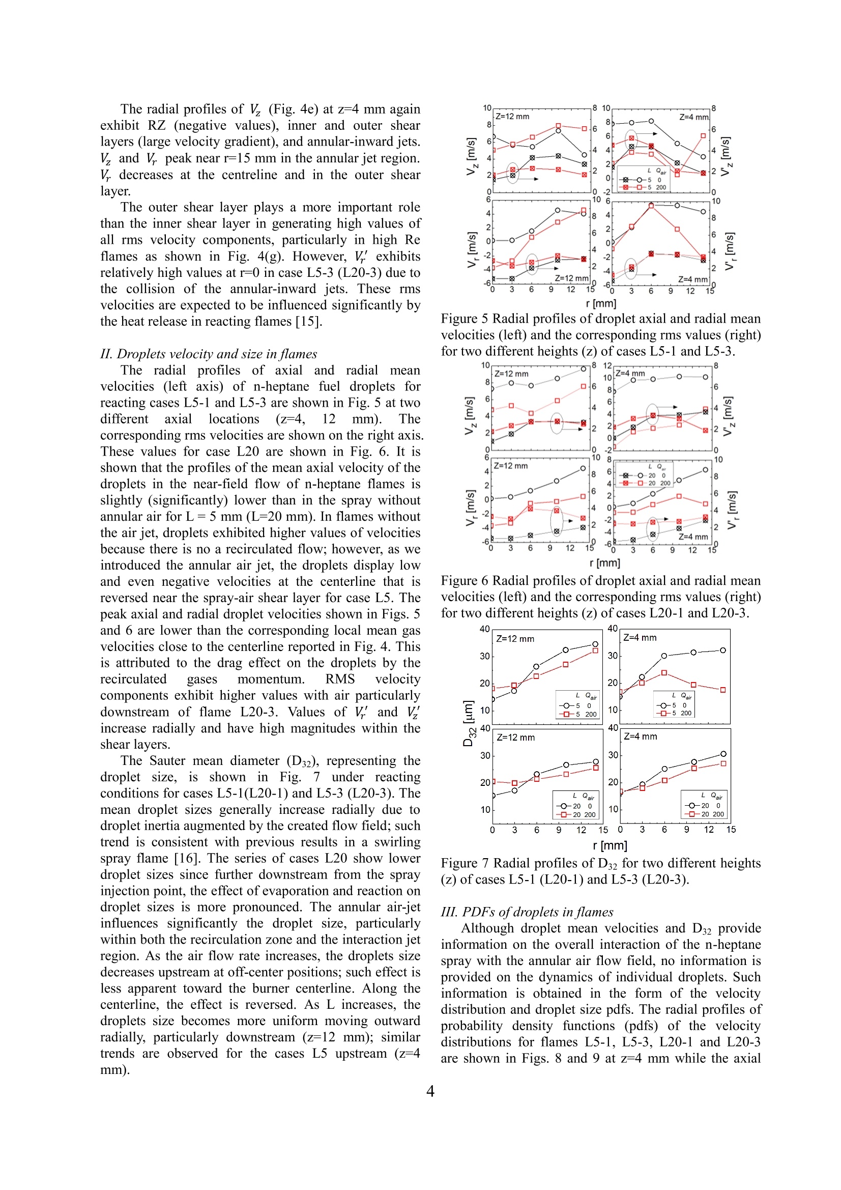
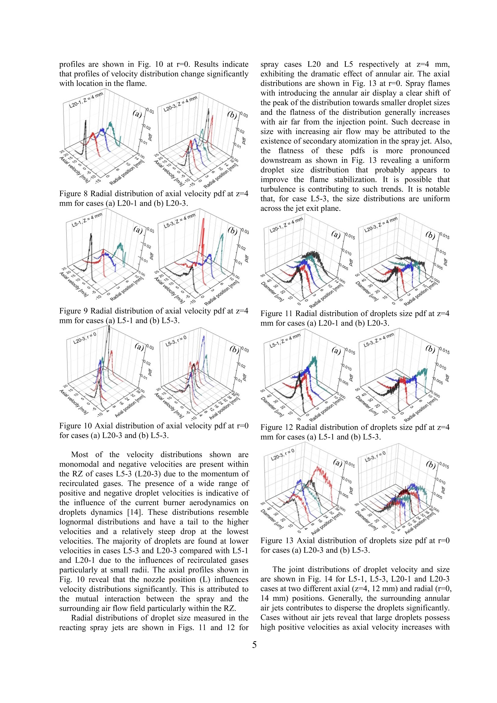
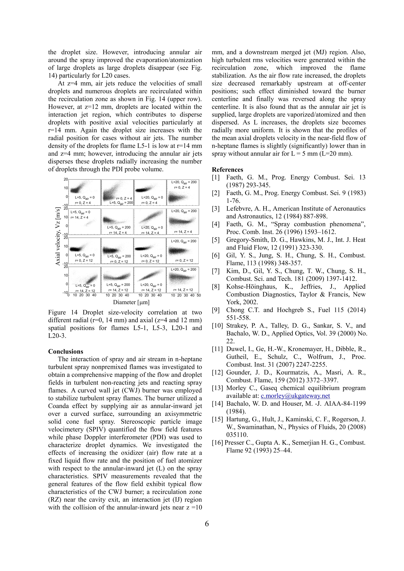
Flow fields and droplet dynamics of turbulent spray flames in curved wall jet burner M. S. Mansourl2*, I. Alkhesho', G. Scribano', H. Mitsudharmadi', F. Bisetti', S. H. Chung'Clean Combustion Research Center, King Abdullah University of Science and Technology, Thuwal23955-6900, Kingdom of Saudi Arabia Department ofMechanical Engineering, Helwan University, Cairo, Egypt ABSTRACT A curved wall jet (CWJ) burner was employed to stabilize turbulent spray flames that utilize a Coanda effect; air issupplied as an annular-inward jet over a curved surface, surrounding an axisymmetric solid cone fuel spray. Flowvelocity fields of the oxidizer and droplet size and velocity data were measured using Stereoscopic Particle ImageVelocimetery (SPIV) and a Phase Doppler Interferometer (PDI) system, respectively. SPIV measurements revealedthat the general features of the flow field exhibit typical flow characteristics of the CWJ burner. As the air flow rateincreases, the droplets size (D32) decreases upstream at off-center positions and becomes more uniform in the radialdirection. Moreover, the mean axial droplets velocity reduces in the near-field flow of flames. Introduction Combustion of liquid fuel sprays impacts a varietyof practical combustion devices such as gas turbines,compression-ignition engines, industrial furnaces andboilers [1]. Understanding the physical phenomena thatcontrol spray combustion processes is desirable, as mostof these devices utilize the fuel in a two-phase flow.Phenomena such as flame stabilization, structure, andextinction are important aspects of spray flames that arenotwellunderstood.aacrossthewideevariety ofcombustion systems. The mutual interaction of the sprayand flow field can play an important role in determiningthe dominant mechanisms controlling flame behaviouri.e.flameiestabilizationnand structures[2],It iswell-recognizedthat ssuch interactiondeterminescombustion efficiency and pollutant emissions [3]. Therehhavebeenextensiveeexperimentalandnumerical studies on turbulent spray combustion indifferent configurations [4]. The spray burner beinginvestigated uses the Coanda effect [5] to create aconfiguration that improves flame stabilization andenhances droplet evaporation in the near-injector region.In a previous turbulent premixed flame study with thesame burner [6], a mixture of propane/air was injectedover a curved wall as a form of annular-inward jet. Dueto the curvature of the streamlines, a low-pressureregion was generated, resulting in flow adherence to thecurved surface. As the static pressure recovered, thewall-jet separated to form a recirculation zone (RZ). Theannular-inward jet collided over the RZ in an interactionjet region, generating a high level of turbulence by thecollisionaswell astlthe effect of ambient airentrainment; this was subsequently developed as amerged jet in the downstream region. Such burnerresulted in improved flame stabilization and a shorterflame length. Kim et al. [7] further improved premixedflame stabilization by modifying the burner with acavity. We propose a new burner concept that utilizes theaforementioned Coanda effect to stabilize turbulentspray flames. This was achieved by using a liquid fuel(n-heptane) that was injected through the spray nozzle atthe centre of the burner as shown in Fig. 1. Theevaporation of the liquid fuel is significantly augmented ( Corresponding author: mo rkous.abdo@kaust.edu.sa Proceedings of the European Combustion Meeting 2015 ) due to the following: (1) The recirculated hot gasesupstream enhance droplet evaporation significantly; (2)the air flow in the interaction jet region disperses thedroplets; (3) theairr entrainment associatedl withreactants or air flow dilutes the spray with oxidizer; (4)the steep velocity gradient, formed along the curvedwall, enhances the interaction between the air anddroplets. Application of PIV [9] and PDI [10] techniquescontributeddtetobettaerr understandingg ooff sspray-flowinteraction. Aturbulent ethanolspray flamee wascharacterized using PDA in [11] in terms of droplet sizeand velocity. A comprehensive mapping of the flow anddroplet fields in turbulent non-reacting and reactingdilute spray jets of acetone and ethanol fuels waspresented in [12] utilizing an LDV/PDA setup. The flowfield and droplet dynamics of spray flameswerecharacterized using PIV andPDI measurements.respectively. In the present study,we investigatedd ttheflow-spray-flame interactions close to the injectionpoint of the burner with detailed spatial and temporalmeasurements using high-speed 1laser diagnostictechniques. Multi kHz stereo particle image velocimetry(SPIV)and PhaseeDopplerInterferometer(PDI)techniques were used to provide insight on turbulentnon-reactiveflowfield andspray characteristics,respectively. This extensive database of high-resolutionmeasurements is also required for turbulent spraycombustion modelling. Figure 1 CWJ burner, all dimensions arein mm,L=5,20 mm. Experiment and Diagnostics I. The curved-wall jet burne'rr The CWJ burner (Fig. 1) is composed of an innerhollow cylinder with 70 mm in diameter and 150 mm inlength, having a hemi-spherical end. On the top, thecavity has a width of 31 mm. A pressure assisted fuelinjector (Danfoss) is inserted along the burner centreline.The distance from the injector tip to the burner exitplane, L, can be controlled, altering the residence timeof the droplets inside the inner hollow cylinder and theflow-field-spray interaction region. In the present study,two values of L are investigated: 5 and 20 mm. TheDanfoss solid cone nozzle is characterized by a 60°cone angle and 0.23 mm orifice. An outer flow guidehas a concentric cylinder with 72 mm i.d.; this forms aconverging section with an exit diameter of 56 mm andR= 36 mm. This converging section enables thevelocity field to be directed tangentially into the curvedsurface then oriented toward the burner axis. Thisannular-inward jet collides in the jet interaction region,generating a high level of turbulence. We modified thedimensions of the concave cavity compared to [7] inorder to accommodate a larger recirculation zone (RZ).The burner Was mounted onto a 3D steppermotor-controlled traverse system that provides a spatialresolution of 0.62 mm. Airr wasmetered using mass flow controllers(BROOKS INSTRUMENT) and supplied through thecurved-wall slit. Liquid fuel (>99% pure n-heptane) issupplied from a pressurized tank. The injection fuelpressureisvaried between4and11 bar. Thiscorresponds to a fuel flow rate of 0.81 and 1.39 kg/hr.Details of test conditions are listed in Table 1. Case L5(L20) marks the flame in which the pressure nozzle wasplaced at 5 (20 mm) upstream of the annular air jet asshown in Fig. 1. Qair is the air flow rate and me is thefuel mass flow rate that is kept constant in the currentstudy at 1.247 kg/hr corresponding to 9 bar fuel pressure.is the liquid fuel equivalence ratio The characteristicReynolds number, Re= deff Vo/va, is based on the meanjet velocity, Vo, the kinematic viscosity of air, Vacalculated from Gaseq code [13] and the effectivediameter, der, defined as deff=(4A ))0.5, where Ao isthe exit area at the slit, which is calculated from thenormal projection from the tip of the outer cylinder tothe inner one. The exit area was kept constant at 200mmin the present study and Re ranges from 0 to 17520.Several parameters in Table 1 will be further discussedlater. Table 1 Details of experimental conditions. Case Qair [Lpm] m [kg/hr] 0 Re L5-1 0 0 L5-2 60 4.32 5256 L5-3 200 1.30 17519 L20-1 1.247 0 L20-2 4.32 5256 L20-3 200 1.295 17519 II. Stereoscopic Particle image velocimetry (SPIV) The SPIV system (LaVision, LDY 300) consistes ofa high-repetition rate (up to10 kHz) twin-cavitydiode-pumped Nd:YLF laser (Litron, LDY304-PIV at527 nm, 28 mJ/pulse, 5 ns pulse duration) and twoCMOS cameras (LaVision, Imager Pro HS 4M with2016×2016 pixels) coupled with a high speed controller.A laser sheet of about 1 mm thickness and 90 mmheight was formed using two cylindrical lenses. A timeseparation of 30 to 50 us wassiused at2.5 kHz.producing 3D vector fields every 0.4 ms. Seed particles were TiO2 having 0.18 um nominaldiameter. Seed levels were adjusted for accurate vectorcomputation and maintained the number of spuriousvectors during image processing below 5%. The Miescattered light from each laser pulse was recorded on aseparateeframe.The two cameras wereplacedequidistant from, and on the same side of, the laser sheetto collect forward and backward scattered light at anangle of 40° with the laser sheet plane. The Scheimpflug,mounts had an angle of 5-7° to project the focus planeonto the target frame. Two different apertures were usedto match recorded light intensity for the two cameras tocompensate for the intensities of the forward andbackward scattered light. Distortion from the camerasystem was remedied by imaging a 3-D dot target(LaVision type 11). The velocity vector fields were determined through amulti-pass vector computation technique (LaVisionDavis 8.1 software) with interrogation region size of 32x 32 pixels having 50% overlap, equivalent to a spatialresolution of 1.1 ×1.1 mm. The system was operated at2.5 kHz and 0.2 s of flow times were recorded such that500 double-frame images were analyzed. III. Phase Doppler Interferometer (PDI) A 2D Phase Doppler Interferometer (PDI) systemwas used to characterize spray droplets size and velocitydistributions as well as the number density. The systemmeasures the velocities in z and r coordinates shown inFig. 1. The PDI allows the simultaneous measurementof droplet velocity and size, where the droplet size isdetermined based on the measured phase shift differencebetween two Doppler bursts whilst the droplet velocityis derived from the Doppler burst frequency. The PDIsystem (model 300 MD, Artium Technologies) consistsof a continuous solid laser that produces two continuouslaser beams at 532 and 491 nm. The former has 350mW power to measure the axial velocity component(V) and droplet size, while the latter has 100 mWpower to measure the radial velocity component (Vh).Four beams were split and focused by a 150 mm focallength lens to form a measurement probe volume. Thelight scattered from dropletssipassing through themeasurement volume was captured by the receivingoptics positioned at 0=45° off axis in the forwardscattering mode to maximize the collection of light asshown in Fig. 2. The focal length of the receiving opticwas 350 mm. Figure2 Schematic ofthe PDI. Three photomultiplier detectors are lined up andare maintained at a fixed separation from each other.The three photomultiplier tubes convert the three lightsignals from the three detectors into three electronicsignals that are processed to extract velocity and sizeinformation. The signals from the photomultipliers arepost processed by 2 ASA post processors. One processoris used for the z component of the velocity and size,whereas the other processor is used for the r componentof the velocity. The measured size is corrected for theprobe volume correction according to the Gaussianbeam effect [14]. The droplets size statistics are basedon the corrected size distribution. Results and Discussion I. Non-reacting flow field characteristics The SPIV system was used to characterize theturbulent flow field for a non-reacting condition. Acoordinate system is adopted in representing data with(r,z,y) in the radial, axial and normal coordinates,respectively, with z=0 at the tip of the cavity (Fig. 1).Data collected from 500 images at 2.5 kHz wereanalyzed and the mean velocities (V.V,V) and rmsvelocities (V,) in the radial, axial and normalcoordinates,respectively, were determined. The spatialdistributions of (V,), together with color-codedmagnitudee of V,yareSshownin Fig.3for thenon-reactingflowconditions that mimic cases(L5-2(L20-2),L5-3(L20-3)). The non-reactingflow field exhibits flowcharacteristics similar to those of the CWJ burner. Theflow field consists of a recirculation zone (RZ), aninteraction jet (IJ) region with the collision of theannular-inward jets near z=10 mm, and a downstreammerged jet (MJ) region. Inner and outer shear layers(ISL and OSL) surrounding the annular-inward jets (AJ)can also be identified as shown in Fig. 3. The axial (at r=0) and radial (at z=4 mm) profiles ofthe mean and rms velocities are plotted in Fig. 4 for thenon-reacting flow conditions that correspond to Fig. 3.The recirculation zone is clearly exhibited by havingnegative values for 0
确定
还剩4页未读,是否继续阅读?

产品配置单


北京欧兰科技发展有限公司为您提供《曲面内壁喷嘴燃烧器中湍流喷雾火焰流场和液滴动力学检测方案(激光干涉仪)》,该方案主要用于其他中湍流喷雾火焰流场和液滴动力学检测,参考标准--,《曲面内壁喷嘴燃烧器中湍流喷雾火焰流场和液滴动力学检测方案(激光干涉仪)》用到的仪器有激光相位多普勒干涉仪LDV,PDI,PDPA,PDA、德国LaVision PIV/PLIF粒子成像测速场仪
推荐专场


相关方案
更多
该厂商其他方案
更多