


方案详情
文
超级电容的应用越来越重要。本文使用电化学技术对改进超级电容的性能进行了系统研究。
关键词:
Activated carbon; Intercalation; Electrochemical properties
方案详情

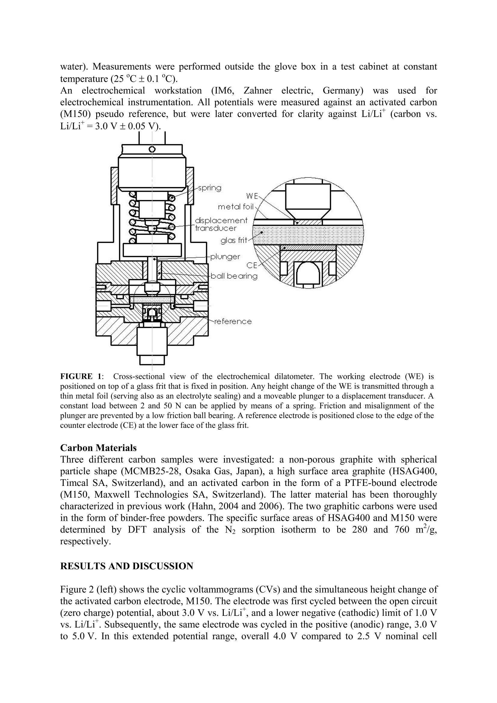
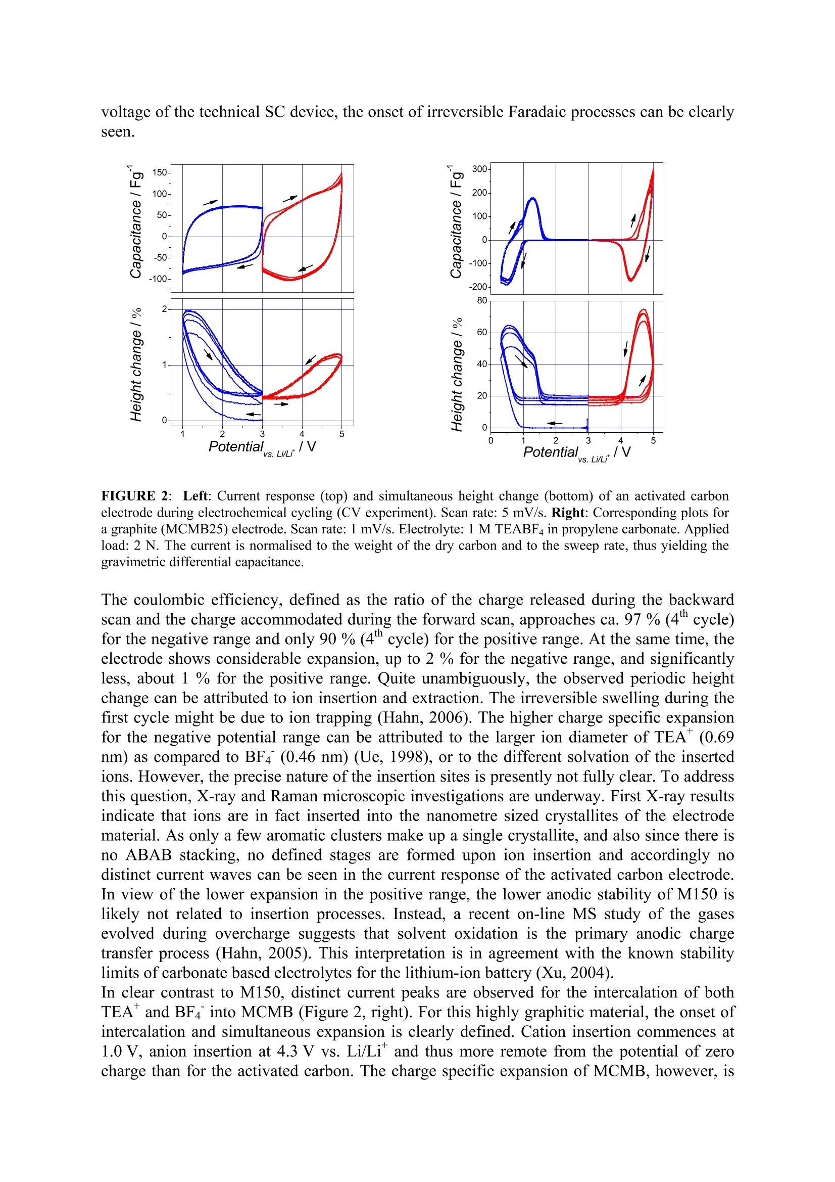
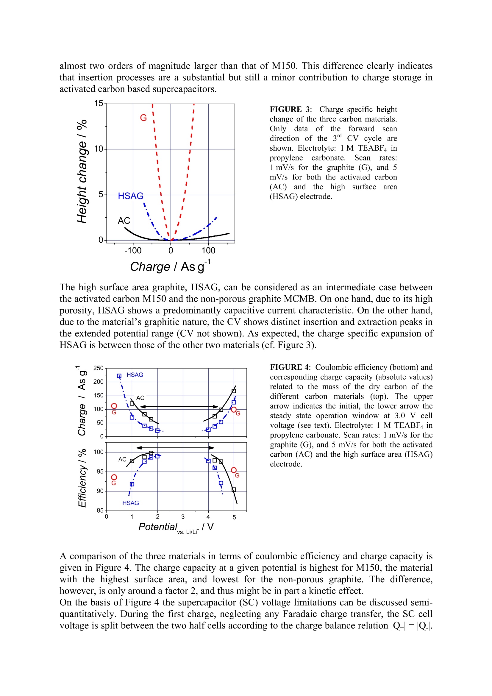
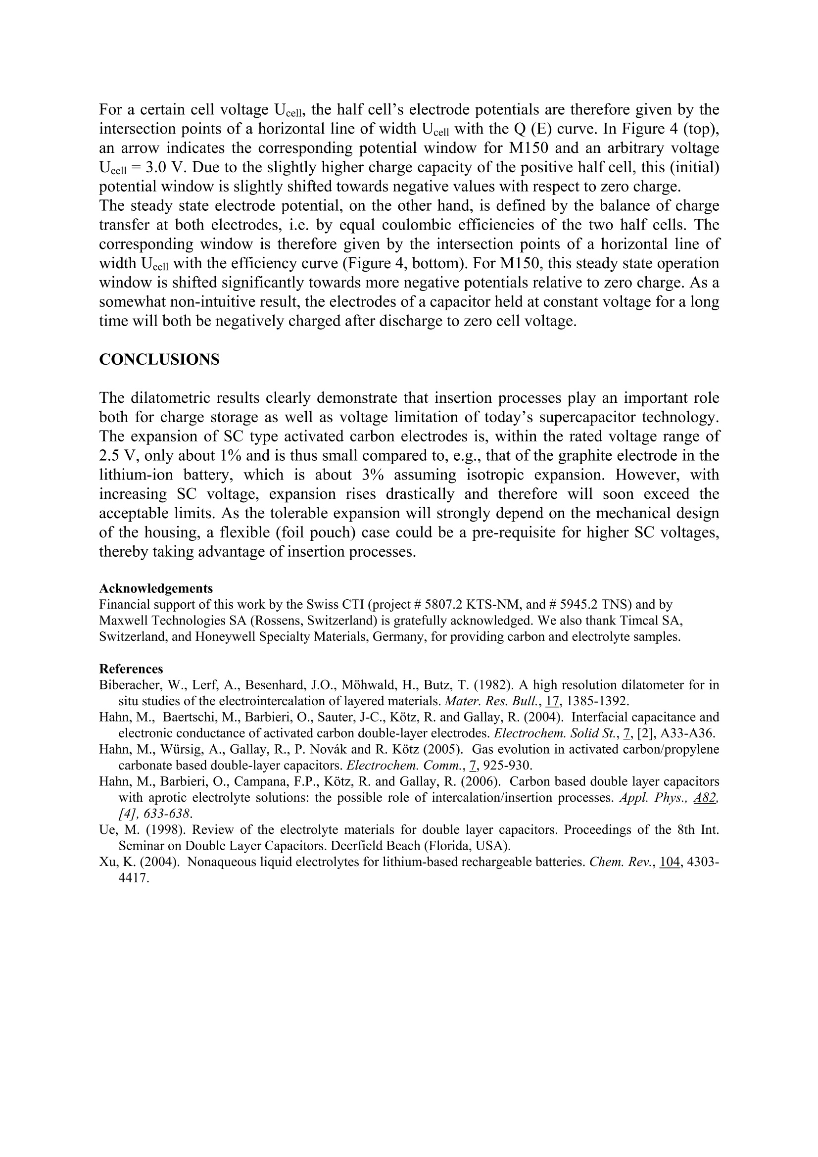
Activated carbons for supercapacitors.The impact ofcharge-induced strain on life time and performance issues. Matthias Hahn , Patrick Ruch , Olivier Barbieri, Annette Foelske,Riidiger Kotz,Roland Gallay Paul Scherrer Institut, Electrochemistry Laboratory, 5232 Villigen PSI, SwitzerlandMaxwell Technologies SA, CH-1728 Rossens, Switzerland Email: matthias.hahn@psi.ch Keywords Activated carbon; Intercalation; Electrochemical properties INTRODUCTION Charge storage in supercapacitors (SC) is commonly assumed to take place in high surfacearea electrodes at the large inner boundary between electronic and ionic conductor(electrolyte) by means of electrostatic charge separation. According to this picture, the energyis only stored in the electric field and no chemical or structural changes occur duringcharging/discharging.Therefore, unlike batteries, no mechanical fatigue leading tcapacitance fade is thought to occur, thereby accounting for the almost unlimited SC cyclelife. Although this concept appears intuitively convincing, it is likely to be too simplistic. Infact, we could recently show by electrochemical dilatometry that insertion processes similarto those occurring in lithium-ion batttteer1r6ies take place in SCs based on activated carbons andaprotic, organic electrolytes (Hahn, 2006). In the present contribution we show that theseprocesses contribute substantially to charge storage already well within the usual SCoperation range. It is also demonstrated that the significantly lower device voltage of SCs,below 3.0 V compared to above 4.0 V for lithium-ion batteries, is mainly due to the lowerstability of the SC electrodes against ion insertion. EXPERIMENTAL Electrochemical Dilatometry The electrochemical measurements were carried out with a home-made dilatometer (Figure1) which is an update of a previous construction (Hahn, 2006). Basically, the dilatometerconsists of two electrodes separated by a stiff glass frit (24 mm in diameter, 4 mm thick,porosity 1) fixed in position. A 20 um thick and polyimide reinforced aluminium foil ispositioned on top of the upper working electrode (WE). This metal foil has a manifoldfunction. It serves as the current collector as well as the electrolyte sealing, and it transmitsany height change of the WE via the moveable plunger to the displacement transducer(W5TK, Hottinger Baldwin Messtechnik, Germany). Free-standing electrodes (5 to 10 mm indiameter) as well as binder-free powders can be used as the WE material. In the latter case, asmall amount of the powder (ca. 5 mg) was pressed into a pellet-like geometry (about 5 mmin diameter, some 100 um thick) between the glass frit and the metal foil. After assembly inair, the dilatometer cell (with the displacement transducer detached) was dried for 24 h at120℃ and 0.01 mbar, then cooled down to ambient temperature in argon atmosphere,transferred to a glove box (argon,<10 ppm water) and finally filled there with the electrolytesolution, 1 M (C2H5)4NBF4 (TEABF4) in propylene carbonate (battery grade,<20 ppm water). Measurements were performed outside the glove box in a test cabinet at constanttemperature (25℃±0.1℃). Ann electrochemicalworkstation(IM6,Zahner electric, Germany)was used forelectrochemical instrumentation. All potentials were measured against an activated carbon(M150) pseudo reference, but were later converted for clarity against Li/Li (carbon vs.Li/Li*=3.0V±0.05V). FIGURE 1::Cross-sectional view of the electrochemical dilatometer. The working electrode (WE) ispositioned on top of a glass frit that is fixed in position. Any height change of the WE is transmitted through athin metal foil (serving also as an electrolyte sealing) and a moveable plunger to a displacement transducer. Aconstant load between 2 and 50 N can be applied by means of a spring. Friction and misalignment of theplunger are prevented by a low friction ball bearing. A reference electrode is positioned close to the edge of thecounter electrode (CE) at the lower face of the glass frit. Carbon Materials Three different carbon samples were investigated: a non-porous graphite with sphericalparticle shape (MCMB25-28, Osaka Gas, Japan), a high surface area graphite (HSAG400,Timcal SA, Switzerland), and an activated carbon in the form of a PTFE-bound electrode(M150, Maxwell Technologies SA, Switzerland). The latter material has been thoroughlycharacterized in previous work (Hahn, 2004 and 2006). The two graphitic carbons were usedin the form of binder-free powders. The specific surface areas of HSAG400 and M150 weredetermined by DFT analysis of the N2 sorption isotherm to be 280 and 760 m /g,respectively. RESULTS AND DISCUSSION Figure 2 (left) shows the cyclic voltammograms (CVs) and the simultaneous height change ofthe activated carbon electrode, M150. The electrode was first cycled between the open circuit(zero charge) potential, about 3.0 V vs. Li/Li, and a lower negative (cathodic) limit of 1.0 Vvs. Li/Li . Subsequently, the same electrode was cycled in the positive (anodic) range, 3.0 Vto 5.0 V. In this extended potential range, overall 4.0 V compared to 2.5 V nominal cell voltage of the technical SC device, the onset of irreversible Faradaic processes can be clearlyseen. FIGURE 2:Left: Current response (top) and simultaneous height change (bottom) of an activated carbonelectrode during electrochemical cycling (CV experiment). Scan rate: 5 mV/s. Right: Corresponding plots fora graphite (MCMB25)electrode. Scan rate: 1 mV/s. Electrolyte: 1 MTEABF4 in propylene carbonate. Appliedload:2 N. The current is normalised to the weight of the dry carbon and to the sweep rate, thus yielding thegravimetric differential capacitance. The coulombic efficiency, defined as the ratio of the charge released during the backwardscan and the charge accommodated during the forward scan, approaches ca. 97 % (4" cycle)for the negative range and only 90% (4" cycle) for the positive range. At the same time, theelectrode shows considerable expansion, up to 2 % for the negative range, and significantlyless, about 1 % for the positive range. Quite unambiguously, the observed periodic heightchange can be attributed to ion insertion and extraction. The irreversible swelling during thefirst cycle might be due to ion trapping (Hahn, 2006). The higher charge specific expansionfor the negative potential range can be attributed to the larger ion diameter of TEA*(0.69nm) as compared to BF4 (0.46 nm) (Ue, 1998), or to the different solvation of the insertedions. However, the precise nature of the insertion sites is presently not fully clear. To addressthis question, X-ray and Raman microscopic investigations are underway. First X-ray resultsindicate that ions are in fact inserted into the nanometre sized crystallites of the electrodematerial. As only a few aromatic clusters make up a single crystallite, and also since there isno ABAB stacking, no defined stages are formed upon ion insertion and accordingly nodistinct current waves can be seen in the current response of the activated carbon electrode.In view of the lower expansion in the positive range, the lower anodic stability of M150 islikely not related to insertion processes. Instead, a recent on-line MS study of the gasesevolved during overcharge suggests that solvent oxidation is the primary anodic chargetransfer process (Hahn, 2005). This interpretation is in agreement with the known stabilitylimits of carbonate based electrolytes for the lithium-ion battery (Xu, 2004).In clear contrast to M150, distinct current peaks are observed for the intercalation of both TEA and BF4 into MCMB (Figure 2, right). For this highly graphitic material, the onset ofintercalation and simultaneous expansion is clearly defined. Cation insertion commences at1.0 V, anion insertion at 4.3 V vs. Li/Li and thus more remote from the potential of zerocharge than for the activated carbon. The charge specific expansion of MCMB, however, is almost two orders of magnitude larger than that of M150. This difference clearly indicatesthat insertion processes are a substantial but still a minor contribution to charge storage inactivated carbon based supercapacitors. FIGURE 3: Charge specific heightchange of the three carbon materials.Only data of theIforwardscandirection of the 3d CV cycle areshown. Electrolyte: 1M TEABF4 inpropylene carbonate. Scanrates:1 mV/s for the graphite (G), and 5mV/s for both the activated carbon(AC) and the highhSsurfaceearea(HSAG) electrode. Charge/ Asg The high surface area graphite, HSAG, can be considered as an intermediate case betweenthe activated carbon M150 and the non-porous graphite MCMB. On one hand, due to its highporosity, HSAG shows a predominantly capacitive current characteristic. On the other hand,due to the material's graphitic nature, the CV shows distinct insertion and extraction peaks inthe extended potential range (CV not shown). As expected, the charge specific expansion ofHSAG is between those of the other two materials (cf. Figure 3). FIGURE 4: Coulombic efficiency (bottom) andcorresponding charge capacity (absolute values)related to the mass of the dry carbon of thedifferent carbon materials (top). The upperarrow indicates the initial, the lower arrow thesteady state operation window at 3.0 V cellvoltage (see text). Electrolyte:1 M TEABF4 inpropylene carbonate. Scan rates: 1mV/s for thegraphite (G), and 5 mV/s for both the activatedcarbon (AC) and the high surface area (HSAG)electrode. A comparison of the three materials in terms of coulombic efficiency and charge capacity isgiven in Figure 4. The charge capacity at a given potential is highest for M150, the materialwith the highest surface area, and lowest for the non-porous graphite. The difference,however,is only around a factor 2, and thus might be in part a kinetic effect. On the basis of Figure 4 the supercapacitor (SC) voltage limitations can be discussed semi-quantitatively. During the first charge, neglecting any Faradaic charge transfer, the SC cellvoltage is split between the two half cells according to the charge balance relation |Q+|=|Q.|. For a certain cell voltage Ucell, the half cell's electrode potentials are therefore given by theintersection points of a horizontal line of width Ucell with the Q(E) curve. In Figure 4 (top),an arrow indicates the corresponding potential window for M150 and an arbitrary voltageUcell=3.0 V. Due to the slightly higher charge capacity of the positive half cell, this (initial)potential window is slightly shifted towards negative values with respect to zero charge. The steady state electrode potential, on the other hand, is defined by the balance of chargetransfer at both electrodes, i.e. by equal coulombic efficiencies of the two half cells. Thecorresponding window is therefore given by the intersection points of a horizontal line ofwidth Ucell with the efficiency curve (Figure 4, bottom). For M150, this steady state operationwindow is shifted significantly towards more negative potentials relative to zero charge. As asomewhat non-intuitive result, the electrodes of a capacitor held at constant voltage for a longtime will both be negatively charged after discharge to zero cell voltage. CONCLUSIONS The dilatometric results clearly demonstrate that insertion processes play an important roleboth for charge storage as well as voltage limitation of today's supercapacitor technology.The expansion of SC type activated carbon electrodes is, within the rated voltage range of2.5 V, only about 1% and is thus small compared to, e.g., that of the graphite electrode in thelithium-ion battery, which is about 3% assuming isotropic expansion. However, withincreasing SC voltage, expansion rises drastically and therefore will soon exceed theacceptable limits. As the tolerable expansion will strongly depend on the mechanical designof the housing, a flexible (foil pouch) case could be a pre-requisite for higher SC voltages,thereby taking advantage of insertion processes. Acknowledgements Financial support of this work by the Swiss CTI (project # 5807.2 KTS-NM, and # 5945.2 TNS) and byMaxwell Technologies SA (Rossens, Switzerland) is gratefully acknowledged. We also thank Timcal SA,Switzerland, and Honeywell Specialty Materials, Germany, for providing carbon and electrolyte samples. References ( Biberacher, W ., Lerf, A., Besenhard, J.O., Mohwald, H.,Butz, T. (198 2 ). A high resolution dilatometer for in situ studies of the electrointercalation o f layered materials. Mater. Res. Bull, 17, 1385-1392. ) ( Hahn, M., B a ertschi, M., Barbieri,O., Sauter, J-C.,Kotz, R. a n d Gallay, R. (2004 ) . Interf a cial capacitance andelectronic conductance of a ctivated carbon double-layer electrodes.Electrochem. Solid St., Z , [2],A33-A36. ) Hahn, M., Wursig, A., Gallay, R., P. Novak and R. Kotz (2005). Gas evolution in activated carbon/propylenecarbonate based double-layer capacitors. Electrochem. Comm.,Z,925-930. ( Hahn, M ., B arbieri, O., Campana, F.P., Kotz, R. and Gallay, R. (2006). Carbon based double layer capacitorswith aprotic e l ectrolyte solutions: th e possible rol e of inte r calation/insertion processes. Appl. Phys., 482,[4],633-638. ) ( Ue, M. (1998). Review of the el e ctrolyte m a terials for double l a yer capacitors. P roceedings of the 8th Int.Seminar on D ouble Layer Capacitors. Deerfield Beach (Florida,USA). ) ( Xu, K.(2004). No n aqueous liqui d electrolytes for l ithium-based rechargeable batteries. Chem. Rev., 104, 4303- 4417. )
确定
还剩3页未读,是否继续阅读?

香港环球分析测试仪器有限公司为您提供《超级电容中性能研究检测方案(电化学工作站)》,该方案主要用于其他中电化学性能检测,参考标准--,《超级电容中性能研究检测方案(电化学工作站)》用到的仪器有
相关方案
更多