


采用LaVision公司的增强型CCD相机对火焰喷射对象进行了测量。研究了喷嘴直径对火焰举升长度的影响。
方案详情

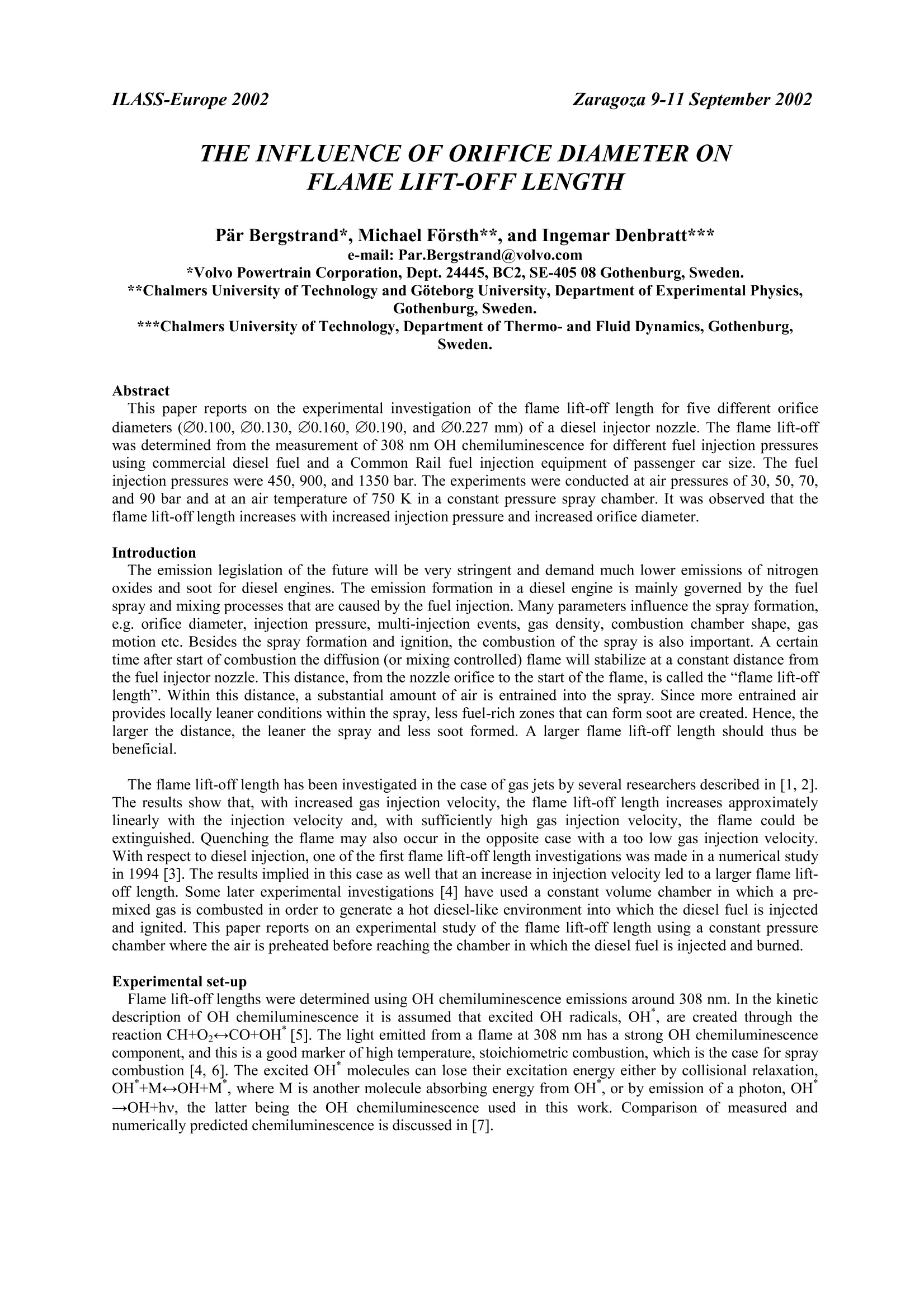
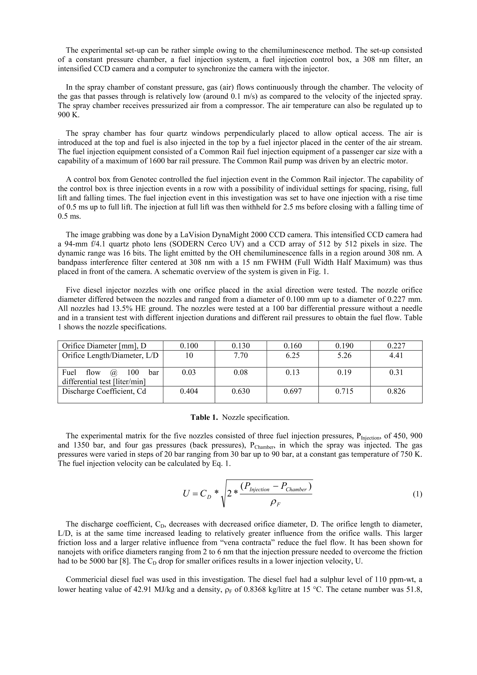
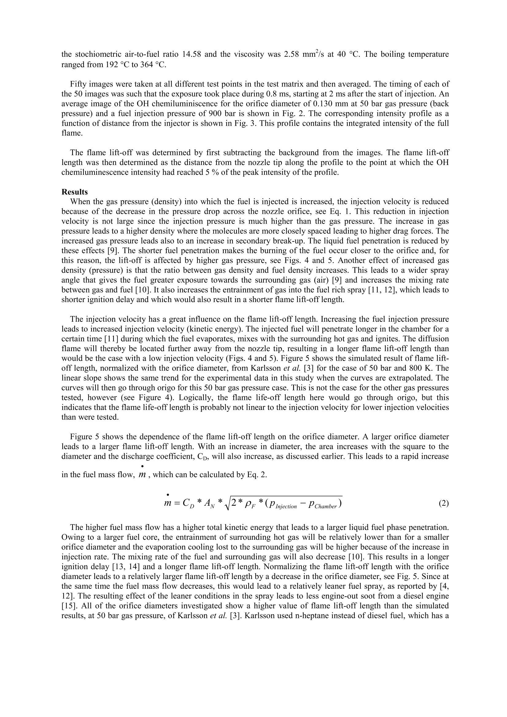
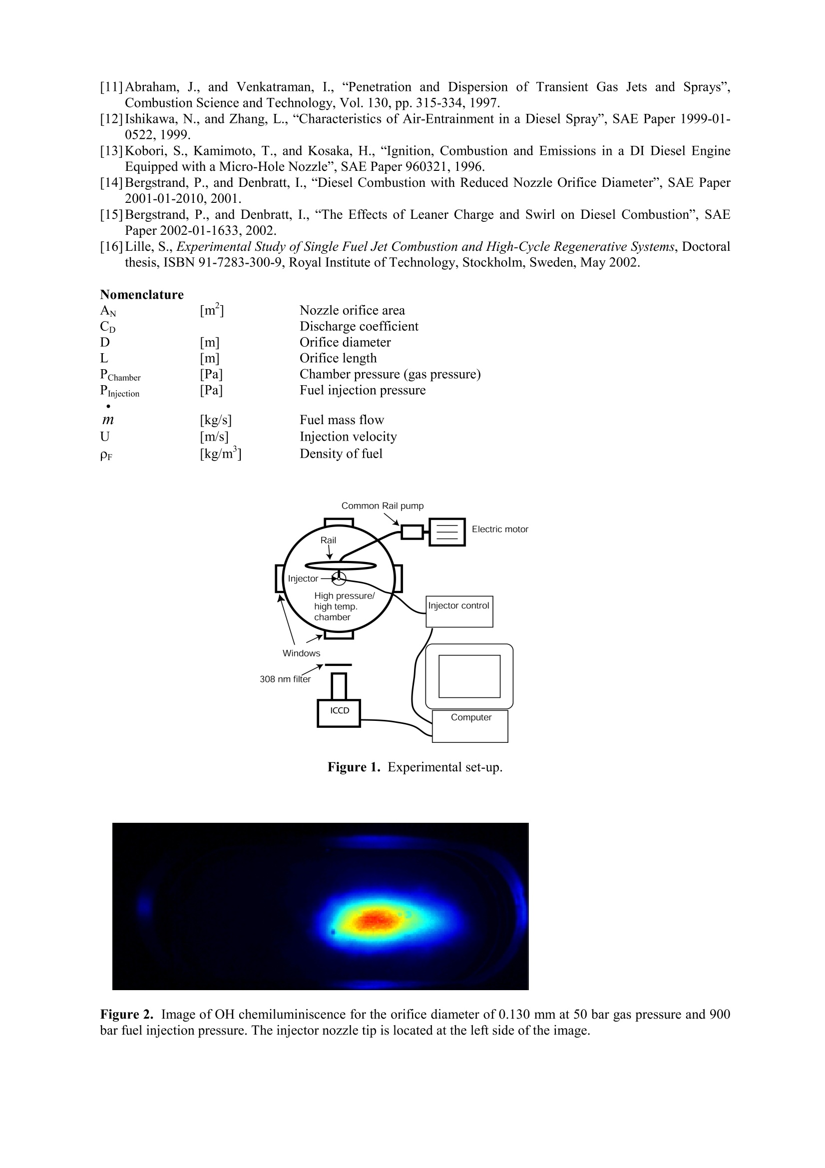
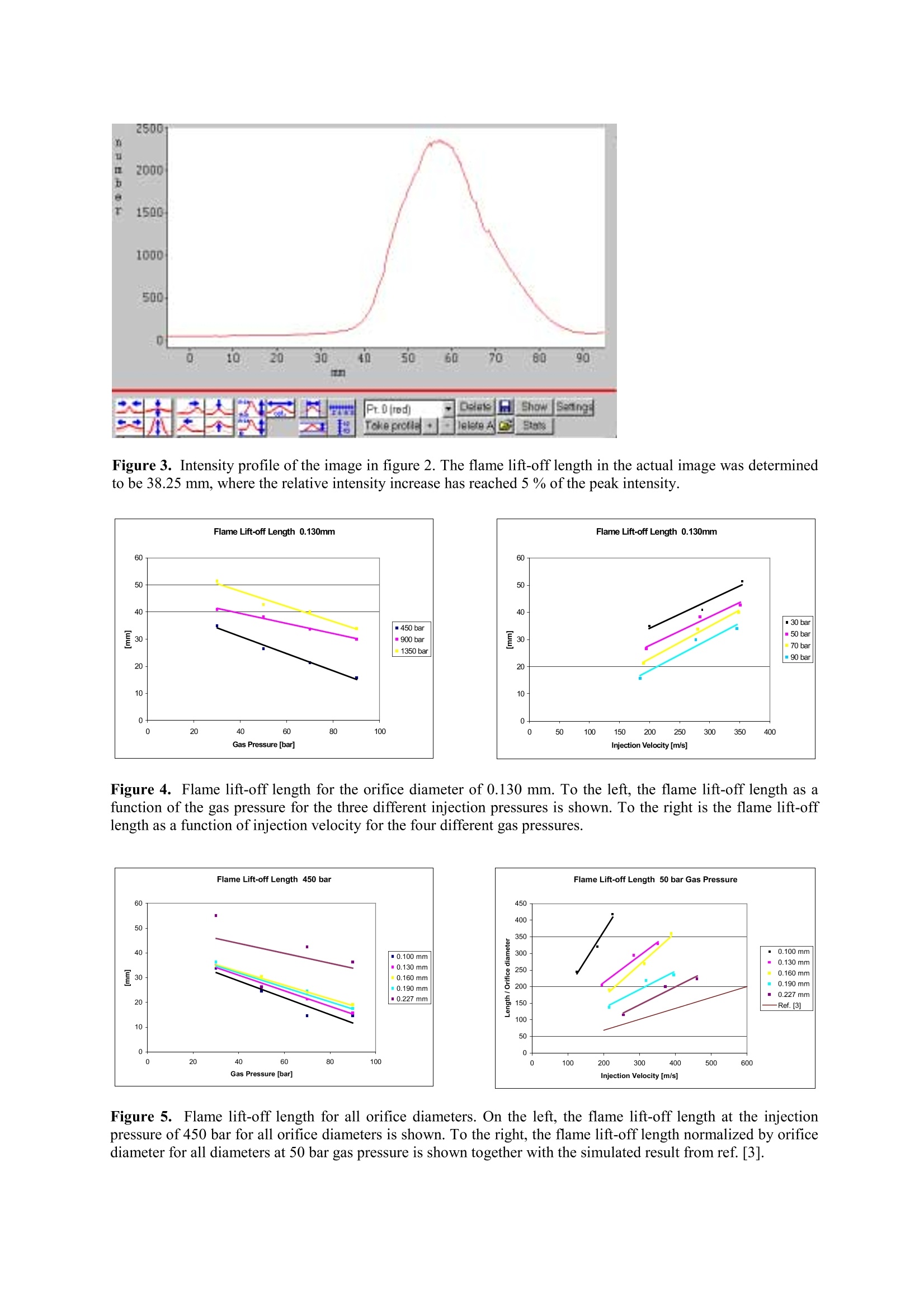
Zaragoza 9-11 September 2002ILASS-Europe 2002 THE INFLUENCE OF ORIFICE DIAMETERONFLAME LIFT-OFFLENGTH Par Bergstrand*,Michael Forsth**, and Ingemar Denbratt*** e-mail: Par.Bergstrand@volvo.com *Volvo Powertrain Corporation, Dept. 24445, BC2, SE-405 08 Gothenburg, Sweden.**Chalmers University of Technology and Goteborg University, Department of Experimena cs. Gothenburg, Sweden. ***Chalmers University of Technology, Department of Thermo- and Fluid Dynamics, Gothenburg,Sweden. Abstract This paper reports on the experimental investigation of the flame lift-off length for five different orificediameters (00.100,00.130,00.160,00.190, and 00.227 mm) of a diesel injector nozzle. The flame lift-offwas determined from the measurement of 308 nm OH chemiluminescence for different fuel injection pressuresusing commercial diesel fuel and a Common Rail fuel injection equipment of passenger car size. The fuelinjection pressures were 450, 900, and 1350 bar. The experiments were conducted at air pressures of 30, 50, 70,and 90 bar and at an air temperature of 750 K in a constant pressure spray chamber. It was observed that theflame lift-off length increases with increased injection pressure and increased orifice diameter. Introduction The emission legislation of the future will be very stringent and demand much lower emissions of nitrogenoxides and soot for diesel engines. The emission formation in a diesel engine is mainly governed by the fuelspray and mixing processes that are caused by the fuel injection. Many parameters influence the spray formation,e.g. orifice diameter, injection pressure, multi-injection events, gas density, combustion chamber shape, gasmotion etc. Besides the spray formation and ignition, the combustion of the spray is also important. A certaintime after start of combustion the diffusion (or mixing controlled) flame will stabilize at a constant distance fromthe fuel injector nozzle. This distance, from the nozzle orifice to the start of the flame, is called the “flame lift-offlength". Within this distance, a substantial amount of air is entrained into the spray. Since more entrained airprovides locally leaner conditions within the spray, less fuel-rich zones that can form soot are created. Hence, thelarger the distance, the leaner the spray and less soot formed. A larger flame lift-off length should thus bebeneficial. The flame lift-offlength has been investigated in the case of gas jets by several researchers described in [1,2].The results show that, with increased gas injection velocity, the flame lift-off length increases approximatelylinearly with the injection velocity and, with sufficiently high gas injection velocity, the flame could beextinguished. Quenching the flame may also occur in the opposite case with a too low gas injection velocity.With respect to diesel injection, one of the first flame lift-off length investigations was made in a numerical studyin 1994 [3]. The results implied in this case as well that an increase in injection velocity led to a larger flame lift-off length. Some later experimental investigations [4] have used a constant volume chamber in which a pre-mixed gas is combusted in order to generate a hot diesel-like environment into which the diesel fuel is injectedand ignited. This paper reports on an experimental study of the flame lift-off length using a constant pressurechamber where the air is preheated before reaching the chamber in which the diesel fuel is injected and burned. Experimental set-up Flame lift-off lengths were determined using OH chemiluminescence emissions around 308 nm. In the kineticdescription ofOH chemiluminescence it is assumed that excited OH radicals, OH, are created through thereaction CH+02→CO+OH"[5]. The light emitted from a flame at 308 nm has a strong OH chemiluminescencecomponent, and this is a good marker of high temperature, stoichiometric combustion, which is the case for spraycombustion [4, 6].The excited OH"molecules can lose their excitation energy either by collisional relaxation,OH+M→OH+M, where M is another molecule absorbing energy from OH", or by emission of a photon, OH"→OH+hv, the latter being the OH chemiluminescence used in this work. Comparison of measured andnumerically predicted chemiluminescence is discussed in [7]. The experimental set-up can be rather simple owing to the chemiluminescence method. The set-up consistedof a constant pressure chamber, a fuel injection system, a fuel injection control box, a 308 nm filter, anintensified CCD camera and a computer to synchronize the camera with the injector. In the spray chamber of constant pressure, gas (air) flows continuously through the chamber. The velocity ofthe gas that passes through is relatively low (around 0.1 m/s) as compared to the velocity of the injected spray.The spray chamber receives pressurized air from a compressor. The air temperature can also be regulated up to900 K. The spray chamber has four quartz windows perpendicularly placed to allow optical access. The air isintroduced at the top and fuel is also injected in the top by a fuel injector placed in the center of the air stream.The fuel injection equipment consisted of a Common Rail fuel injection equipment of a passenger car size with acapability of a maximum of 1600 bar rail pressure. The Common Rail pump was driven by an electric motor. A control box from Genotec controlled the fuel injection event in the Common Rail injector. The capability ofthe control box is three injection events in a row with a possibility of individual settings for spacing, rising, fulllift and falling times. The fuel injection event in this investigation was set to have one injection with a rise timeof 0.5 ms up to full lift. The injection at full lift was then withheld for 2.5 ms before closing with a falling time of0.5 ms. The image grabbing was done by a LaVision DynaMight 2000 CCD camera. This intensified CCD camera hada 94-mm f/4.1 quartz photo lens (SODERN Cerco UV) and a CCD array of 512 by 512 pixels in size. Thedynamic range was 16 bits. The light emitted by the OH chemiluminescence falls in a region around 308 nm. Abandpass interference filter centered at 308 nm with a 15 nm FWHM (Full Width Half Maximum) was thusplaced in front of the camera. A schematic overview of the system is given in Fig. 1. Five diesel injector nozzles with one orifice placed in the axial direction were tested. The nozzle orificediameter differed between the nozzles and ranged from a diameter of 0.100 mm up to a diameter of 0.227 mm.All nozzles had 13.5% HE ground. The nozzles were tested at a 100 bar differential pressure without a needleand in a transient test with different injection durations and different rail pressures to obtain the fuel flow. Table1 shows the nozzle specifications. Orifice Diameter [mml, D 0.100 0.130 0.160 0.190 0.227 Orifice Length/Diameter, L/D 10 7.70 6.25 5.26 4.41 Fuelflow @ 100 bardifferential test [liter/min1 0.03 0.08 0.13 0.19 0.31 Discharge Coefficient, Cd 0.404 0.630 0.697 0.715 0.826 Table 1. Nozzle specification. The experimental matrix for the five nozzles consisted of three fuel injection pressures, PInjection, of 450, 900and 1350 bar, and four gas pressures (back pressures), Pchamber, in which the spray was injected. The gaspressures were varied in steps of 20 bar ranging from 30 bar up to 90 bar, at a constant gas temperature of 750 K.The fuel injection velocity can be calculated by Eq. 1. The discharge coefficient, Cp, decreases with decreased orifice diameter, D. The orifice length to diameter,L/D, is at the same time increased leading to relatively greater influence from the orifice walls. This largerfriction loss and a larger relative influence from“vena contracta”reduce the fuel flow. It has been shown fornanojets with orifice diameters ranging from 2 to 6 nm that the injection pressure needed to overcome the frictionhad to be 5000 bar [8]. The Cp drop for smaller orifices results in a lower injection velocity, U. Commericial diesel fuel was used in this investigation. The diesel fuel had a sulphur level of 110 ppm-wt, alower heating value of 42.91 MJ/kg and a density, pr of 0.8368 kg/litre at 15 °C. The cetane number was 51.8, the stochiometric air-to-fuel ratio 14.58 and the viscosity was 2.58 mm /s at 40 ℃. The boiling temperatureranged from 192 °℃ to 364°C. Fifty images were taken at all different test points in the test matrix and then averaged. The timing of each ofthe 50 images was such that the exposure took place during 0.8 ms, starting at 2 ms after the start of injection. Anaverage image of the OH chemiluminiscence for the orifice diameter of 0.130 mm at 50 bar gas pressure (backpressure) and a fuel injection pressure of900 bar is shown in Fig. 2. The corresponding intensity profile as afunction of distance from the injector is shown in Fig. 3. This profile contains the integrated intensity of the fullflame. The flame lift-off was determined by first subtracting the background from the images. The flame lift-offlength was then determined as the distance from the nozzle tip along the profile to the point at which the OHchemiluminescence intensity had reached 5 % of the peak intensity of the profile. Results When the gas pressure (density) into which the fuel is injected is increased, the injection velocity is reducedbecause of the decrease in the pressure drop across the nozzle orifice, see Eq. 1. This reduction in injectionvelocity is not large since the injection pressure is much higher than the gas pressure. The increase in gaspressure leads to a higher density where the molecules are more closely spaced leading to higher drag forces. Theincreased gas pressure leads also to an increase in secondary break-up.The liquid fuel penetration is reduced bythese effects [9]. The shorter fuel penetration makes the burning of the fuel occur closer to the orifice and, forthis reason, the lift-off is affected by higher gas pressure, see Figs. 4 and 5. Another effect of increased gasdensity (pressure) is that the ratio between gas density and fuel density increases. This leads to a wider sprayangle that gives the fuel greater exposure towards the surrounding gas (air) [9] and increases the mixing ratebetween gas and fuel [10]. It also increases the entrainment of gas into the fuel rich spray [11, 12], which leads toshorter ignition delay and which would also result in a shorter flame lift-off length. The injection velocity has a great influence on the flame lift-off length. Increasing the fuel injection pressureleads to increased injection velocity (kinetic energy). The injected fuel will penetrate longer in the chamber for acertain time [11] during which the fuel evaporates, mixes with the surrounding hot gas and ignites. The diffusionflame will thereby be located further away from the nozzle tip, resulting in a longer flame lift-off length thanwould be the case with a low injection velocity (Figs. 4 and 5). Figure 5 shows the simulated result of flame lift-off length, normalized with the orifice diameter, from Karlsson et al. [3] for the case of 50 bar and 800 K. Thelinear slope shows the same trend for the experimental data in this study when the curves are extrapolated. Thecurves will then go through origo for this 50 bar gas pressure case. This is not the case for the other gas pressurestested, however (see Figure 4). Logically, the flame life-off length here would go through origo, but thisindicates that the flame life-off length is probably not linear to the injection velocity for lower injection velocitiesthan were tested. Figure 5 shows the dependence of the flame lift-off length on the orifice diameter. A larger orifice diameterleads to a larger flame lift-off length. With an increase in diameter, the area increases with the square to thediameter and the discharge coefficient, Cp, will also increase, as discussed earlier. This leads to a rapid increase in the fuel mass flow, m, which can be calculated by Eq. 2 The higher fuel mass flow has a higher total kinetic energy that leads to a larger liquid fuel phase penetration.Owing to a larger fuel core, the entrainment of surrounding hot gas will be relatively lower than for a smallerorifice diameter and the evaporation cooling lost to the surrounding gas will be higher because of the increase ininjection rate. The mixing rate of the fuel and surrounding gas will also decrease [10]. This results in a longerignition delay [13, 14] and a longer flame lift-off length. Normalizing the flame lift-off length with the orificediameter leads to a relatively larger flame lift-off length by a decrease in the orifice diameter, see Fig. 5. Since atthe same time the fuel mass flow decreases, this would lead to a relatively leaner fuel spray, as reported by [4,12]. The resulting effect of the leaner conditions in the spray leads to less engine-out soot from a diesel engine[15]. All of the orifice diameters investigated show a higher value of flame lift-off length than the simulatedresults, at 50 bar gas pressure, of Karlsson et al. [3]. Karlsson used n-heptane instead of diesel fuel, which has a similar cetane number but a lower latent heat value and a temperature of the surrounding gas that was 50 Khigher than in this study. The results obtained in this study show a generally longer flame lift-off length as compared with the results ofSiebers [4], who used a higher fuel temperature of 436K and higher gas temperature ranging from 800K to1300K. The higher temperature of the surrounding gas leads to an increased enthalpy transport to evaporate andignite the fuel and results in shorter flame lift-off lengths. Examinations of flame lift-off lengths for a gas jet inan industrial furnace have also shown the impact of gas temperature [16]. The ignitability properties of the dieselfuel can also contribute to a difference in absolute numbers for the flame lift-off length. Conclusion The flame lift-off length was determined by the use of OH chemiluminescence from a burning diesel flame.The OH chemiluminescence was obtained by filtering the wavelength band around 308 nm. Five different orificesizes were examined. The following conclusions could be drawn as the injection pressure and gas pressure werevaried. The flame lift-off length decreases with increasing gas pressure (back pressure) because of a lower injectionvelocity and less penetration of the liquid part of the fuel. The flame location and lift-off will thus be closerto the nozzle. Increasing the injection pressure (injection velocity) increases the flame lift-off length. The higher injectionpressure leads to a higher kinetic energy that sends the fuel farther from the nozzle during the time requiredfor the injected fuel to be evaporated and ignited. The flame lift-off length increases with an increase in the diameter of the orifice.Increasing the orificediameter will increase the fuel mass flow (the flow area increases as the square to diameter, along with theincrease in Cp) which leads to a relative lower entrainment of air into the fuel spray.With an increase in thesize of the orifice the kinetic energy of the spray increases, leading to longer fuel penetration and flame lift-off. The cooling losses are higher for a larger fuel mass flow and the specific turbulent kinetic energy islower for a larger orifice, which leads to a lower mixing rate and thereby to a longer ignition delay andlarger flame lift-off length. Normalizing the flame lift-off length with orifice diameter indicates the relatively larger lift-off length with asmaller orifice diameter, which would be beneficial from an air entrainment standpoint. The normalizationshows a higher value for all orifice sizes than the flame lift-off length simulated by Karlsson et al. [3].Extrapolation of the curves shows a linear relation between the flame lift-off length and injection velocity. The rapidly decreasing discharge coefficient with decreased orifice diameter puts a limit on the useableorifice size. References [1] Turns, S., An Introduction to Combustion -Concepts and Applications, ISBN 0-07-114783-7,McGraw-Hill,1996. [2] Glassman, I., Combustion, 3dedition, ISBN 0-12-285852-2, Academic Press, 1996. [3] Karlsson, J.A.J., Berglind, T., and Chomiak, J.,“Modeling of Ignition and Combustion of High PressureSmall Orifice Diesel Sprays Using a Complex Chemical Model”, COMODIA 94, Yokohama, Japan, 11-14July 1994. ( [4] Siebers, D., a nd Higgins, B., “Flame Lift-Off on D ire c t-Injection Die s el Sprays under QuiescentConditions”, SAE Paper 2001-01-0530,2 0 01. ) [5] Dandy,D.S., and Vosen, S.R., "Numerical and Experimental Studies of Hydroxyl Radical ( Chemiluminescence in Methane-Air Flames", Combust. Sci.Tech.,Vol.82, pp.131-150,1992. ) [6] Peters,N., Turbulent Combustion, ISBN 0-521-66082-3, Cambridge University Press, Cambridge, UK,2000. ( [7] H iggins, B.,McQuay, M.Q., Lac a s, F., Rolon, J.C., Darabiha, N., Candel, S., "Systematic Measurements of OH Chemiluminescence for Fuel-Lean, H i gh-Pressure, Premixed, Laminar Flames", Fuel, Vol. 8 0, pp.67- 74,2001. ) ( [8] Moseler, M., and Landman, U.,“ F ormation, Stability and Breakup o f Nanojets”, S cience, Vol. 289, pp. 1 1 65-1169,18 August 2000. ) ( [9] B ergstrand, P ., Forsth, M., and D enbratt, I ., “Investigation of Diesel Spray Injection into High PressureConditions with Reduced Nozzle Orifice Diameter", JSAE Paper 20015324, 2001. ) ( [10] Ishiyama, T . , Shioji, M., and Ihara, T.,“Prediction of Ignitio n Processes in Fue l Sprays Including TurbulentMixing and Reduced Chemical Reaction Models”, COMODIA 2001. ) [11]Abraham, J., and Venkatraman, I.,“Penetration and Dispersion of Transient Gas Jets and Sprays”,Combustion Science and Technology, Vol. 130, pp. 315-334, 1997. [12]Ishikawa, N., and Zhang, L.,“Characteristics of Air-Entrainment in a Diesel Spray”, SAE Paper 1999-01-0522, 1999. [13]Kobori, S., Kamimoto, T., and Kosaka, H., “Ignition, Combustion and Emissions in a DI Diesel EngineEquipped with a Micro-Hole Nozzle”, SAE Paper 960321,1996. [14]Bergstrand, P., and Denbratt, I.,“Diesel Combustion with Reduced Nozzle Orifice Diameter”, SAE Paper2001-01-2010,2001. [15]Bergstrand, P., and Denbratt, I., “The Effects of Leaner Charge and Swirl on Diesel Combustion”, SAEPaper 2002-01-1633,2002. [16]Lille, S., Experimental Study of Single Fuel Jet Combustion and High-Cycle Regenerative Systems, Doctoralthesis, ISBN 91-7283-300-9, Royal Institute of Technology, Stockholm, Sweden, May 2002. Nomenclature 「m²1 Nozzle orifice area Discharge coefficientOrifice diameterOrifice lengthPChamberChamber pressure (gas pressure)PInjectionFuel injection pressure[kg/s]Fuel mass flowU「m/s1Injection velocity PF [kg/m] Density of fuel Figure 1. Experimental set-up. Figure 2. Image of OH chemiluminiscence for the orifice diameter of 0.130 mm at 50 bar gas pressure and 900bar fuel injection pressure. The injector nozzle tip is located at the left side of the image. Figure 3. Intensity profile of the image in figure 2. The flame lift-off length in the actual image was determinedto be 38.25 mm, where the relative intensity increase has reached 5 % of the peak intensity. Figure 4. Flame lift-off length for the orifice diameter of 0.130 mm. To the left, the flame lift-off length as afunction of the gas pressure for the three different injection pressures is shown. To the right is the flame lift-offlength as a function of injection velocity for the four different gas pressures. Figure 5. Flame lift-off length for all orifice diameters. On the left, the flame lift-off length at the injectionpressure of 450 bar for all orifice diameters is shown. To the right, the flame lift-off length normalized by orificediameter for all diameters at 50 bar gas pressure is shown together with the simulated result from ref. [3]. This paper reports on the experimental investigation of the flame lift-off length for five different orificediameters (∅0.100, ∅0.130, ∅0.160, ∅0.190, and ∅0.227 mm) of a diesel injector nozzle. The flame lift-offwas determined from the measurement of 308 nm OH chemiluminescence for different fuel injection pressuresusing commercial diesel fuel and a Common Rail fuel injection equipment of passenger car size. The fuelinjection pressures were 450, 900, and 1350 bar. The experiments were conducted at air pressures of 30, 50, 70,and 90 bar and at an air temperature of 750 K in a constant pressure spray chamber. It was observed that theflame lift-off length increases with increased injection pressure and increased orifice diameter.
确定
还剩4页未读,是否继续阅读?

产品配置单


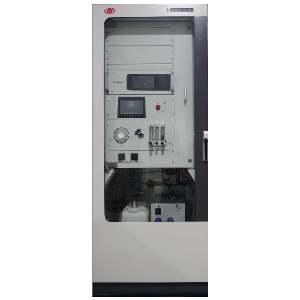
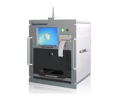
北京欧兰科技发展有限公司为您提供《喷嘴中直径对火焰举升长度的影响检测方案(尾气检测)》,该方案主要用于其他中直径对火焰举升长度的影响检测,参考标准--,《喷嘴中直径对火焰举升长度的影响检测方案(尾气检测)》用到的仪器有汽车发动机多参量测试系统、德国LaVision PIV/PLIF粒子成像测速场仪、PLIF平面激光诱导荧光火焰燃烧检测系统、LaVision SprayMaster 喷雾成像测量系统、激光诱导白炽光烟雾粒子成像分析仪(LII)
推荐专场
汽车尾气分析仪
更多


相关方案
更多
该厂商其他方案
更多